What Is an Electric Transformer? Complete Beginner’s Guide to Power Transformers
2026-07-20
Modern civilization depends heavily on stable and efficient electrical systems. From residential lighting and industrial manufacturing to hospitals, transportation networks, and data centers, nearly every sector relies on the safe transmission and distribution of electrical energy. At the center of this infrastructure is one of the most important inventions in electrical engineering: the electric transformer.
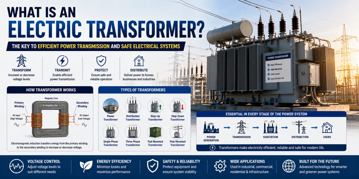
An electric transformer is an electrical device designed to transfer electrical energy between circuits through electromagnetic induction. Its primary function is to increase or decrease voltage levels efficiently, allowing electricity to travel long distances while minimizing energy loss. Without power transformers, modern electrical grids and local distribution systems would not be economically or technically practical.
Today, electrical transformers are used across every stage of the electrical network, including generation stations, electrical substations, industrial facilities, renewable energy systems, and residential neighborhoods. Different transformer designs support different operational requirements, ranging from ultra-high-voltage transmission to low-voltage local power supply.
1. What Is an Electric Transformer?
An electric transformer is a static electrical device that transfers alternating current (AC) electrical energy between two or more circuits using electromagnetic induction.
Unlike motors or generators, transformers contain no moving mechanical parts.
Their main functions include:
- Increasing voltage levels
- Reducing voltage levels
- Isolating electrical circuits
- Stabilizing electrical systems
- Supporting safe power transmission
Why Transformers Are Essential
Electricity generated at power plants must travel over very long distances before reaching consumers.
If power is transmitted at low voltage:
- The current becomes very high
- Energy losses increase significantly
- Conductors become inefficient
Power transformers solve this problem by increasing voltage for transmission and reducing voltage for safe local distribution.
Basic Transformer Components
A standard electrical transformer contains:
- Magnetic core
- Primary winding
- Secondary winding
- Insulation system
- Cooling system
- Transformer tank or enclosure
The interaction between the coils of wire and magnetic flux enables energy transfer.
2. How Does a Transformer Work?
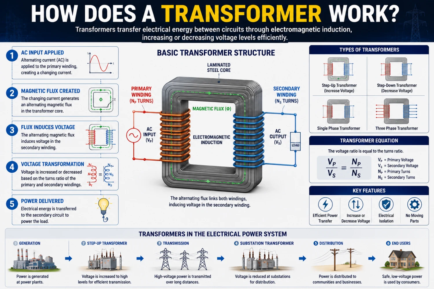
The operating principle of a transformer works is based on:
Electromagnetic induction
This principle was discovered by Michael Faraday in the 19th century.
Primary and Secondary Windings
Every transformer contains:
- Primary winding
- Secondary winding
When alternating current flows through the primary winding, it creates a changing magnetic field inside the transformer core.
This magnetic field induces a voltage in the secondary coil.
Voltage Transformation
The voltage ratio depends on the number of turns in each winding.
If the secondary winding has:
- More turns → voltage increases
- Fewer turns → voltage decreases
This allows transformers to efficiently increase or decrease electrical voltage.
Transformer Equation
The basic transformer relationship is:
Vp / Vs=Np / Ns
Where:
- Vp = Primary voltage
- Vs = Secondary voltage
- Np = Primary turns
- Ns = Secondary turns
This equation forms the foundation of transformer electrical engineering.
3. Main Types of Electrical Transformers
Different applications require different transformer designs.
Main Types of Electrical Transformers and Their Applications
|
Transformer Type |
Main Function |
Typical Voltage Range |
Common Applications |
|
Power Transformer |
High-voltage transmission |
33 kV to 765 kV |
Transmission substations |
|
Distribution Transformer |
Local voltage reduction |
400 V to 33 kV |
Residential and commercial distribution |
|
Step-Up Transformer |
Increase voltage |
Medium to high voltage |
Power generation plants |
|
Step-Down Transformer |
Reduce voltage |
High to low voltage |
Industrial and residential systems |
|
Single-Phase Transformer |
Single-phase power supply |
Low voltage |
Homes and small businesses |
|
Three-Phase Transformer |
Three-phase power distribution |
Medium and high voltage |
Industrial facilities |
|
Pad Mounted Transformer |
Underground distribution |
Medium voltage |
Urban infrastructure |
|
Pole-Mounted Transformer |
Overhead local distribution |
Low to medium voltage |
Rural electrical systems |
Power Transformer
Power transformer systems are used in:
- Transmission networks
- Electrical substations
- High-capacity industrial systems
They operate at high voltages and high efficiency.
Distribution Transformer
Distribution transformers support local distribution networks.
They reduce transmission voltage to usable consumer levels.
These are commonly seen as:
- Electric pole transformer systems
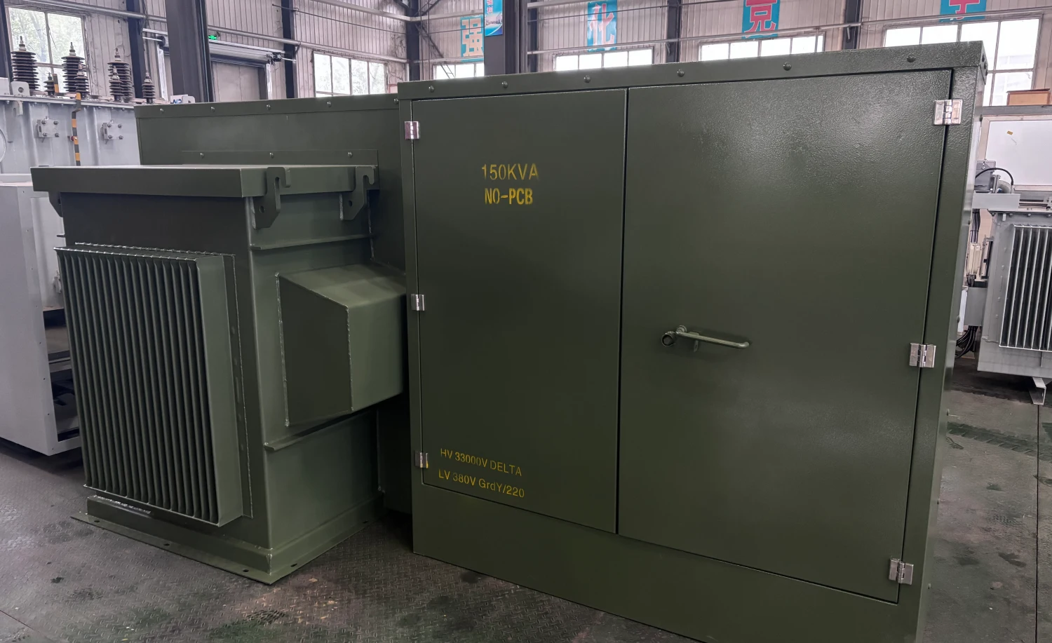
- Pad-mounted transformers
- Ground-mounted transformer units
Step-Up Transformer
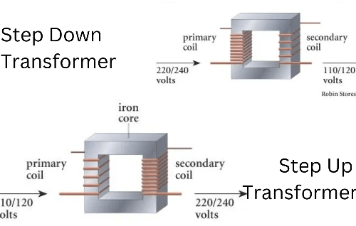
A step-up transformer increases voltage.
Applications include:
- Power generation stations
- Renewable energy plants
- Long-distance transmission systems
Step-Down Transformer
A step-down transformer reduces voltage for:
- Residential buildings
- Commercial facilities
- Industrial equipment
Single-Phase Transformer
Single-phase transformer units are widely used in:
- Residential systems
- Small commercial buildings
- Lighting circuits
4. Transformer Construction and Core Design
Transformer construction directly affects efficiency, reliability, and operational lifespan.
Main Components Inside an Electrical Transformer
|
Transformer Component |
Function |
Common Materials |
|
Transformer Core |
Transfers magnetic flux |
Laminated silicon steel |
|
Primary Winding |
Receives input voltage |
Copper or aluminum |
|
Secondary Winding |
Delivers output voltage |
Copper or aluminum |
|
Insulation System |
Prevents electrical breakdown |
Oil, paper, epoxy resin |
|
Cooling System |
Dissipates heat |
Mineral oil or air cooling |
|
Transformer Tank |
Protects internal components |
Carbon steel |
|
Bushings |
Connect external circuits |
Porcelain or polymer |
|
Tap Changer |
Adjusts voltage ratio |
Mechanical switching system |
Transformer Core
The transformer core is typically made from laminated silicon steel.
Its purpose is to:
- Concentrate the magnetic flux
- Reduce energy loss
- Improve efficiency
Laminated construction reduces eddy current losses.
Coils of Wire
Transformer windings use insulated copper or aluminum conductors.
Copper windings offer:
- Higher conductivity
- Better thermal performance
- Improved durability
Insulation Systems
Transformer insulation prevents electrical breakdown between windings and grounded components.
Common insulation materials include:
- Mineral oil
- Paper insulation
- Epoxy resin
- Pressboard
Insulation quality strongly affects transformer lifespan.
Cooling Systems
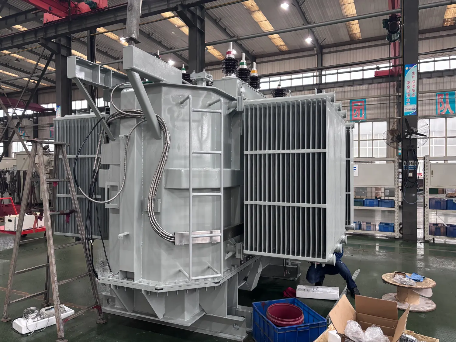
Large electric power transformer systems generate significant heat.
Cooling methods include:
- ONAN (Oil Natural Air Natural)
- ONAF (Oil Natural Air Forced)
- Dry-type air cooling
Effective cooling improves reliability.
Table: Transformer Cooling Methods Comparison
|
Cooling Method |
Description |
Typical Applications |
|
ONAN |
Oil Natural Air Natural |
Standard distribution transformers |
|
ONAF |
Oil Natural Air Forced |
Large power transformers |
|
OFAF |
Oil Forced Air Forced |
High-capacity transmission systems |
|
Dry-Type Air Cooling |
Air-cooled transformer |
Commercial buildings |
|
Water Cooling |
Water-assisted cooling |
Industrial power stations |
5. Power Transformers in Electrical Systems
Modern electrical systems rely heavily on transformer networks.
Electrical Generation
Power stations use step-up transformers to increase voltage immediately after generation.
Higher voltage reduces transmission losses.
Transmission Networks
High voltages allow efficient long-distance power transmission.
Large power transformers in substations may operate at:
- 110 kV
- 220 kV
- 500 kV
- Ultra-high-voltage levels
Typical Transformer Voltage Levels Across Electrical Systems
|
Electrical System Stage |
Typical Voltage Level |
Transformer Function |
|
Power Generation |
11 kV – 25 kV |
Generator output voltage |
|
Step-Up Transmission |
110 kV – 765 kV |
Increase voltage for long-distance transmission |
|
Transmission Substation |
220 kV – 500 kV |
Grid interconnection |
|
Distribution Substation |
11 kV – 33 kV |
Reduce voltage for local distribution |
|
Commercial Distribution |
400 V – 11 kV |
Building and industrial supply |
|
Residential Distribution |
120 V – 240 V |
Home electrical supply |
|
Industrial Systems |
400 V – 35 kV |
Heavy equipment operation |
Electrical Substation Transformer Systems
Electrical substation transformer installations regulate voltage between different grid sections.
Substations also provide:
- Grid protection
- Switching operations
- Voltage regulation
Local Distribution Networks
Electric pole transformer systems reduce voltage for homes and businesses.
Typical residential voltages include:
- 120V
- 230V
- 400V
depending on regional standards.
6. Common Transformer Applications
Transformers are used across almost every industry.
Industrial Manufacturing
Industrial facilities use transformers for:
- Heavy machinery
- Motor control
- Process automation
- Furnace systems
Renewable Energy Systems
Solar and wind farms use power transformers to integrate renewable energy into the grid.
Commercial Buildings
Commercial electrical systems rely on transformers for:
- HVAC systems
- Elevators
- Lighting systems
- Backup power systems
Data Centers
Modern data centers require highly reliable electrical transformer systems to support:
- Servers
- Cooling systems
- UPS infrastructure
Transportation Infrastructure
Railways and metro systems use specialized transformers for traction power systems.
7. Transformer Efficiency and Operational Challenges
Transformer efficiency is one of the most important design considerations.
Transformer Losses
Main transformer losses include:
Copper Losses
Caused by winding resistance.
Core Losses
Caused by:
- Eddy currents
- Magnetic hysteresis
Why Efficiency Matters
Even small efficiency improvements create major energy savings over long operational periods.
Modern high-efficiency power transformers help reduce:
- Grid operating costs
- Carbon emissions
- Energy waste
Common Operational Challenges
Transformers may experience:
- Overheating
- Insulation aging
- Moisture contamination
- Harmonic distortion
- Short-circuit stress
Proper maintenance is essential.
8. Future Trends in Power Transformer Technology
Transformer technology continues evolving rapidly.
Smart Transformers
Modern smart transformers include:
- Real-time monitoring
- Digital diagnostics
- Remote communication systems
Renewable Energy Integration
As renewable energy adoption increases, transformers must support:
- Variable loads
- Bidirectional power flow
- Grid stability
Environmentally Friendly Insulation
New transformer designs increasingly use:
- Biodegradable ester fluids
- Low-emission materials
- Improved fire-resistant insulation
Compact High-Efficiency Designs
Modern electrical transformer box systems are becoming:
- Smaller
- More efficient
- Easier to install
especially in urban electrical infrastructure.
FAQ Questions and Answers
1. What is an electric transformer used for?
An electric transformer is used to increase or decrease voltage levels in electrical systems. It enables efficient power transmission, local distribution, voltage regulation, and safe operation of electrical equipment in residential, commercial, and industrial applications.
2. How does a power transformer work?
A power transformer works through electromagnetic induction. Alternating current flowing through the primary winding creates a magnetic field in the transformer core, which induces voltage in the secondary winding and transfers electrical energy between circuits.
3. What is the difference between a power transformer and a distribution transformer?
Power transformers are mainly used in high-voltage transmission systems and electrical substations, while distribution transformers reduce voltage for local distribution to homes, commercial buildings, and industrial facilities.
4. Why are transformer cooling systems important?
Transformer cooling systems remove heat generated by electrical losses. Proper cooling improves transformer efficiency, extends insulation life, prevents overheating, and increases operational reliability.
5. What are the main types of electrical transformers?
Common transformer types include power transformers, distribution transformers, step-up transformers, step-down transformers, single-phase transformers, three-phase transformers, pad-mounted transformers, and pole-mounted transformers.
Conclusion
The electric transformer remains one of the most essential technologies in modern electrical engineering. By efficiently increasing or decreasing voltage levels, transformers make long-distance power transmission, local distribution, and safe electricity usage possible across residential, commercial, and industrial systems.
From electrical substation transformer installations to electric pole transformer networks and high-capacity power transformers, these devices form the backbone of global electrical infrastructure. Understanding transformer works, winding design, insulation systems, and voltage transformation principles is critical for engineers, contractors, utility companies, and industrial operators.
As global electrical systems continue evolving toward smarter grids, renewable energy integration, and higher efficiency standards, advanced transformer technologies will remain fundamental to the future of reliable and sustainable power distribution.

Related Articles
Related Products
Three Phase Pole Mounted Transformer
The three phase pole mounted transformer delivers balanced, high-capacity power transformation for overhead distribution lines, stepping down medium voltages such as 11kV, 22kV, or 33kV to low voltages like 400V/415V or 480V in Y or Delta configurations. Engineered with a five-legged core/coil assembly and premium grain-oriented silicon steel, it reduces magnetic losses and harmonics while achieving high efficiency levels per DOE and IEC standards. The oil-immersed tank with ONAN cooling ensures effective heat dissipation and a 65°C rise rating for continuous operation under demanding loads. Robust features include porcelain HV bushings, polymer LV bushings, tin-plated terminals for copper/aluminum connections, pressure relief devices, and lightning arrester provisions, offering excellent weather resistance and protection in exposed installations. This design provides cleaner aesthetics, lower installation costs compared to single-phase banks, and reliable service for motor starts and variable loads, making it a top choice for utilities modernizing grids.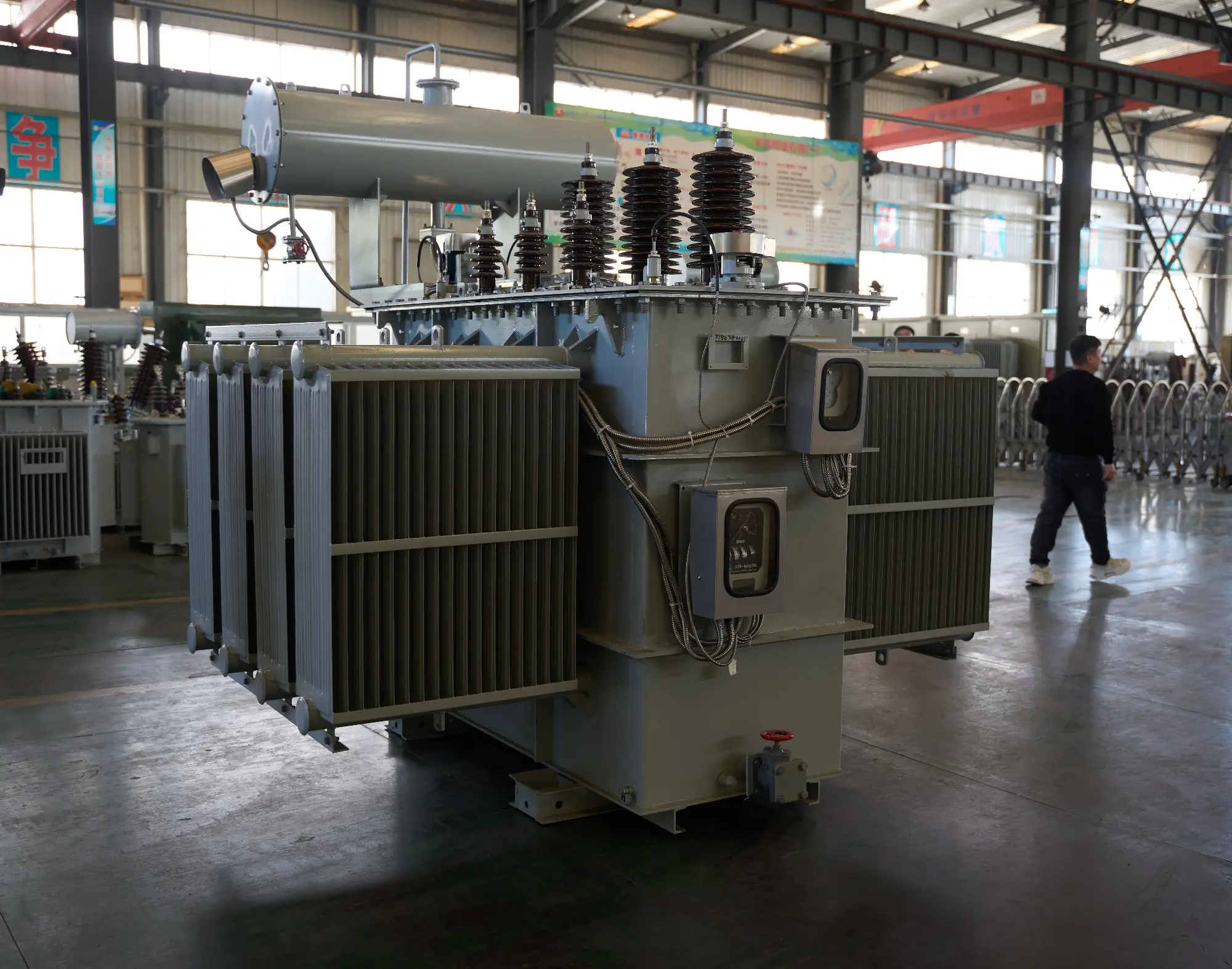
35kV 46kV Power Transformer
NPC ELECTRIC's 35kV and 46kV power(electrical) transformer complies with international standards such as IEC and ANSI, and features high efficiency, low loss, and strong insulation. This product is widely used in power grid main transformers, power plants, industrial and mining enterprises, and large infrastructure projects. Key features include mineral oil or FR3 natural ester insulation (ONAN/ONAF/ODAF cooling options), copper or aluminum windings, primary voltages 35kV or 46kV (grounded wye or delta, with dual-voltage configurations), secondary voltages 6.6kV, 11kV, 13.8kV, 33kV, or custom (e.g., 13.8kV/480V or 35kV/11kV), BIL ratings 200–650kV depending on voltage class, impedance typically 8–12%, ±2×2.5% or ±5% off-load tap changer (OLTC optional), conservator tank or sealed tank design, Buchholz relay, pressure relief device, oil temperature gauges, winding temperature indicators, and ANSI 61 gray or custom tank finish.
ALLIANCE AAAC Conductor Cable
ALLIANCE AAAC (All Aluminum Alloy Conductor) cables are manufactured in strict compliance with international standards such as ASTM B399, IEC 61089, and BS EN 50182, making them a high-performance and reliable overhead power transmission and distribution solution. Meeting ASTM B398, B399, IEC 61089, and BS EN 50182 standards, this cable handles ampacity up to 350A at 75°C and voltages up to 33kV. The all-alloy construction avoids bimetallic corrosion, providing better resistance in harsh conditions than ACSR. Reduced weight minimizes sag and installation expenses, supporting longer spans. The Alliance AAAC Conductor Cable delivers low electrical losses, high mechanical endurance, and excellent weather tolerance. Flame-retardant variants available. Perfect for urban grids, renewable projects, and coastal setups, it provides cost-effective, low-maintenance power delivery in overhead applications globally, excelling in reliability and lifespan over conventional conductors.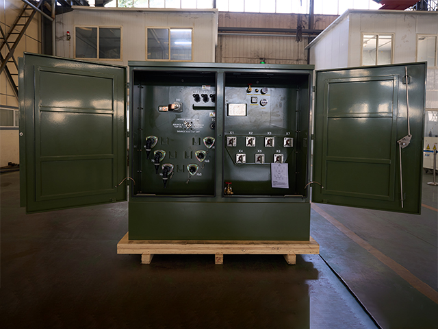
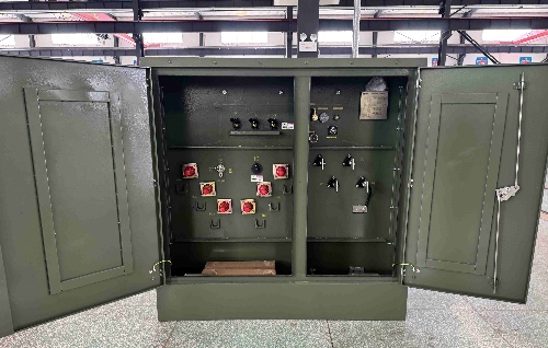
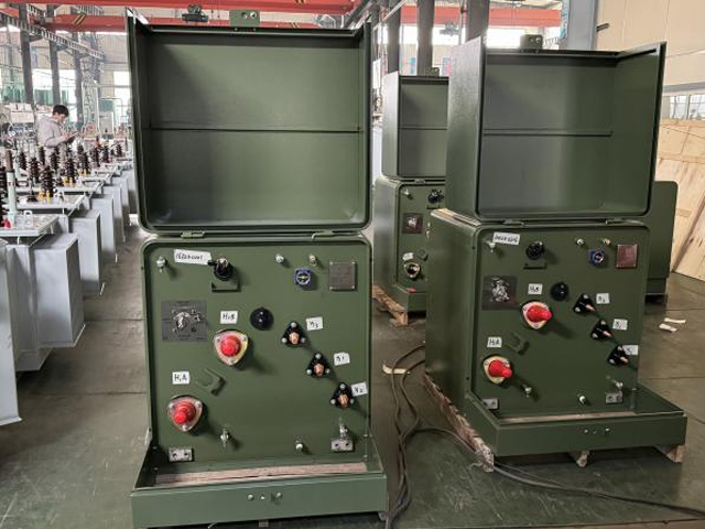
1250kVA Three Phase Pad Mounted Transformer
NPC ELECTRIC's 1250kVA Three Phase Pad Mounted Transformer is a high-performance, oil-immersed distribution transformer engineered for reliable underground power distribution in demanding environments. It delivers exceptional efficiency (up to 99.2% or higher), low no-load and load losses, and a 65°C average winding rise for extended service life exceeding 30-40 years. Key components include high-grade silicon steel core, aluminum or copper windings, 5-position tap changer (±2x2.5%), pressure relief valve, oil level gauge, and tamper-resistant enclosure in Munsell green finish.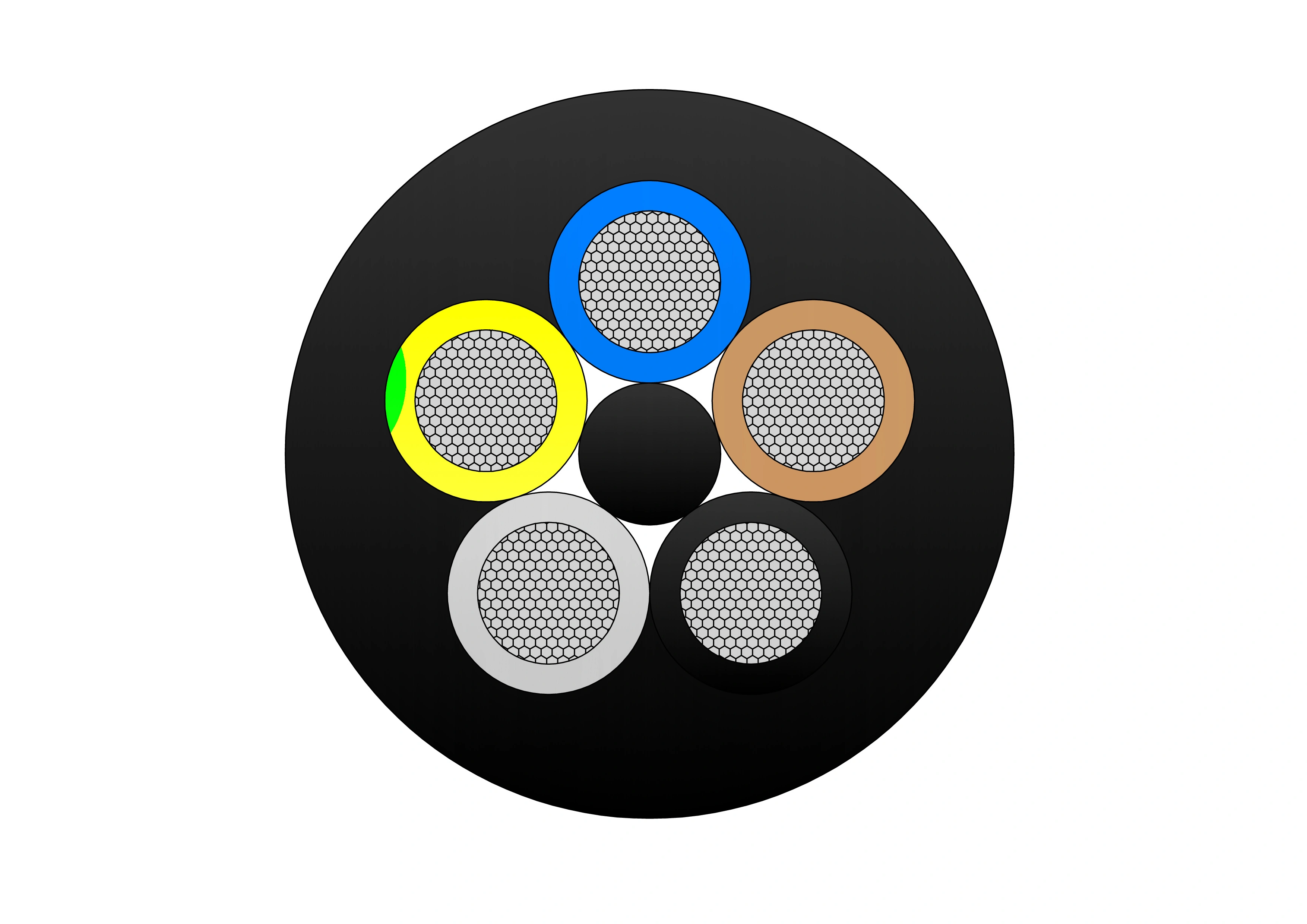
Variable Frequency Drive (VFD) EMC 2YSL(st)CY Cable
The Variable Frequency Drive (VFD) EMC 2YSL(st)CY Cable is a flexible, low-voltage power and control cable designed for use with frequency-controlled drives. Built to DIN VDE 0250 standards, it features low capacitance, enhanced EMC shielding with aluminium-foil and tinned copper braid, and PVC outer sheath for durability. It provides excellent electromagnetic compatibility, oil and grease resistance, and reliable performance under medium mechanical stress. Ideal for connecting motors to inverters, this cable supports fixed and temporary installations in both indoor and outdoor environments (excluding direct burial).
60kV Dyn11/Yyn0 Pure Copper Oil-Immersed Power Transformer
The 60kV Dyn11/Yyn0 Pure Copper Oil-Immersed Power Transformer is designed for regional 35–50 kV distribution networks and industrial substations. It adopts 99.99 % electrolytic pure copper windings, Class A insulation, corrugated tank + ONAN natural cooling, and energy-saving S11/S13 core with up to 40 % lower no-load loss. Standard vector groups Dyn11 or Yyn0, off-circuit tap changer ±5 % or ±2×2.5 % (on-load optional). Fully compliant with IEC 60076, lightning impulse 250 kV peak, PD <10 pC. Fully sealed or conservator design prevents oil aging and moisture ingress. Low noise ≤58 dB, strong short-circuit withstand, suitable for high-altitude and harsh environments. Vacuum oil filling + nitrogen sealing ensures>30-year lifespan. Widely used in mining, petrochemical, renewable energy, and urban 50 kV networks.
40MVA 110kV Three Phase Oil Immersed Transformer for Substation
The 40MVA 110kV Three Phase Oil Immersed Transformer is engineered for reliable high-voltage transmission and distribution in substations and power plants. Featuring high-purity copper windings, advanced ONAN/ONAF cooling, and on-load tap changer (OLTC ±8×1.25%), it delivers superior efficiency and minimal no-load/loss performance (SZ11/SZ13 series). Fully compliant with IEC 60076, GB 6451, and IEEE standards, it withstands 200kV lightning impulse and offers partial discharge below 10pC. The corrugated tank design ensures optimal heat dissipation and mechanical strength in harsh environments. Ideal for 110/33kV, 110/11kV, or 110/6.3kV step-down applications. Vacuum oil filling and nitrogen sealing guarantee long-term insulation integrity. Trusted by utilities worldwide for stable, maintenance-free operation over 30+ years. Contact us for technical datasheet and competitive pricing.
1/0 Bull Aluminum Conductor Duplex Overhead Service Drop Cable
1/0 Bull Aluminum Conductor Duplex Overhead Service Drop Cable is designed for reliable secondary overhead power distribution from utility lines to residential and commercial service entrances. The cable consists of two aluminum conductors, typically one phase conductor and one neutral messenger, stranded concentrically to provide flexibility, strength, and stable electrical performance. The 1/0 Bull size offers a balanced combination of current-carrying capacity and mechanical durability, making it suitable for short- to medium-span service drop installations. Aluminum conductors ensure lightweight handling, reduced installation effort, and excellent corrosion resistance in outdoor environments. Manufactured in accordance with relevant ASTM and utility standards, the 1/0 Bull Aluminum Conductor Duplex Overhead Service Drop Cable delivers consistent conductivity, controlled sag, and dependable long-term operation. It is widely used by utilities and contractors seeking a cost-effective, easy-to-install solution for overhead service connections.
Triplex URD Cable
The Triplex URD Cable is a cost-effective and reliable 600V underground residential distribution cable engineered for service entrance and secondary power delivery. It consists of three insulated AA8000 aluminum alloy phase conductors and a concentric neutral, all encased in a durable black polyethylene sheath. The triplex design offers a compact footprint, excellent flexibility, and easy handling during direct burial installation. With XLPE insulation, this cable provides superior electrical performance and moisture resistance. Lightweight and corrosion-resistant, the Triplex URD Cable is an economical alternative to copper while maintaining high conductivity and mechanical strength. Manufactured to UL 854 and ICEA standards, it undergoes extensive quality testing to ensure consistent performance and long service life in underground environments.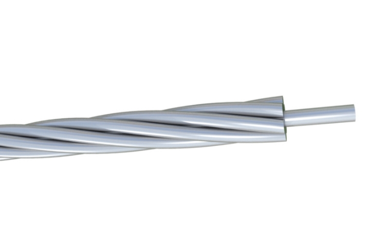
High Quality 16 Gauge Galvanized Steel Conductor Wire Supplier
The 16 Gauge Galvanized Steel Conductor Wire is a versatile and durable solution for electrical and construction applications. Made from premium steel and coated with a high-quality zinc layer through hot-dip galvanization, it provides superior resistance to corrosion and environmental wear. This wire is engineered to deliver consistent tensile strength while maintaining flexibility, making it suitable for grounding systems, fencing, and binding applications. The 16-gauge size ensures easy handling and adaptability for various installation requirements. Its uniform zinc coating enhances longevity and reduces maintenance costs, especially in outdoor environments exposed to moisture and chemicals. Manufactured under strict quality control systems, the wire meets international standards for performance and reliability. With customizable specifications such as coating thickness and tensile strength, the 16 Gauge Galvanized Steel Conductor Wire is widely trusted by contractors and industrial users for its durability and cost-effectiveness.
Type 241 Flexible Rubber Screened Mining Cable
The Type 241 Flexible Rubber Screened Mining Cable is a medium-voltage, rubber-insulated cable engineered for underground coal mining and general mining applications. It features tinned annealed copper conductors, EPR insulation, and a semi-conductive thermosetting screen for excellent electrical performance. The cable’s three screened power cores and three earth cores are arranged with a central pilot core for enhanced safety and control. With an HD-85-PCP extra heavy-duty outer sheath, it delivers oil resistance, flame retardancy, and superior mechanical durability. Compliant with AS/NZS 1802 and related standards, it ensures reliable operation under harsh mining conditions. The Type 241 is specifically suited for high-power trailing applications in coal and metalliferous mines, powering longwall shearers, continuous miners, shuttle cars, loaders, and face equipment with maximum safety and uptime.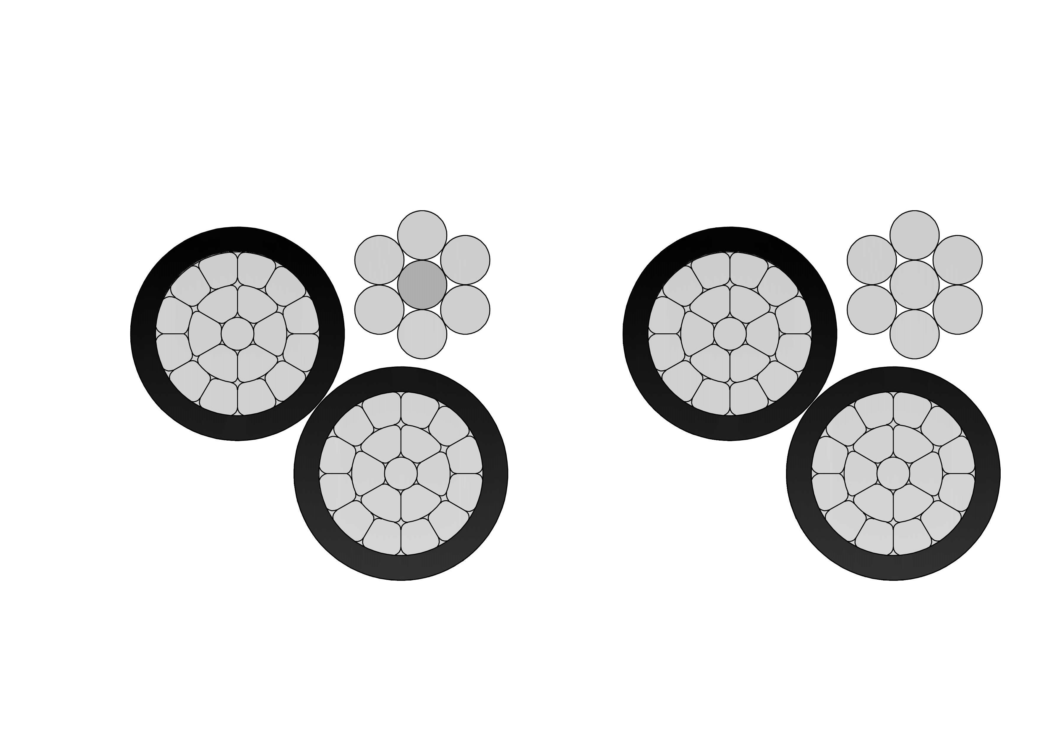
2 Clam Aluminum Conductor Triplex Overhead Service Drop Cable
2-2-2 Clam Aluminum Conductor Triplex Overhead Service Drop Cable provides high-performance overhead power transmission for utility-to-consumer connections. Constructed with compressed or concentric 1350-H19 aluminum phase conductors (#2 AWG), durable black XLPE insulation for enhanced thermal and environmental protection, and a bare neutral messenger (#2 AWG ACSR or AAC), it delivers efficient conductivity, corrosion resistance, and structural support. Suitable for 600V phase-to-phase applications with conductor temperatures up to 90°C, offering ≈150A ampacity. Meets or exceeds ASTM B-230/B-231/B-232/B-399 and ICEA S-76-474 requirements. Its lightweight design and flexibility make installation efficient, while rugged construction ensures long service life in demanding outdoor exposure to weather, abrasion, and mechanical stress.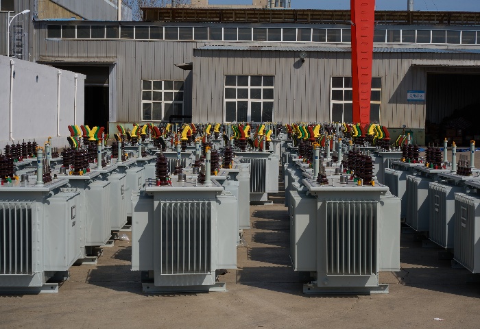
33kV Oil Immersed Transformer
33kV Oil Immersed Transformer is a high-voltage, three-phase power distribution and step-down unit engineered for reliable operation in 50/60Hz AC transmission and distribution networks with primary voltages up to 33kV (or 30-38.5kV range). It features a hermetically sealed or conservator-type tank with corrugated radiators or detachable coolers for superior thermal management and oil expansion compensation, providing excellent moisture barrier, oxidation resistance, and service life exceeding 35 years. Utilizing premium cold-rolled grain-oriented silicon steel cores with optimized step-lap joints and low-loss designs (S11/S13 series equivalents), it achieves substantial reductions in no-load losses (often 20-40% below older models), paired with high-conductivity copper windings.
NS75/NS90 Duplex Unjacketed Overhead Neutral Supported Cable
Our NS75/NS90 Duplex Unjacketed Overhead Neutral Supported Cable provides economical self-supporting overhead distribution. Consisting of an XLPE-insulated aluminum phase conductor (75 mm² or 95 mm²) supported by a bare ACSR or AAAC neutral messenger without an overall jacket, it meets AS/NZS 3560 and utility requirements. The design reduces material costs while delivering high tracking resistance and mechanical strength for spans up to 100m. Excellent UV and moisture performance ensures longevity in exposed conditions. The NS75/NS90 Duplex Unjacketed Overhead Neutral Supported Cable offers low installation effort, minimal sag, and reliable power delivery for 600/1000V networks. Widely favored in Australia and New Zealand for residential, commercial, and rural service drops requiring lightweight, neutral-supported overhead cables with proven compliance and durability in diverse climates.
115kV 35MVA Three-Phase Oil-Immersed Power Transformer
The 115kV 35MVA Three-Phase Oil-Immersed Power Transformer is designed for reliable and efficient operation in high-voltage transmission and substation applications. Built with high-permeability silicon steel cores and precision-wound copper conductors, it delivers low losses, strong short-circuit withstand capability, and excellent thermal stability. The oil-immersed cooling system ensures effective heat dissipation, enabling continuous operation under heavy-load conditions. A robust tank structure, advanced insulation system, and outdoor-rated protection make the transformer suitable for harsh environmental conditions. Manufactured in accordance with IEC, IEEE, and ANSI standards, this transformer is widely used in utility substations, industrial power systems, and regional transmission networks where long service life, stable voltage regulation, and high operational reliability are critical.Welcome your inquiry
Honesty, Integrity, Frugality, Activeness and Passion