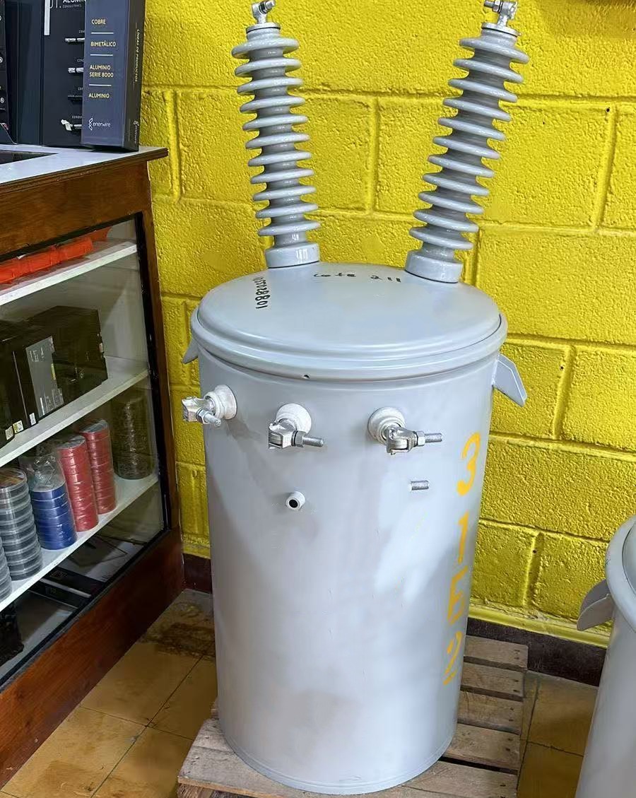


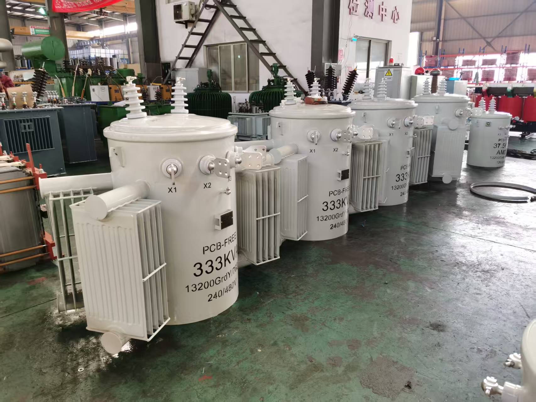
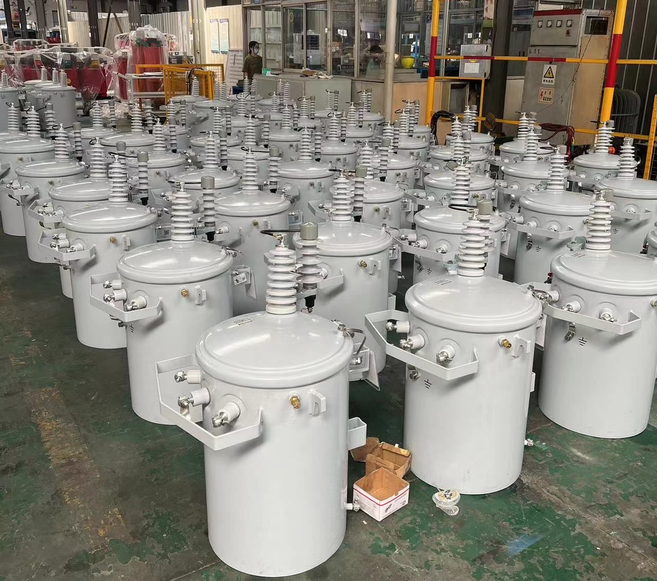
Three Phase Pole Mounted Transformer
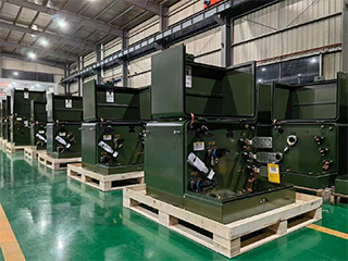
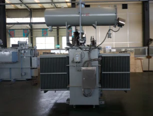
The three phase pole mounted transformer delivers balanced, high-capacity power transformation for overhead distribution lines, stepping down medium voltages such as 11kV, 22kV, or 33kV to low voltages like 400V/415V or 480V in Y or Delta configurations. Engineered with a five-legged core/coil assembly and premium grain-oriented silicon steel, it reduces magnetic losses and harmonics while achieving high efficiency levels per DOE and IEC standards. The oil-immersed tank with ONAN cooling ensures effective heat dissipation and a 65°C rise rating for continuous operation under demanding loads. Robust features include porcelain HV bushings, polymer LV bushings, tin-plated terminals for copper/aluminum connections, pressure relief devices, and lightning arrester provisions, offering excellent weather resistance and protection in exposed installations. This design provides cleaner aesthetics, lower installation costs compared to single-phase banks, and reliable service for motor starts and variable loads, making it a top choice for utilities modernizing grids.
- Primary Voltage Ratings 11kV, 22kV, 33kV(34.5kV, 20kV, 24.9kV)
- Secondary Voltage Ratings 400V, 415V, 380V/220V, 480V
- H.V. Tap Range ± 2×2.5% HV taps or others
- Type Conventional Type
- BIL 30-150kV
- Standards IEEE, ANSI, NEMA, ASTM
- Application workshops, street lighting, and community facilities
- Power Rating 30kVA, 50kVA, 75kVA, 100kVA, 150kVA, 200kVA, 250kVA, 315kVA, 400kVA, 500kVA
- Certificate CE, ISO
- Cooling Method ONAN, KNAN
- Oil Mineral Oil or FR3
- Opeartion Step Down
Technical Specifications
Customization Optional
Packing and Shipping
Manufacturer Test
Routine Testing
Application
Technical Specifications
Three Phase Pole Mounted Transformer
Technical Specifications
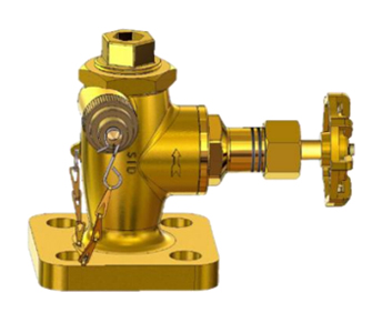
Accessories
| Rated Power | 30kVA, 50kVA, 75kVA, 100kVA, 150kVA, 200kVA, 250kVA, 315kVA, 400kVA, 500kVA |
| Rating Primary Voltage | 12.4-34.5kV |
| Secondary Voltage | 480-240V 240-120V 277V Customized |
| Frequency | 50/60Hz |
| Vector Group | Ii0,Ii6 |
| Winding Material | Aluminum/Copper |
| Efficiency | As IEEE,Doe 2016,CAS Std or Customized |
| Impedance Voltage | Nominal 2% or Customized 1.1-5.75% |
| Altitude | ≤1,000m or Customized |
| Color | ANSI 70 Light gray/Munsell 7GY3.29/1.5 or customized etc |
| Tank material | Mild Steel, 304 Stainless Steel |
| Lifting Lug |
| Tap Changer |
| Pressure Relief Valve |
| Tank Cover and clamp |
| L.V Bushing |
| HV Bushing |
| Ground Strap |
| Nameplate |
| Non-PCB decal |
| High Voltage Warning Signs |
| Suport lug |
| Oil fill valve |
Customization Optional
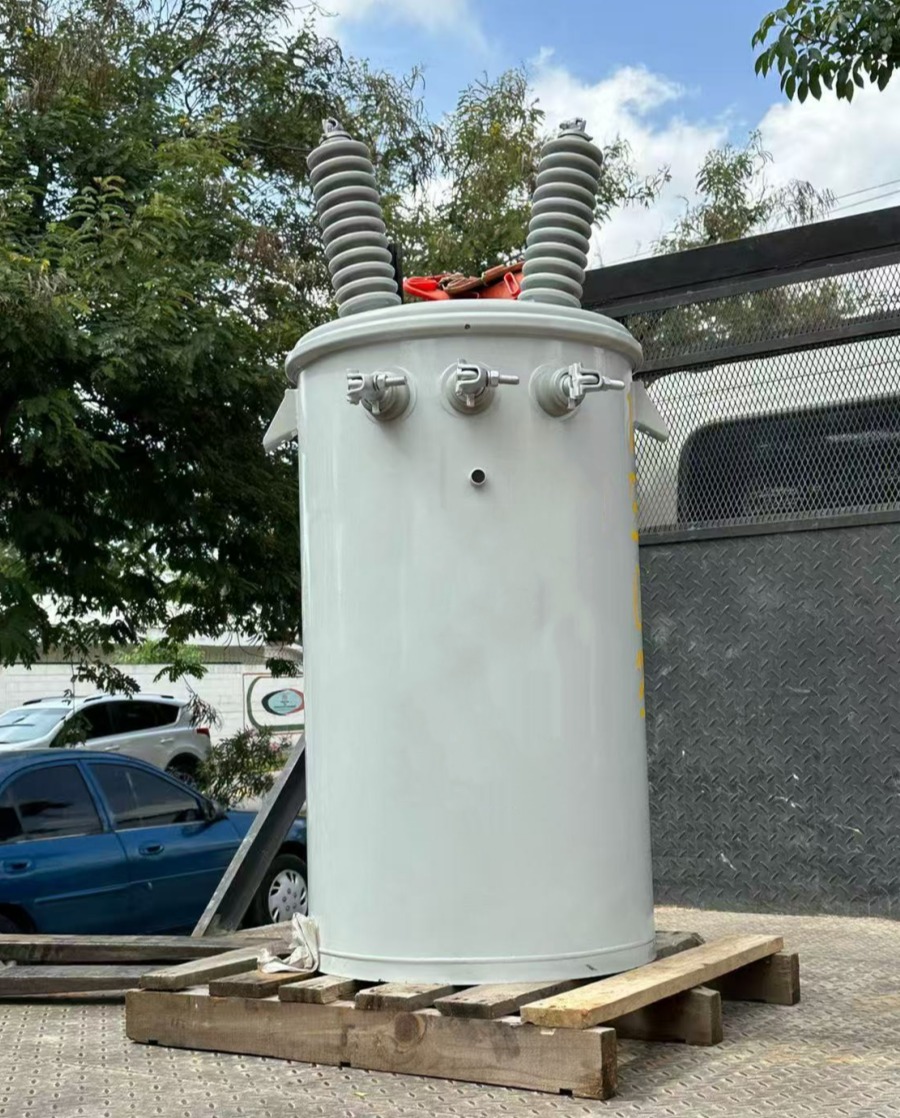
Three Phase Pole Mounted Transformer
Tailor the three phase pole mounted transformer to precise application needs with extensive configuration flexibility that optimizes performance across diverse overhead systems. Select primary voltages from 6.6kV to 34.5kV, including common 11kV, 22kV, or 33kV ratings, paired with secondary outputs such as 208Y/120V, 400Y/230V, 415V, 480Y/277V, or custom mid-tap arrangements for regional compatibility. Winding materials offer aluminum for cost-effective lightweight construction or copper for enhanced conductivity and reduced hotspots in high-demand scenarios. Tank styles include rectangular for compact pole space and stability or round for traditional setups, with five-legged or triplex core/coil options to suit motor-heavy loads. Cooling remains ONAN standard but can upgrade to fan-assisted for extreme conditions, while tap changers provide ±5% or wider off-circuit adjustments. Impedance ranges from 4.5% to 6% balance fault currents, and protective enhancements like internal fuses, expulsion links, wildlife guards, or arrester brackets improve safety. For sustainability, natural ester fluids offer higher fire safety and biodegradability over mineral oil. These adaptations maximize energy savings, fault tolerance, and ease of pole mounting, delivering a tailored solution that aligns with utility budgets and operational priorities in varied environments.
Additional refinements encompass enclosure coatings for corrosion resistance in coastal or industrial areas, reinforced mounting brackets for seismic zones, or integrated monitoring with thermometers, oil gauges, and load sensors for condition-based maintenance. Bushing options support elevated BIL levels up to 200kV, and capacity scaling from 30kVA to 500kVA accommodates growth. Core optimizations further lower no-load losses, while sound-dampening features minimize acoustic impact in sensitive locations. Whether replacing single-phase banks or expanding three-phase services, these custom features position the three phase pole mounted transformer as a dependable, future-oriented component, ensuring seamless integration, reduced lifecycle costs, and enhanced grid reliability in overhead distribution networks.

Packing and Shipping
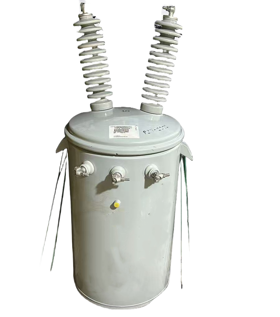
Three Phase Pole Mounted Transformer
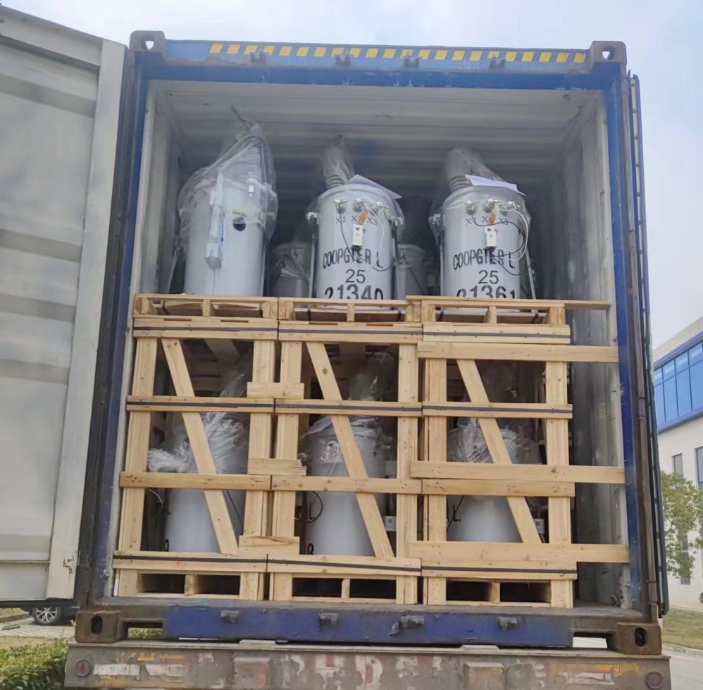
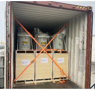
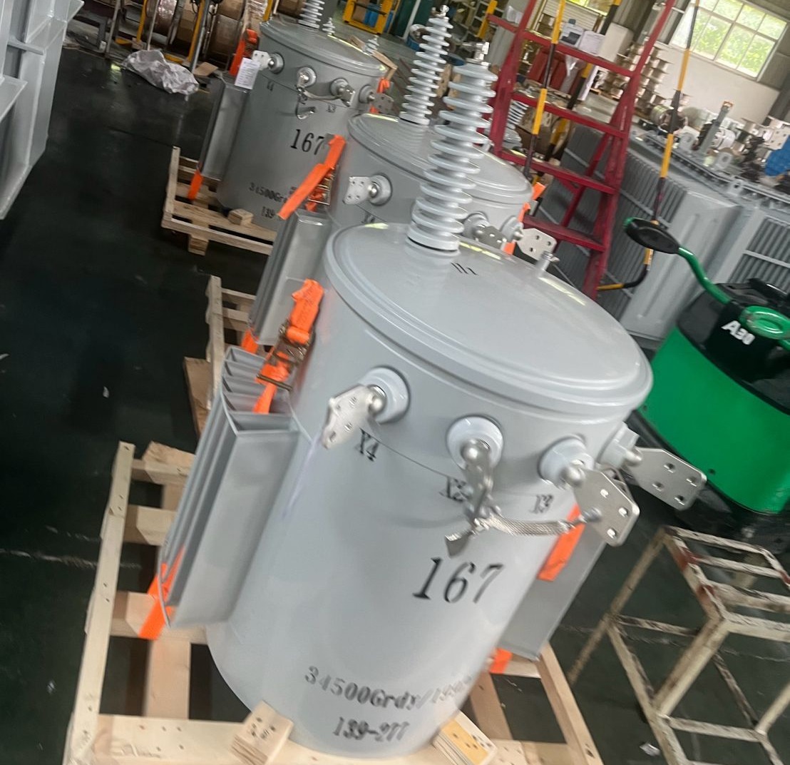
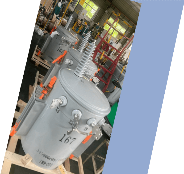
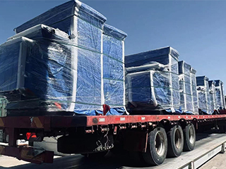
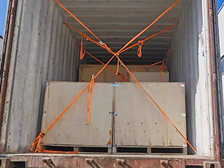
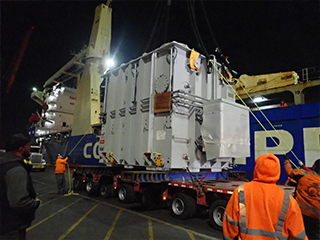
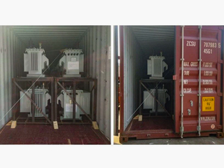
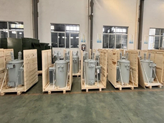
Packaging for the three phase pole mounted transformer employs robust export-grade wooden crates with reinforced steel strapping and internal timber supports to handle substantial weight and prevent movement during transit. High-density foam inserts, corner protectors, and vibration-dampening pads shield bushings, terminals, and the tank from shocks, while vacuum sealing combined with desiccant packs and nitrogen blanketing safeguards oil quality against moisture and oxidation. HV and LV bushings receive individual protective covers, ports are securely capped, and partial oil drainage ensures transport safety. Comprehensive labeling includes weight distribution, lifting points, handling warnings, and international compliance symbols, providing maximum protection from factory to installation site.
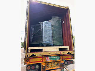
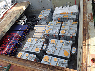
Shipping strategies accommodate the transformer's size and weight, utilizing specialized flatbed trailers with hydraulic suspensions and heavy-duty securement for domestic overland routes, protected by full tarpaulin enclosures against environmental exposure. International transport uses open-top or flat-rack containers on ocean vessels, with IMO-standard lashing, corrosion preventives, and bracing for secure sea passage. GPS satellite tracking delivers real-time visibility, supported by all-risk insurance coverage throughout the journey. Strict adherence to IEEE, IEC, and customs regulations facilitates smooth border processing, reducing delays for efficient global delivery of the three phase pole mounted transformer.
Sustainability principles guide packing decisions, prioritizing recyclable FSC-certified wood and minimized single-use materials while maximizing load efficiency to lower emissions. Impact and tilt recorders attached to crates record transit conditions, enabling post-arrival verification and swift claim handling if necessary. Accessories such as arresters, gauges, or mounting hardware ship in separate labeled crates with detailed inventories for easy reconciliation. Partner carriers experienced in oversized electrical cargo obtain required permits and follow rigorous safety protocols across road, rail, and maritime segments.
Upon delivery, comprehensive support includes route assessments for pole access challenges, step-by-step unpacking instructions, oil refilling procedures, and torque specifications for connections. Collaboration with installation teams ensures safe handling and rapid commissioning. This holistic logistics framework preserves transformer integrity, accelerates deployment, and supports uninterrupted power reliability in three-phase overhead distribution projects worldwide.
32
32 years of industry experience
Manufacturer Test
Three Phase Pole Mounted Transformer
Progress Test
During initial fabrication stages of the three phase pole mounted transformer, progress tests concentrate on core assembly validation, inspecting five-legged grain-oriented silicon steel laminations for precise stacking, burr elimination, and insulation integrity using epstein frame measurements to achieve targeted low no-load losses. Winding verification assesses conductor layering uniformity and inter-turn insulation strength via stepped hipot testing to uncover early defects. Preliminary DC resistance checks on all three phases use four-wire techniques at ambient temperature, ensuring values align with specifications within 0.5%. Turns ratio testing across taps employs precision bridges for deviations below 0.2%. Core clamping pressure is confirmed to avoid buckling, and vibration trials simulate transport effects. Oil sampling verifies dielectric strength exceeding 35kV and controlled moisture/acidity levels. Tank weld examinations apply ultrasonic and dye penetrant methods for seam reliability, while mounting provisions undergo load-bearing tests. Digital logging of all data enables quality trend analysis and timely adjustments.
Design Tests
All transformers will be tested after finishing the production, test items as follows:
♦ Insulation Power Factor
♦ Ratio, Polarity, and Phase Relation
♦ Winding Resistance
♦ Impulse Tests
♦ On load Loss Test
♦ No Load Loss Test
♦ Leak Test
♦ DC Insulation Resistance Test
♦ Transformer Turns Ratio/TTR (All Tap Voltages)
♦ Impedance Voltage & Load Loss (Rated Voltage)
♦ Induced Voltage
♦ Lightning Impulse
♦ Insulation Resistance (Rated Voltage)
♦ Temperature Rise
♦ Dielectric Withstand (Hipot)
Transformer Factory Acceptance Test
Factory acceptance testing for the three phase pole mounted transformer commences with exhaustive visual and dimensional inspections against engineering drawings, evaluating tank construction, bushing alignment, terminal plating, and enclosure integrity. Winding DC resistance measurements apply Kelvin bridge methods with temperature correction, holding results within 0.8% of design targets. Turns ratio and vector group validation across all taps uses high-accuracy TTR equipment for errors under 0.3%. Power factor and capacitance testing at 10kV limits dissipation factor below 0.45%, confirming sound insulation. No-load loss and exciting current determination at rated voltage verifies efficiency compliance, restricting excitation to 1.8% maximum. Load loss and impedance quantification through short-circuit application yields precise efficiency figures exceeding 98%. Power frequency withstand testing applies appropriate kV levels for one minute without breakdown. Induced voltage test at increased frequency stresses inter-turn insulation. Oil quality assessment includes breakdown voltage over 40kV and low dissolved gas content.
Routine Test - Transformer Turns Ratio/TTR
Purpose of Testing
The purpose of the transformer turns ratio (TTR) test is to confirm whether the voltage ratio between each tap of the transformer meets the design requirements and ensure that the transformer winding is connected correctly. By measuring the voltage ratio of each tap, it is possible to detect whether there is a fault or deviation in the transformer winding.
Testing Equipment
TTR tester: such as Doble, Megger, Omicron and other brands of transformer winding ratio tester.
Voltage source: usually AC 10 V to 30 V , used to test different voltages for each tap.
Temperature and humidity meter: used to record environmental conditions during the test to ensure test accuracy.
Current probe: used to measure the load current of the winding and ensure the accuracy of the test results.
Pre-Test Preparation
Disconnect all transformer tap-changers from the power supply and ensure that all equipment is properly grounded and discharged.
Perform the test under suitable environmental conditions: relative humidity below 75% and no rain (recommended temperature: 20-30°C). Avoid high humidity or bad weather that may affect the test accuracy.
Perform the test under suitable environmental conditions: relative humidity below 75% and no rain (recommended temperature: 20-30°C). Avoid high humidity or bad weather that may affect the test accuracy.
Test Progress
Perform the test under suitable environmental conditions: relative humidity below 75% and no rain (recommended temperature: 20-30°C). Avoid high humidity or bad weather that may affect the test accuracy.
Measure and Record
Start the test and record the following parameters:
The voltage ratio between the windings
Deviation of the measured value from the rated ratio
The voltage ratio between the windings
Deviation of the measured value from the rated ratio
Temperature Correction
If necessary, perform temperature correction on the measured turns ratio data (especially when testing at higher or lower temperatures). Generally, the standard reference temperature for temperature correction is 20°C.
Repeat Testing (if necessary)
If necessary, perform temperature correction on the measured turns ratio data (especially when testing at higher or lower temperatures). Generally, the standard reference temperature for temperature correction is 20°C.
Evaluation Criteria (Reference)
Turns ratio error ≤ 0.5% (pass)
0.5% < Turns ratio error ≤ 1% (caution)
Turns ratio error > 1% (further inspection or corrective action required)
0.5% < Turns ratio error ≤ 1% (caution)
Turns ratio error > 1% (further inspection or corrective action required)
*These comprehensive tests ensure that each transformer meets performance standards and operates
reliably under various conditions.
Application
The three phase pole mounted transformer performs optimally in rural electrification projects combined with agricultural and small industrial operations, providing balanced power to farms, processing plants, irrigation systems, and village clusters while supporting motor-driven equipment and occasional renewable tie-ins.


Technical Advantages
● 30+ years of manufacturing experience
● ISO and UL certified production
● Customized cable and transformer solutions


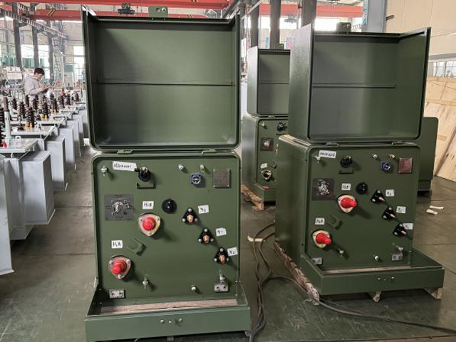
Product Packaging
Transformers Packaging (1)
Transformers Packaging (2)
Transformers Packaging (3)
Transformers Packaging (4)
Transformers Packaging (5)
Transformers Packaging (6)
Transformers Packaging (7)
Transformers Packaging (8)
Related Products
630kVA Three-Phase Oil-Immersed Outdoor Substation Transformer | 220V to 380V Step-Up Transformer
This 630kVA three-phase oil-immersed transformer is designed for outdoor substations, providing reliable voltage conversion from 220V to 380V. With a robust oil-immersed cooling system, it ensures excellent heat dissipation, stable performance, and long service life. Ideal for industrial facilities, commercial power distribution, and utility applications, this step-up transformer delivers consistent efficiency even under heavy load conditions.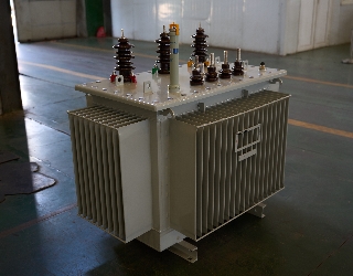
125kVA Oil Immersed Transformer
125kVA Oil Immersed Transformer has the characteristics of high efficiency and low loss, which can reduce power consumption and operation cost, and has significant social benefits. The NPC ELECTRIC 125kva Oil Immersed Transformer, manufactured and supplied by a leading Chinese manufacturer, is are highly advanced electrical device engineered to meet the rigorous demands of modern power distribution systems. These transformers are renowned for their exceptional durability, efficiency, and reliability. As a trusted supplier in China, the manufacturer offers a comprehensive range of 125kVA Oil Immersed Transformers tailored to suit various applications, ensuring optimal performance and long-term value to customers worldwide.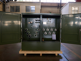
3750kVA Three Phase Pad Mounted Transformer
NPC ELECTRIC's 3750kVA Three Phase Pad Mounted Transformer is a heavy-duty, oil-immersed compartmental-type distribution transformer engineered for high-capacity underground power distribution in large-scale utility and industrial settings. This high-power pad-mounted transformer reduces energy consumption, lowers total ownership costs through superior efficiency and longevity (30+ years), and supports demanding loads with features like vacuum fault interrupters and harmonic mitigation, ideal for reliable, secure power in expansive commercial-industrial networks.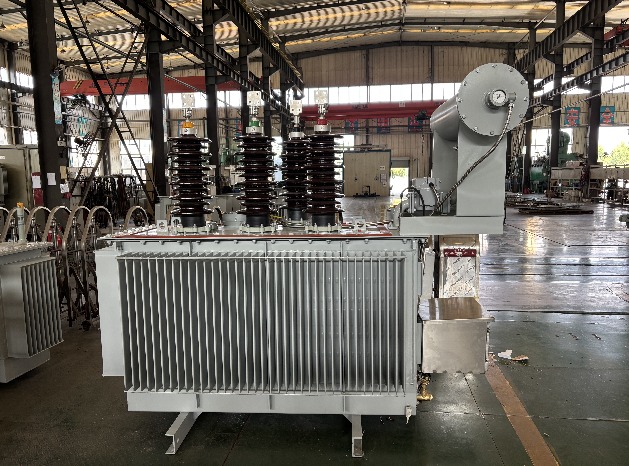
33kV 600A Neutral Zig-zag Grounding Reactor Transformer
The 33kV 600A Neutral Zig-zag Grounding Reactor Transformer is a high-performance grounding solution designed to meet the strict requirements of IEC 60076-1, IEC 60076-5, IEC 60076-20, and GB/T 1094.6 standards, with oil quality tested according to ASTM D6871. This grounding transformer is engineered to provide effective neutral grounding, enhanced system stability, and fault current limitation in medium- and high-voltage networks. With a primary voltage of 33kV and 11432.0kVA rating, the transformer supports 100A power rating for 10 seconds, making it ideal for system grounding applications in substations, industrial facilities, and renewable energy projects. The ONAN cooling method provides efficient heat dissipation for continuous operation, while the use of high-grade mineral insulating oil ensures long-term performance and compliance with international safety standards.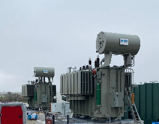
High Voltage 160kV Step-Up Power Transformer: Efficient 20MVA / 30MVA / 60MVA Solutions for Substations
The 160kV High Voltage Step-Up Power Transformer is designed to increase voltage levels efficiently for power generation plants and substation applications. Available in 20MVA, 30MVA, and 60MVA ratings, it supports stable energy transmission from generation sources to high-voltage networks. The transformer adopts a carefully optimized electromagnetic design that enhances voltage conversion efficiency while maintaining controlled thermal and electrical performance. Its oil-immersed insulation system ensures reliable cooling and long-term insulation stability under continuous operating conditions. The structural design emphasizes mechanical strength and operational safety, enabling dependable performance in outdoor substations and demanding grid environments. This step-up transformer is well suited for modern power systems that require efficient voltage elevation, reduced transmission losses, and consistent operational reliability.
161kV 50MVA Two-Winding Power Transformer – Efficient Oil-Filled Design with OLTC
The 161kV 50MVA Two-Winding Power Transformer is engineered to deliver precise voltage control and stable power transfer in high-voltage transmission and substation networks. Featuring an oil-filled insulation system combined with an On-Load Tap Changer (OLTC), this transformer allows continuous voltage adjustment under load conditions without interrupting system operation. The electromagnetic design emphasizes low losses, high operational efficiency, and consistent performance across variable load profiles. Robust mechanical construction enhances resistance to thermal expansion and short-circuit forces, ensuring long-term reliability in demanding grid environments. Optimized oil circulation supports effective heat dissipation, contributing to extended service life and reduced maintenance requirements. This transformer is well suited for modern power systems where voltage stability, operational flexibility, and dependable energy transmission are critical.FAQ From Customers
-
What is a Transformer?A transformer is an electrical device used to change the voltage of alternating current (AC). It works on the principle of electromagnetic induction, converting high-voltage current into low-voltage current or low-voltage current into high-voltage current. Transformers are widely used in power transmission, distribution systems, and various electronic devices.
-
What are the main uses of a transformer?The main use of a transformer is voltage conversion. Transformers are used in power transmission systems to help transfer electricity from power plants to consumers. In addition, transformers are also used in electronic devices such as chargers, televisions, power adapters, etc., to adjust the voltage to meet the requirements of different devices.
-
Do you have UL listed?Yes, our transformer has UL listed. We have exported to America many pad mounted transformer,substation transformer and HV.
Welcome your inquiry
Honesty, Integrity, Frugality, Activeness and Passion