Three Phase Transformer Model Specifications & Parameters: Complete Summary from 30kVA to 50000kVA
2026-03-10
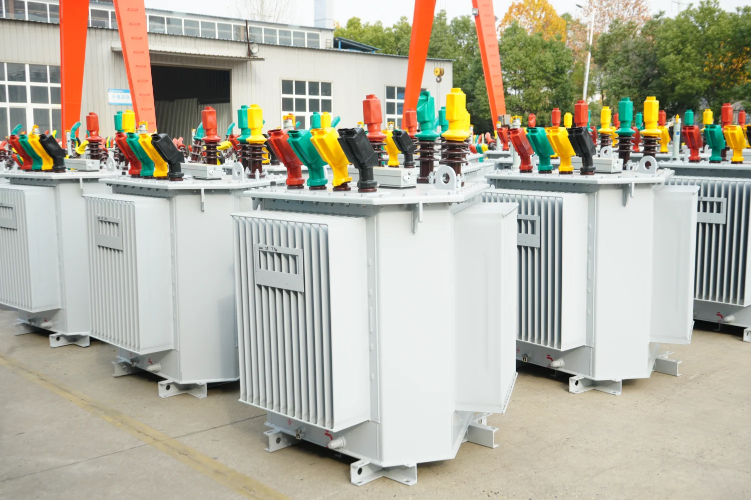
A three-phase transformer is a critical device in electrical power systems used for voltage conversion, power transmission, and energy distribution. Compared with single-phase transformers, a 3-phase transformer provides better load balance, improved efficiency, and reduced conductor material usage.
Three-phase transformers are widely applied in:
- Power transmission networks
- Industrial manufacturing plants
- Renewable energy systems
- Commercial buildings
- Utility distribution substations
Transformer capacity ranges from small units such as 15kVA transformers to large grid equipment exceeding 50000kVA.
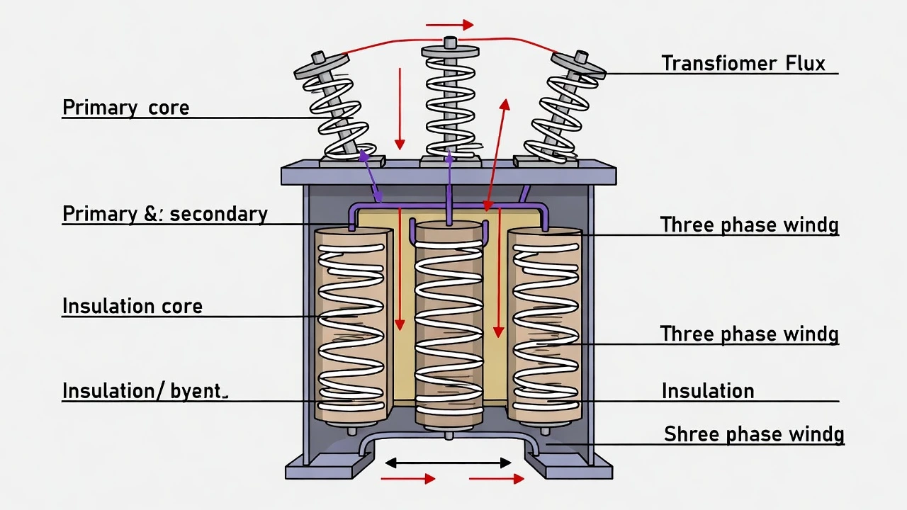
Basic Structure of a Three-Phase Transformer
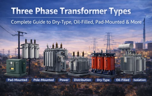
A three-phase transformer consists of three sets of windings connected to a shared magnetic core. These windings form various electrical configurations such as:
- Delta (Δ) connection
- Wye (Y) connection
- Delta-Wye transformer
Main Transformer Components
|
Component |
Function |
|
Magnetic core |
Provides a magnetic flux path |
|
Primary winding |
Receives electrical energy |
|
Secondary winding |
Supplies transformed voltage |
|
Insulation system |
Prevents electrical faults |
|
Dissipates operational heat |
Efficient magnetic flux transfer ensures minimal energy loss and stable transformer operation.
Three-Phase Transformer Voltage Specifications
Transformer voltage rating determines how electricity flows between transmission and distribution networks.
Typical Voltage Combinations
|
Primary Voltage |
Secondary Voltage |
Application |
|
11kV |
400V |
Utility distribution |
|
13.8kV |
480V |
Industrial plants |
|
22kV |
415V |
Commercial power systems |
|
33kV |
690V |
Renewable energy installations |
Voltage ratios are determined by the turns ratio between primary and secondary windings.
3 Phase Transformer kVA Chart (10kVA–50000kVA Full Table)
A 3-phase transformer kVA chart is widely used by electrical engineers to quickly estimate current ratings and load capacity. Three-phase transformers are manufactured in many different ratings to meet varying load requirements. This chart helps determine:
- Cable size selection
- Circuit breaker rating
- Power distribution planning
- Transformer load capacity
The current values below are calculated using the standard formula:
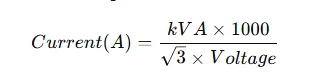
The table assumes a 400V three-phase system, which is common in industrial and commercial power distribution.
Three Phase Transformer kVA to Amps Chart
|
Transformer Size (kVA) |
Current (A) @ 400V |
Typical Application |
|
10kVA |
14 A |
Small equipment |
|
15kVA |
22 A |
Small commercial loads |
|
25kVA |
36 A |
Rural distribution |
|
30kVA |
43 A |
Residential power |
|
45kVA |
65 A |
Agricultural equipment |
|
50kVA |
72 A |
Small commercial systems |
|
75kVA |
108 A |
Office buildings |
|
100kVA |
144 A |
Small factories |
|
112.5kVA |
162 A |
Industrial equipment |
|
150kVA |
216 A |
Manufacturing plants |
|
200kVA |
288 A |
Commercial power systems |
|
225kVA |
325 A |
Shopping centers |
|
300kVA |
433 A |
Industrial loads |
|
400kVA |
577 A |
Manufacturing facilities |
|
500kVA |
721 A |
Industrial plants |
|
630kVA |
909 A |
Medium substations |
|
750kVA |
1082 A |
Large commercial buildings |
|
1000kVA |
1443 A |
Heavy industrial systems |
|
1250kVA |
1804 A |
Utility distribution |
|
1500kVA |
2165 A |
Large substations |
|
2000kVA |
2886 A |
Power distribution stations |
|
2500kVA |
3608 A |
Industrial substations |
|
3000kVA |
4330 A |
Utility power networks |
|
5000kVA |
7217 A |
Regional substations |
|
10000kVA |
14434 A |
High power transmission |
|
20000kVA |
28867 A |
Large power plants |
|
50000kVA |
72168 A |
Grid transmission systems |
How to Use the Transformer kVA Chart
Electrical engineers use this chart during power system design to quickly match transformer capacity with load demand.
Example
If a factory requires 600A of current at 400V, the chart indicates that a 400kVA transformer would be appropriate.
Practical Uses
|
Engineering Task |
How the Chart Helps |
|
Transformer sizing |
Match load demand |
|
Cable sizing |
Determine conductor capacity |
|
Circuit breaker selection |
Ensure safe operation |
|
Power system planning |
Estimate total load |
Using a 3-phase transformer kVA chart simplifies electrical design and helps prevent overloading or underutilizing transformers.
Transformer kVA Chart for Different Voltage Levels
Transformer current varies depending on the voltage level. Below is a quick comparison.
|
Transformer |
400V Current |
480V Current |
|
108A |
90A |
|
|
150A |
120A |
|
|
150kVA transformer |
216A |
180A |
|
300kVA transformer |
433A |
361A |
|
500kVA transformer |
721A |
601A |
|
1000kVA transformer |
1443A |
1202A |
Higher voltage systems result in lower current for the same power level, which reduces conductor losses.
Engineering Tip for Transformer Selection
When selecting a three-phase transformer, engineers usually add a 20–25% safety margin to accommodate:
- Future load expansion
- Power factor variations
- Temporary overload conditions
Example
If the calculated load is 300kVA, engineers may select a 400kVA transformer to ensure long-term reliability.
Transformer kVA to Current Calculator
Electrical engineers often need to calculate current based on transformer capacity.
Three-Phase Transformer Current Formula
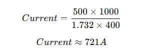
Example Calculation
For a 500kVA transformer operating at 400V:
Quick Calculation Table
|
Transformer Size |
Voltage |
Current |
|
75kVA transformer |
400V |
108A |
|
150kVA transformer |
400V |
216A |
|
300kVA transformer |
400V |
433A |
|
500kVA transformer |
400V |
721A |
|
1000kVA transformer |
400V |
1443A |
This calculator helps determine cable sizing, circuit protection, and load capacity.
Transformer Efficiency Comparison Table
Efficiency is an important parameter affecting operating costs.
Typical Transformer Efficiency
|
Transformer Size |
Efficiency |
|
30kVA transformer |
96% |
|
75kVA transformer |
97% |
|
150kVA transformer |
98% |
|
300kVA transformer |
98.5% |
|
500kVA transformer |
99% |
|
1000kVA transformer |
99.2% |
High-efficiency transformers significantly reduce energy losses in power distribution systems.
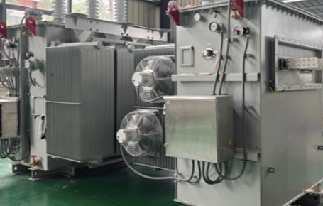
Transformer Cooling Methods
Effective cooling is essential to maintain transformer reliability and long service life.
Common Cooling Systems
|
Cooling Type |
Description |
|
ONAN |
Oil Natural Air Natural |
|
ONAF |
Oil Natural Air Forced |
|
OFAF |
Oil Forced Air Forced |
|
Dry Type |
Air-cooled transformer |
Dry-type transformers are often used indoors, while oil-filled transformers are preferred for high-capacity installations.
Transformer Price Reference Table
For international procurement, transformer pricing depends on capacity, materials, voltage level, and cooling type.
Estimated Transformer Price Range
|
Transformer Size |
Estimated Price Range |
|
30kVA transformer |
$600 – $1200 |
|
75kVA transformer |
$1200 – $2500 |
|
150kVA transformer |
$2500 – $4500 |
|
300kVA transformer |
$4500 – $8000 |
|
500kVA transformer |
$8000 – $15000 |
|
1000kVA transformer |
$15000 – $30000 |
|
2500kVA transformer |
$35000 – $80000 |
Prices vary depending on manufacturer specifications and export standards.
Industrial Applications of Three-Phase Transformers
Three-phase transformers are widely used across many industries.
Key Industrial Applications
|
Industry |
Transformer Use |
|
Manufacturing |
Equipment power supply |
|
Renewable energy |
Solar and wind farms |
|
Infrastructure |
Airports and railways |
|
Heavy machinery |
|
|
Reliable power distribution |
These transformers ensure stable voltage levels and reliable power delivery.
Key Factors When Selecting a Three-Phase Transformer
When selecting a transformer, engineers must evaluate several important parameters.
Transformer Selection Checklist
|
Factor |
Importance |
|
Rated capacity |
Must match load demand |
|
Voltage ratio |
Compatible with grid |
|
Cooling system |
Ensures safe operation |
|
Efficiency rating |
Reduces operating cost |
|
Installation environment |
Indoor or outdoor |
Proper selection improves system reliability and energy efficiency.
3 Phase Transformer Wiring Diagram Section
Understanding a three-phase transformer wiring diagram is essential for engineers, electricians, and installation technicians. Wiring configuration determines how voltage is transformed and how power is distributed across electrical loads.
Delta–Delta (Δ–Δ) Transformer Wiring Diagram
The Delta–Delta configuration connects both the primary and secondary windings in a triangular circuit.
Characteristics
- No neutral point
- Suitable for industrial power loads
- Provides redundancy if one winding fails
Delta–Delta Connection Table
|
Feature |
Description |
|
Primary connection |
Delta |
|
Secondary connection |
Delta |
|
Neutral availability |
No |
|
Typical voltage |
480V / 240V |
|
Applications |
Industrial machinery |
Delta connections are commonly used in high-power industrial systems where neutral grounding is not required.
Delta–Wye (Δ–Y) Transformer Wiring Diagram
The Delta–Wye transformer is the most widely used configuration in power distribution systems.
Advantages
- Provides a neutral point
- Allows both single-phase and three-phase loads
- Improves voltage stability
Delta–Wye Transformer Wiring Parameters
|
Parameter |
Description |
|
Primary side |
Delta connection |
|
Secondary side |
Wye connection |
|
Phase shift |
30° |
|
Voltage conversion |
High voltage to distribution voltage |
|
Typical application |
Utility distribution networks |
Many 11kV/400V distribution transformers use this wiring configuration.
Wye–Wye (Y–Y) Transformer Wiring Diagram
The Wye–Wye configuration connects both primary and secondary windings in star formation.
Key Features
- Provides neutral on both sides
- Suitable for long-distance power transmission
- Allows grounding of both systems
Wye–Wye Transformer Characteristics
|
Feature |
Description |
|
Primary winding |
Wye connection |
|
Secondary winding |
Wye connection |
|
Neutral availability |
Yes |
|
Voltage stability |
Moderate |
|
Application |
Transmission networks |
However, this configuration may require additional grounding transformers to maintain stability.
Comparison of Three-Phase Transformer Wiring Methods
Different wiring diagrams offer distinct advantages depending on system requirements.
Transformer Wiring Configuration Comparison
|
Configuration |
Neutral |
Phase Shift |
Typical Use |
|
Delta–Delta |
No |
0° |
Industrial loads |
|
Delta–Wye |
Yes |
30° |
Distribution systems |
|
Wye–Wye |
Yes |
0° |
Transmission systems |
Among these, Delta–Wye transformers are the most common for commercial power distribution.
Practical Installation Considerations
When installing a three-phase transformer, engineers must follow several key practices.
Installation Checklist
|
Factor |
Requirement |
|
Phase sequence |
Must match the supply system |
|
Grounding |
Required for safety |
|
Voltage verification |
Confirm primary/secondary ratings |
|
Insulation test |
Perform before energizing |
|
Load balancing |
Ensure equal phase load |
Correct installation ensures stable operation and long transformer life.
Typical Applications of 3 Phase Transformer Wiring
Three-phase transformer wiring is used across many industries.
Industry Applications
|
Industry |
Transformer Use |
|
Manufacturing |
Machinery power supply |
|
Renewable energy |
Solar and wind power |
|
Infrastructure |
Airports and railways |
|
Data centers |
Reliable electrical supply |
|
Commercial buildings |
Power distribution |
These wiring configurations allow transformers to deliver reliable and efficient electrical power.
The three-phase transformer is an essential component of modern electrical infrastructure. From small units such as 15kVA transformers to large 2500kVA and 50000kVA power transformers, these devices support industrial operations, commercial power distribution, and renewable energy systems. Understanding transformer capacity, voltage specifications, efficiency, and sizing calculations enables engineers and procurement professionals to select the most suitable transformer model.
Related Articles

Related Products
100kVA Single Phase Pad Mounted Transformer
The 100 kVA Single Phase Pad Mounted transformer adheres to a compartmental-type structure in line with IEEE Std C57.12.28 or IEEE Std C57.12.29 standards. It consists of a tank housing high-voltage and low-voltage cable terminating compartments, thoughtfully positioned side by side along one face of the transformer tank. In this configuration, the high-voltage compartment, fitted with two internally connected high-voltage bushing wells and inserts, a 4-position loadbreak switch, a 5-position tap changer switch, and a bayonet fuse, is situated alongside the low-voltage compartment featuring three stud L.V bushings and an oil level gauge.
300kVA Oil Immersed Transformer
In the field of power transmission and distribution, NPC ELECTRIC 300kVA oil-immersed transformer stands out with its excellent performance, providing reliable power support for various power consumption scenarios. The transformer is carefully wound with high-quality silicon steel sheets and electromagnetic wires, with extremely low no-load loss and load loss, which greatly improves the efficiency of power conversion and effectively reduces electricity costs. It is widely used in industrial plants, commercial centers, residential communities, infrastructure construction, and other fields to meet the power needs of different scenarios.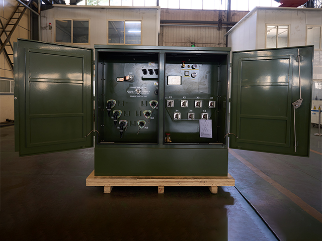
167kVA Three Phase Pad Mounted Transformer
The 167kVA three phase pad mounted transformer delivers robust and efficient power distribution for medium-voltage applications. Built to exceed ANSI C57.12.34, IEEE, and DOE efficiency standards, this compartmental-type unit features a durable, tamper-resistant steel enclosure with dead-front or live-front high-voltage bushings, radial or loop feed configurations, and a 65°C average winding rise for optimal thermal performance. Primary voltages range from 4160V to 34500V (with common options like 12470GrdY/7200 or 13800V), while secondary voltages include 208Y/120V, 480Y/277V, or custom low-voltage setups.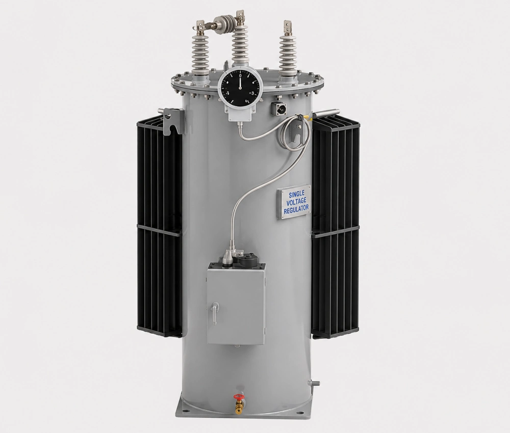
SVR-3 Type Feeder Automatic Step Voltage Regulator
The SVR-3 Type Feeder Automatic Step Voltage Regulator is an advanced, three-phase on-load automatic voltage regulation system designed specifically for distribution feeders. Equipped with a high-speed motorized on-load tap changer, premium copper windings, and low-loss silicon steel core, it delivers precise and rapid voltage stabilization with minimal waveform distortion. The intelligent microprocessor controller continuously monitors line voltage and automatically adjusts taps to maintain stable output voltage, even under rapidly changing load conditions. Built for harsh outdoor environments, the SVR-3 features a fully sealed oil-immersed tank with excellent corrosion protection, advanced cooling system, and comprehensive protection functions including over-voltage, under-voltage, overload, short-circuit, and reverse power protection. With remote monitoring capability and high overload capacity, the SVR-3 significantly improves power quality, reduces energy losses, and enhances reliability across distribution networks.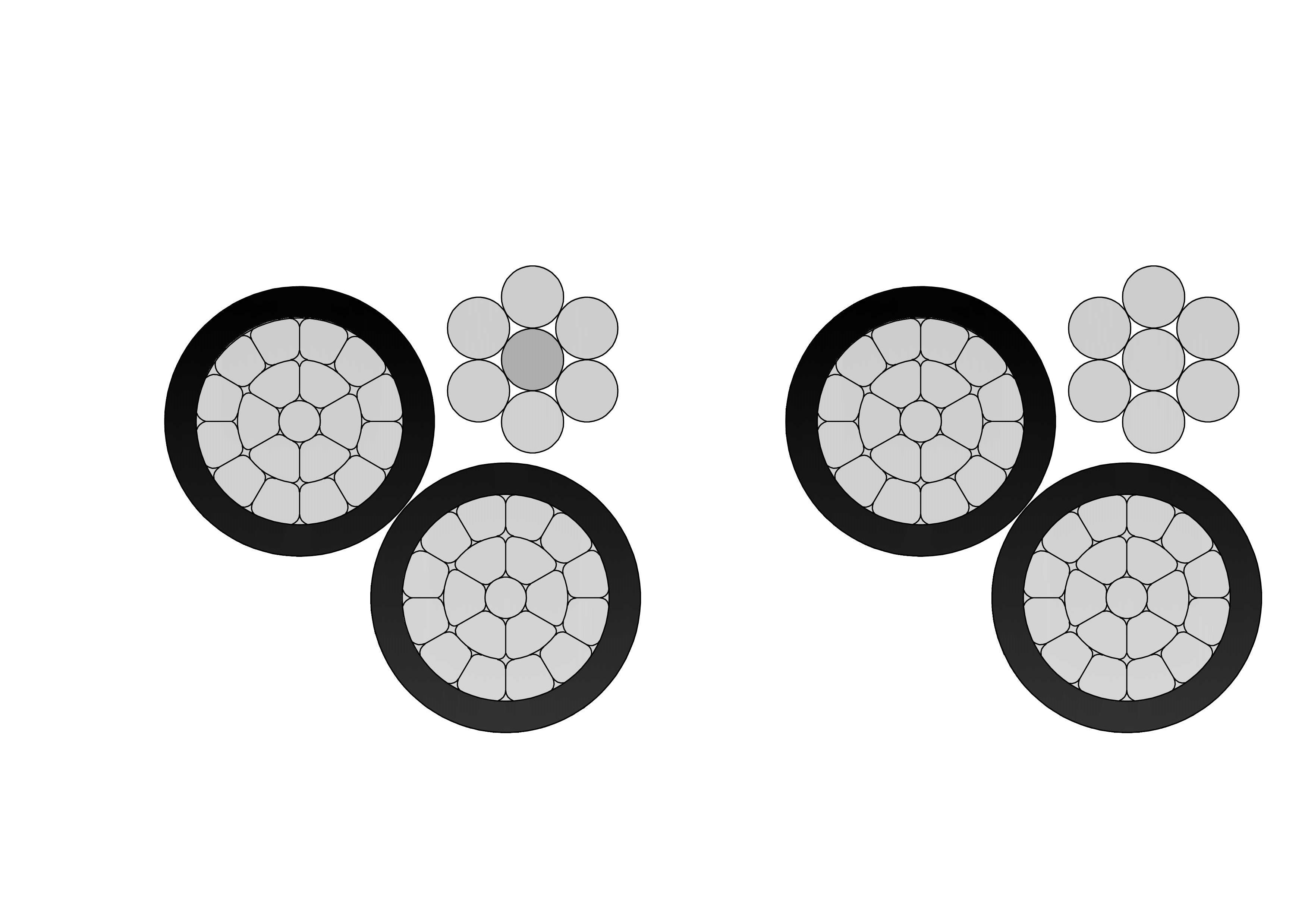
1/0 Gammarus Aluminum Conductor Triplex Overhead Service Drop Cable
NPC Electric 1/0 Gammarus Triplex Service Drop Cable provides reliable overhead secondary distribution for residential applications. Consisting of two 1/0 AWG aluminum phase conductors and one neutral messenger (7-strand) insulated with cross-linked polyethylene (XLPE) and twisted in triplex form, it meets ASTM, ICEA, and international standards. The robust insulation resists sunlight, moisture, and mechanical damage for decades of outdoor service. Lightweight design simplifies installation with low sag and easy handling. The 1/0 Gammarus Triplex Service Drop Cable ensures minimal losses, high current capacity, and excellent weather performance up to 600V. Self-supporting messenger reduces pole loading. Flame-retardant options enhance safety. Commonly chosen for two-phase power delivery with neutral in subdivisions, rural homes, and temporary connections requiring safe, economical aerial bundled solutions with proven durability.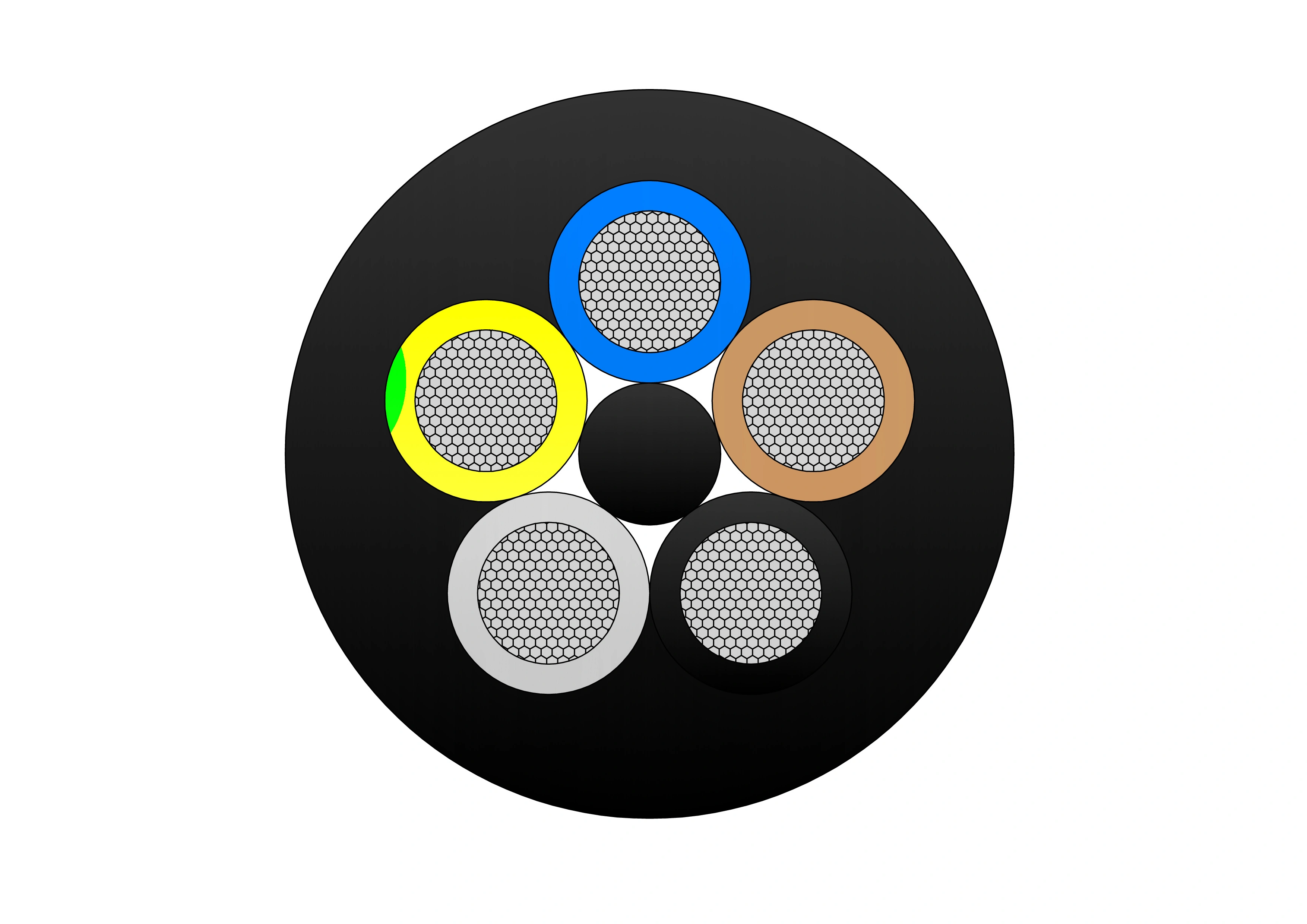
Type 450 Flexible Copper Screened Mining Cable With Two Earth And One Pilot Core
The Type 450 Flexible Copper Screened Mining Cable is a medium-voltage, heavy-duty mining cable designed for power supply in draglines, slow reeling, and industrial applications requiring two earth cores and one pilot core. It features tinned annealed copper conductors, EPR (XR-EP-90) insulation, and a tinned copper/polyamide braid screen for electrical shielding. The double-layer HD-PCP sheath provides extra heavy-duty protection, including oil resistance, flame retardancy, and chemical durability. Available in voltage ratings from 3.3kV to 33kV, the cable meets AS/NZS 2802 and related standards, ensuring high performance and reliability in harsh mining environments.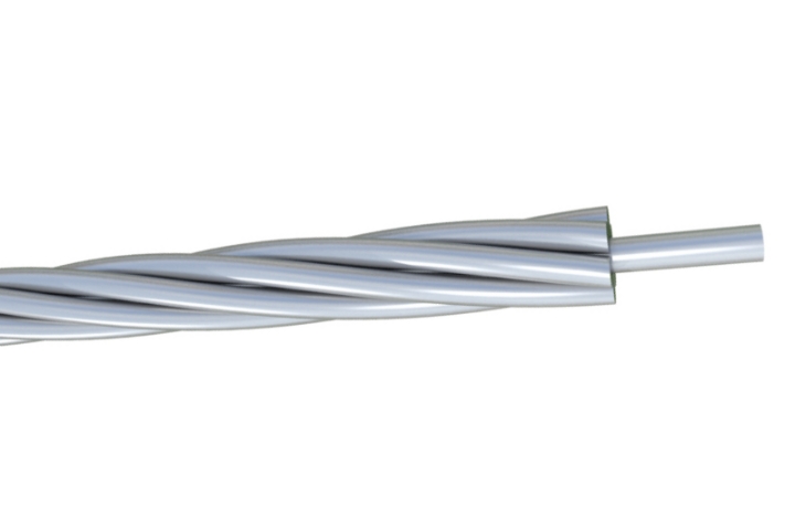
10 Gauge Galvanized Steel Conductor Wire
The 10 Gauge Galvanized Steel Conductor Wire is a premium high-strength bare steel wire designed for reliable overhead power line applications. Manufactured with heavy hot-dip zinc coating, this 10 AWG galvanized conductor delivers superior corrosion resistance and long service life in harsh outdoor environments. It offers excellent tensile strength and mechanical performance, making it ideal for use as overhead ground wire (static wire), guy wire, or messenger wire. Fully compliant with ASTM A475 and related utility standards, the 10 Gauge Galvanized Steel Conductor Wire undergoes rigorous testing from raw materials to finished product to ensure uniform zinc adhesion, consistent diameter, and high breaking strength. Its durable construction minimizes maintenance while providing dependable shielding and structural support for transmission and distribution systems.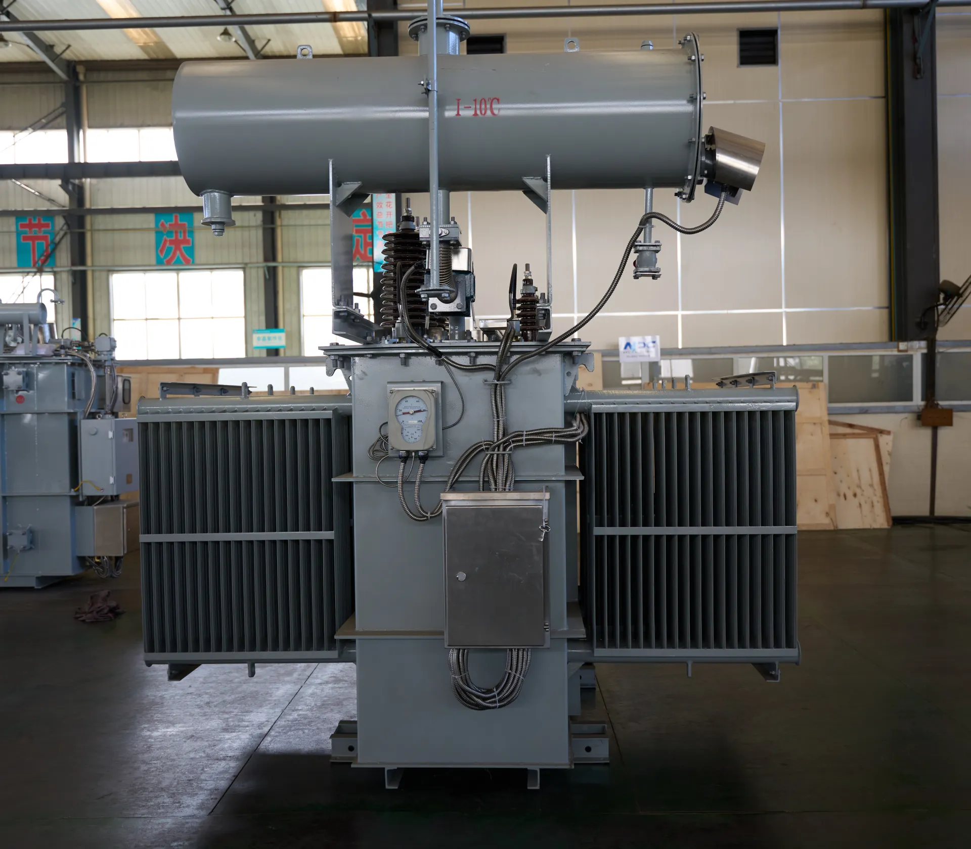
630kVA Three-Phase Oil-Immersed Outdoor Substation Transformer | 220V to 380V Step-Up Transformer
This 630kVA three-phase oil-immersed transformer is designed for outdoor substations, providing reliable voltage conversion from 220V to 380V. With a robust oil-immersed cooling system, it ensures excellent heat dissipation, stable performance, and long service life. Ideal for industrial facilities, commercial power distribution, and utility applications, this step-up transformer delivers consistent efficiency even under heavy load conditions.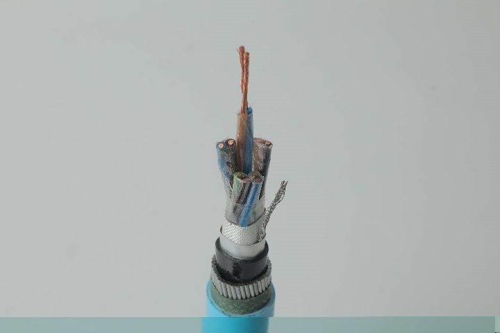
Instrumentation Cables—XLPE Insulated, Overall Screened, Wire Armoured PVC Sheathed Cables(CU/XLPE/OSCR/SWA/PVC)
Engineered for thermal resilience and electromagnetic shielding, the Instrumentation Cables—XLPE Insulated, Overall Screened, Wire Armoured PVC Sheathed Cables (CU/XLPE/OSCR/SWA/PVC) excel in high-temperature environments. Stranded copper conductors ensure low resistance and flexibility, with XLPE insulation providing 90°C continuous rating and 250°C short-circuit tolerance. Overall screening via aluminum/polyester tape and drain wire mitigates EMI/RFI, preserving signal quality. SWA armour protects against mechanical damage, while PVC sheath adds flame resistance and waterproofing. Meeting BS EN 50288-7 and BS EN 50288-1 standards, these multi-pair cables transmit analogue/digital signals with low capacitance in demanding circuits. Suitable for ducts, trays, direct burial, or outdoor exposures, they boost system integrity and reduce interruptions in heat-intensive areas. With enhanced dielectric properties and attenuation control, this CU/XLPE/OSCR/SWA/PVC offers dependable, maintenance-reducing solutions for professionals in petrochemical, power, and industrial sectors.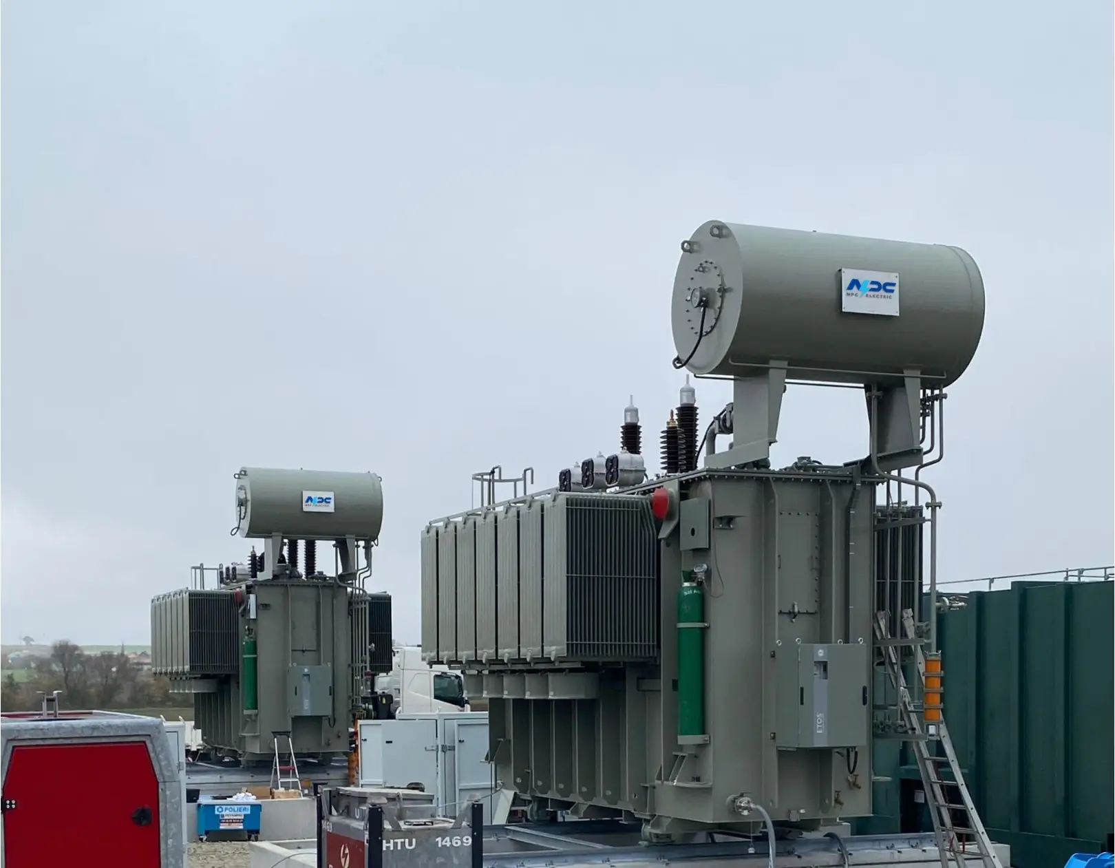
65kV Three-Phase Oil-Immersed Power Transformer with No-Load Voltage Regulation
The 65kV Three-Phase Oil-Immersed Power Transformer with No-Load Voltage Regulation is engineered for medium-to-high voltage distribution systems requiring stable performance and precise voltage control. Equipped with a no-load tap changer, the transformer allows flexible adjustment of voltage ratios to meet varying grid demands. Its high-grade silicon steel core and oxygen-free copper windings ensure low losses, superior thermal efficiency, and long operational life. The oil-immersed cooling system provides enhanced heat dissipation, while the durable outdoor-rated tank structure enables reliable operation in harsh climatic environments. Designed in compliance with IEC, IEEE, and GB standards, this transformer is widely used in utility substations, industrial power networks, renewable energy stations, and large commercial distribution systems. It delivers consistent voltage regulation, strong overload capability, and dependable long-term grid support.
250kVA Three Phase Pad Mounted Transformer
The 250kVA Three Phase Pad Mounted Transformer is a compact, liquid-immersed, self-cooled (ONAN) distribution transformer optimized for efficient, underground power delivery in residential, light commercial, and small industrial applications. Fully compliant with IEEE C57.12.34, ANSI C57.12.00, DOE 2016 efficiency standards, and UL-listed, this compartmental-type unit features dead-front 200A high-voltage bushing wells (loadbreak inserts), radial or loop feed options, and a sealed tank using non-PCB mineral oil or FR3 natural ester fluid for improved fire safety and environmental performance.
600/1000V PVC Insulated Cable to IEC 60502-1 Standard
The 600/1000V PVC Insulated Low Voltage Power Cable is designed for reliable power transmission in low-voltage electrical systems. Manufactured with high-quality copper or aluminum conductors and PVC insulation, this cable provides stable electrical performance, good flexibility, and long service life. The PVC insulation offers effective protection against moisture, abrasion, oils, and common chemicals, making the cable suitable for both indoor and outdoor installations. Rated at 600/1000 volts, the cable ensures safe and efficient power distribution under normal operating conditions. Its robust insulation structure supports consistent current flow while maintaining electrical safety. The cable is easy to install, route, and terminate, making it a practical solution for residential, commercial, and industrial power networks. With dependable insulation performance and mechanical durability, this low voltage power cable meets the demands of everyday electrical infrastructure.
35kV Concentric Neutral Underground Power Cable
The 35 kV Concentric Neutral Power Cable is a high-performance medium-voltage underground cable designed for primary distribution systems. It features a stranded conductor, semi-conducting shields, tree-retardant TR-XLPE or EPR insulation, helically applied bare copper concentric neutral wires, and a sunlight-resistant LLDPE jacket. This construction provides excellent electrical performance, superior resistance to water treeing, and robust mechanical protection suitable for direct burial or duct installations. Available in various conductor sizes and insulation levels, the cable ensures safe and efficient power delivery. Manufactured to the latest ICEA S-94-649 and AEIC CS8 standards, the 35 kV Concentric Neutral Power Cable undergoes extensive quality testing to deliver consistent low dielectric loss and long service life in demanding underground environments.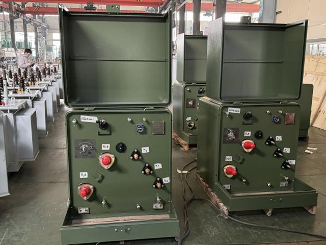
167kVA Conventional Type Single Phase Pole Mounted Transformer
NPC ELECTRIC'S 167kVA Single Phase pole Mounted transformer is a high capacity single phase distribution transformer designed for medium to high load distribution systems. It is mainly used in residential, commercial, agricultural and light industrial applications to provide stable single phase power to ensure reliable operation of user-side equipment. It complies with international standards such as ANSI/IEEE C57, IEC60076 and other standards to ensure its high quality and stability. Standard features include mineral oil insulation (ONAN cooling), aluminum or copper windings, primary voltages 2.4kV–34.5kV grounded wye or delta (common: 7200/12470GrdY, 7620/13200GrdY, 12470GrdY/7200, 24940GrdY/14400, 34500GrdY/19920), secondary 120/240V or 240/120V split-phase (options for 277V/480V or custom), BIL ratings 95–150kV HV / 30kV LV, impedance typically 1.5–4.5%, ±2×2.5% or 5-position tap changer, conventional or CSP (completely self-protected) configurations with internal fuses, lightning arresters, weak-link protection, pressure relief valve, oil sight gauge, and ANSI 70 gray tank finish. Efficiency typically reaches 99.33% at 50% load per DOE levels (with 2029 amendments targeting further reductions for units ≥100 kVA), with low sound levels and corrosion-resistant hardware for extended outdoor service.
2000 MCM Cowslip AAC All Aluminum Bare Conductor Cable
The 2000 MCM Cowslip AAC Cable represents premium All Aluminum Conductor technology for overhead power applications. Built with 91 strands of high-conductivity 1350-H19 aluminum, this bare conductor delivers an optimal balance of electrical efficiency and mechanical robustness. With a 1.631-inch diameter, 32,200 lbs breaking strength, and 1518 amps ampacity, the Cowslip AAC offers low DC resistance of 0.00864 ohms per 1000 ft at 20°C and a weight of 1877 lbs per 1000 ft. This design minimizes sag while providing excellent corrosion resistance for extended outdoor service. Manufactured to meet ASTM B-230 and B-231 standards, the 2000 MCM Cowslip AAC Cable undergoes extensive quality testing from raw materials through finished product. It is the ideal solution for new installations and upgrades in transmission and distribution systems that demand lightweight, high-conductivity bare aluminum conductors.Welcome your inquiry
Honesty, Integrity, Frugality, Activeness and Passion