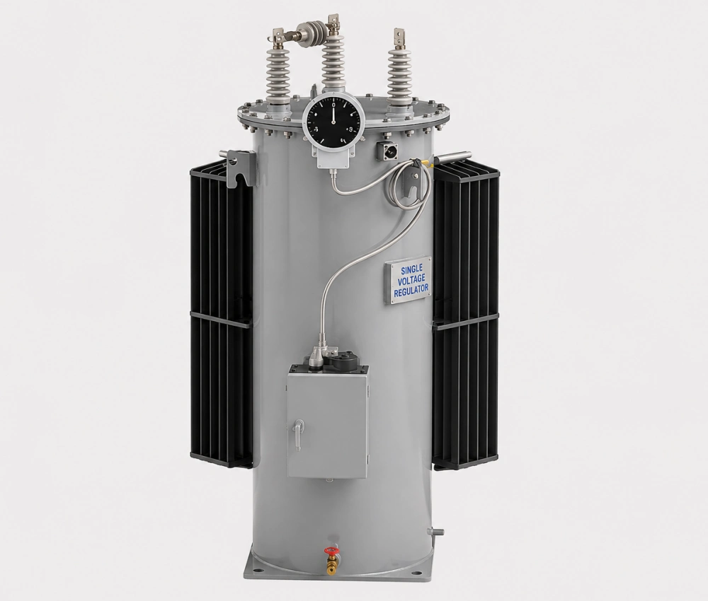
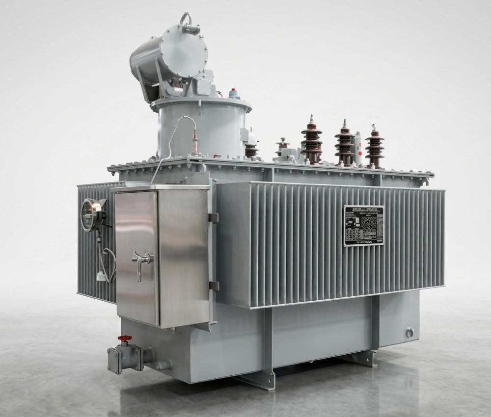
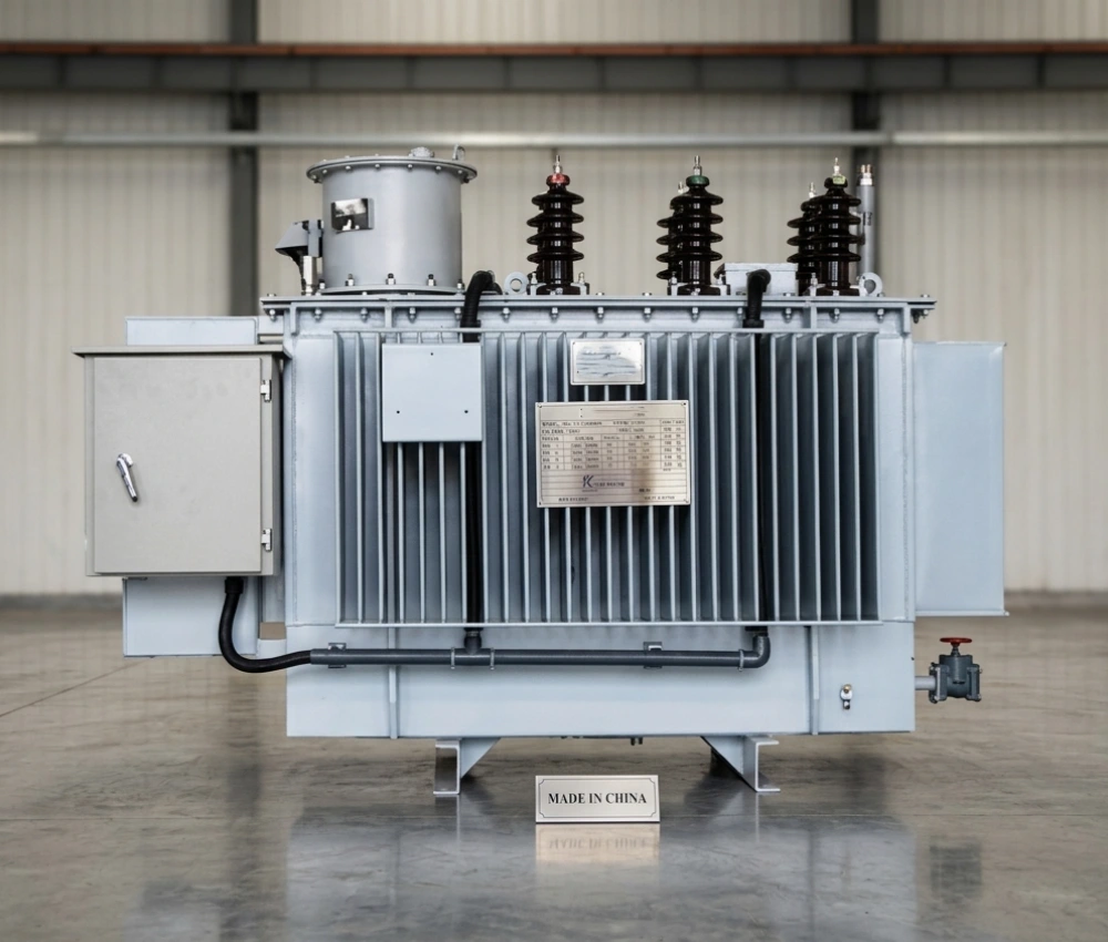


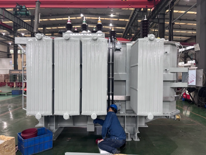
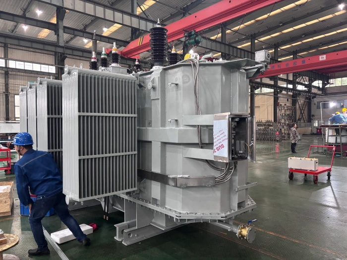
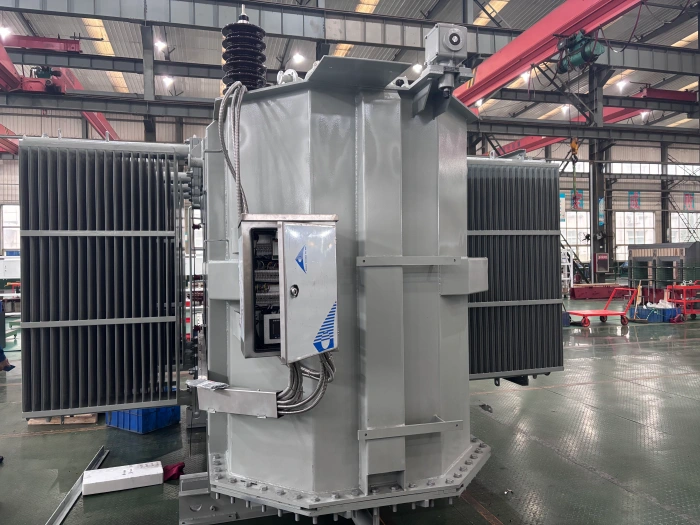
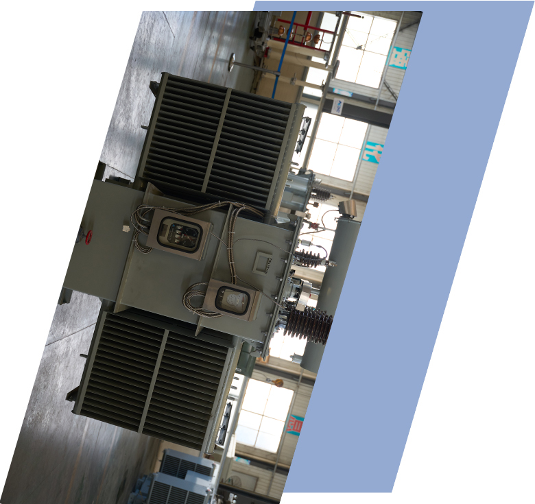
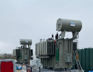
SVR-3 Type Feeder Automatic Step Voltage Regulator
The SVR-3 Type Feeder Automatic Step Voltage Regulator is an advanced, three-phase on-load automatic voltage regulation system designed specifically for distribution feeders. Equipped with a high-speed motorized on-load tap changer, premium copper windings, and low-loss silicon steel core, it delivers precise and rapid voltage stabilization with minimal waveform distortion. The intelligent microprocessor controller continuously monitors line voltage and automatically adjusts taps to maintain stable output voltage, even under rapidly changing load conditions. Built for harsh outdoor environments, the SVR-3 features a fully sealed oil-immersed tank with excellent corrosion protection, advanced cooling system, and comprehensive protection functions including over-voltage, under-voltage, overload, short-circuit, and reverse power protection. With remote monitoring capability and high overload capacity, the SVR-3 significantly improves power quality, reduces energy losses, and enhances reliability across distribution networks.
- Primary Voltage Ratings 11 kV / 22 kV / 33 kV
- Secondary Voltage Ratings --
- H.V. Tap Range --
- Type Voltage Regulator
- BIL 11kV - 200kV
- Standards IEC 60076, IEC 60137, ASTM D202
- Application distribution networks, renewable energy integration
- Power Rating --
- Certificate UL, CESI, IEEE
- Cooling Method ONAN/ ONAF
- Opeartion --
Technical Specifications
Customization Optional
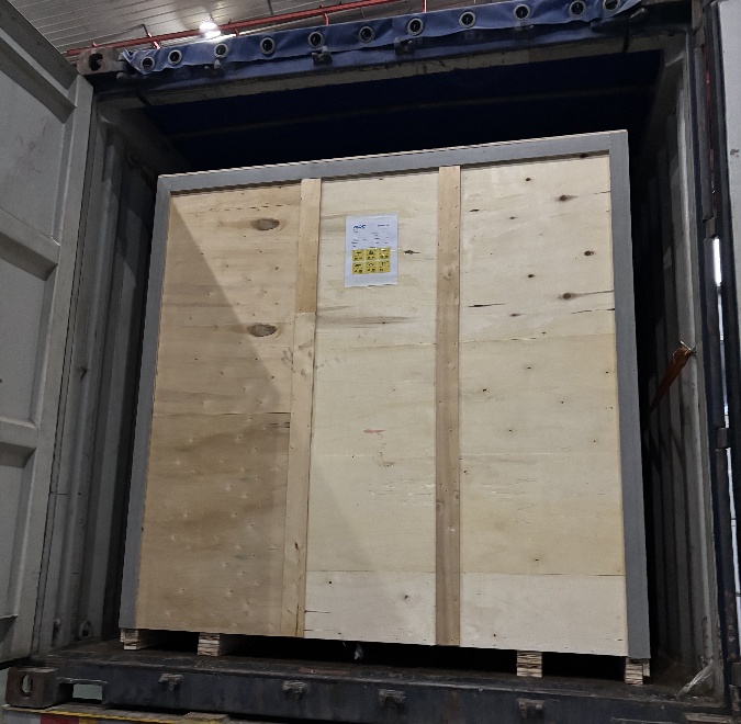
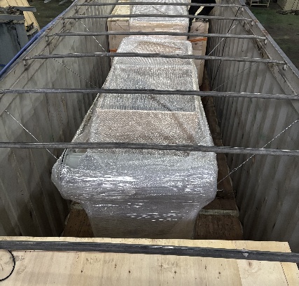
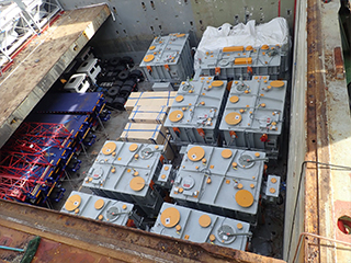
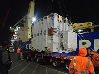
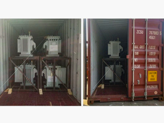
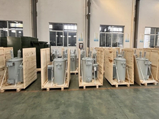
Packing and Shipping
Manufacturer Test
Routine Testing
Application
Technical Specifications
SVR-3 Type Feeder Automatic Step Voltage Regulator
SVR-3 Type Feeder Automatic Step Voltage Regulator Parameter
| Parameter | Specification |
| Rated Capacity | 100 kVA – 2500 kVA |
| Rated Voltage | 11 kV / 22 kV / 33 kV |
| Regulation Range | ±10% ~ ±20% (32 steps) |
| Step Voltage | 0.625% / 0.75% per step |
| Response Time | ≤ 1.5 seconds |
| Cooling Method | ONAN / ONAF |
| Short Circuit Withstand | 25 kA / 2 seconds |
| Ambient Temperature | -40°C to +55°C |
Customization Optional
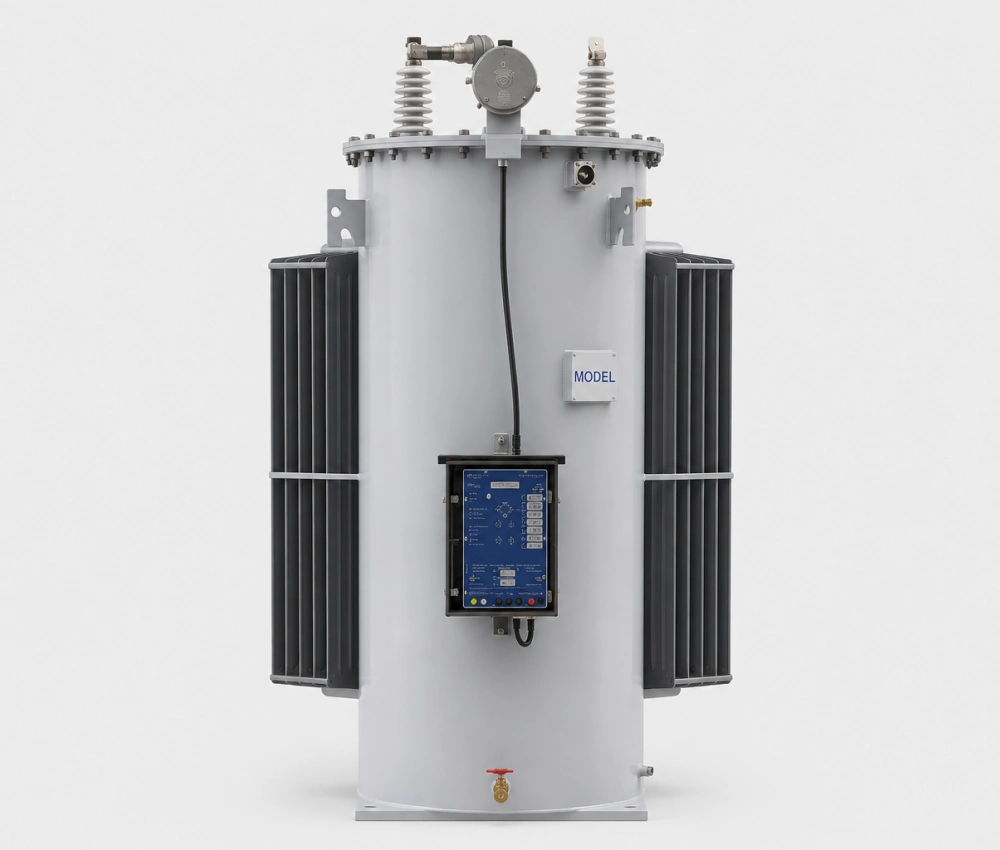
SVR-3 Type Feeder Automatic Step Voltage Regulator
The SVR-3 Type Feeder Automatic Step Voltage Regulator can be fully customized to match specific feeder characteristics and environmental requirements. Customers can select rated voltage (6–36 kV), capacity (100–2500 kVA), regulation range (±10% to ±25%), and number of tap steps (16–40 steps). Control systems support various protocols including IEC 61850, DNP3, Modbus, and 4G/GPRS remote monitoring for seamless SCADA integration. We offer enhanced overload designs (up to 200% for 2 hours), low-noise configurations for urban areas, and high-corrosion-resistant stainless steel tanks for coastal or heavily polluted environments.
Additional customization includes automatic power factor correction integration, harmonic filtering, solar-powered backup controllers for remote sites, bypass switch arrangements, and programmable voltage set points with time-of-day scheduling. Enclosure options range from compact pole-mounted to pad-mounted or substation frame-mounted designs with advanced bird and animal protection. These flexible options allow utilities to deploy the most suitable SVR-3 regulator for improving voltage profile, reducing line losses, and enhancing overall distribution system efficiency.
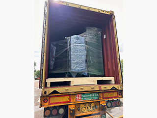
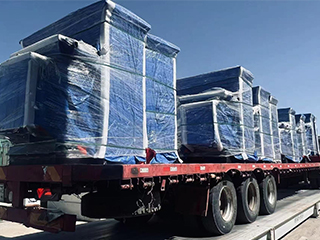
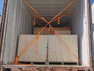
Packing and Shipping
SVR-3 Type Feeder Automatic Step Voltage Regulator
The SVR-3 Type Feeder Automatic Step Voltage Regulator is packaged with robust protection to ensure safe delivery even under challenging transport conditions. The unit is securely mounted on a heavy-duty reinforced wooden pallet with anti-vibration rubber blocks and multiple high-tensile steel strapping bands. All bushings, radiators, and the control cabinet are individually braced with custom wooden frames and high-density foam padding. The complete assembly is wrapped in multi-layer waterproof film and moisture-absorbent materials, then enclosed in a sturdy, ISPM 15 fumigated wooden crate or steel-reinforced container frame with clear shock and tilt indicators for full transit visibility.
We provide flexible shipping solutions tailored to project urgency and location. Sea freight in 20ft or 40ft open-top/flat-rack containers with professional blocking and lashing offers economical and secure international transport, typically 25–60 days. Air freight is arranged for urgent spare parts or emergency replacements. Domestic and regional shipments use specialized low-bed trailers equipped with hydraulic loading systems and GPS tracking.
Complete export documentation packages are prepared in advance, including commercial invoices, packing lists, certificates of origin, factory test reports, and detailed installation manuals to ensure fast customs clearance. We prioritize sustainable practices by using recyclable materials and optimizing container loading to reduce environmental impact. Customers receive a secure online tracking system with real-time updates and dedicated logistics coordinator support.
Upon delivery, we offer optional professional supervision for unloading, oil level verification, and initial site inspection. For large-scale projects, consolidated multi-unit shipments and phased delivery scheduling are available to minimize site congestion and logistics costs. This comprehensive packing and shipping process guarantees that every SVR-3 regulator arrives in perfect condition, ready for immediate installation and commissioning.
32
32 years of industry experience
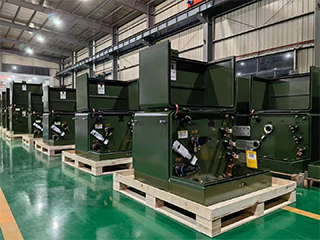
Manufacturer Test
SVR-3 Type Feeder Automatic Step Voltage Regulator
Progress Test
Early manufacturing progress testing of the SVR-3 regulator includes core material validation through Epstein frame and watt-loss testing to ensure superior magnetic performance. Copper winding resistance, insulation resistance, and dielectric withstand tests are conducted on each coil before assembly. The motorized on-load tap changer undergoes rigorous mechanical endurance cycling exceeding 15,000 operations to verify smooth switching and contact reliability. Tank welding quality is inspected using helium leak detection and radiographic testing. Initial control system calibration checks voltage sensing accuracy, protection thresholds, and communication modules. These foundational tests, recorded digitally with full traceability, establish mechanical and electrical integrity from the initial production stages. Oil dehydration, degassing, and vacuum filling processes are strictly monitored for moisture content and dielectric strength. The automatic regulation logic is simulated across full input voltage and load ranges to verify step accuracy and response time.
Design Tests
All transformer will be test after finished the production, test items as below:
♦ Insulation Power Factor
♦ Ratio, Polarity, and Phase Relation
♦ Winding Resistance
♦ Impulse Tests
♦ On load Loss Test
♦ No Load Loss Test
♦ Transformer Turns Ratio/TTR (All Tap Voltages)
♦ Impedance Voltage & Load Loss (Rated Voltage)
♦ Polarity, 1-Ph / Phase Relation, 3-Ph (Rated Voltage)
♦ Excitation & No-Load Loss (Rated Voltage)
♦ Applied Voltage
♦ Induced Voltage
♦ Lightning Impulse
♦ Insulation Resistance (Rated Voltage)
♦ Temperature Rise
♦ Dielectric Withstand (Hipot)
Factory Acceptance Test
Factory Acceptance Testing for the SVR-3 Type regulator begins with precise ratio, polarity, and impedance measurements across all tap positions. No-load loss and excitation current tests confirm core efficiency. Full-range automatic regulation accuracy and response time are verified under zero to full load conditions using precision test equipment. All protection functions (over/under voltage, overload, short-circuit, reverse power) are activated and validated for timing and reliability. Control system calibration, display accuracy, alarm functions, and remote communication protocols are thoroughly tested. These essential electrical and functional tests are fully documented with waveforms and data sheets. On-load tap changer endurance testing under simulated load confirms long-term mechanical and electrical reliability. Harmonic distortion, power factor, and regulation stability are measured under different load types.
Routine Test - Induced Voltage
Purpose of Testing
The purpose of the Induced Voltage test is to simulate the electrical stress that the equipment may encounter under actual working conditions by applying an induced voltage, thereby evaluating the tolerance and stability of the equipment's insulation system. This test helps to detect the insulation performance of the equipment under high voltage conditions and ensure its safety and reliability in operation.
Testing Equipment
Induced Voltage Tester (e.g. OMICRON, Megger, HioKI, etc.)
AC voltage source, commonly 2 kV, 5 kV, 10 kV, or customized according to test requirements.
Environmental thermometer and hygrometer, used to record the temperature and humidity of the environment for appropriate test evaluation.
AC voltage source, commonly 2 kV, 5 kV, 10 kV, or customized according to test requirements.
Environmental thermometer and hygrometer, used to record the temperature and humidity of the environment for appropriate test evaluation.
Pre-Test Preparation
Disconnect all relevant power supplies and ensure that the equipment is properly grounded and discharged.
Check the connection wires and terminals to ensure they are secure and free of contamination.
Test under suitable environmental conditions: relative humidity below 75%, no rain (recommended temperature: 20-30°C).
Check the connection wires and terminals to ensure they are secure and free of contamination.
Test under suitable environmental conditions: relative humidity below 75%, no rain (recommended temperature: 20-30°C).
Test Progress
Connect the Test Instrument:
Connect the test equipment to the appropriate terminals or bushings of the device under test, ensuring that the connections are secure and properly grounded.
Apply Test Voltage:
Select the appropriate induction voltage according to the rated voltage and standard of the equipment.
Connect the test equipment to the appropriate terminals or bushings of the device under test, ensuring that the connections are secure and properly grounded.
Apply Test Voltage:
Select the appropriate induction voltage according to the rated voltage and standard of the equipment.
Measure and Record
Start the test and record the following parameters:
Induced Voltage
Applied Current
Voltage peak, stability and waveform (waveform analysis)
Any abnormal current or voltage changes during the measurement process.
Induced Voltage
Applied Current
Voltage peak, stability and waveform (waveform analysis)
Any abnormal current or voltage changes during the measurement process.
Temperature Correction
The measured induced voltage data is corrected to the reference temperature (usually 20°C) to ensure the accuracy of the test results.
Repeat Testing (if necessary)
If necessary, test different windings (HV, MV, LV) and bushings separately and compare the results at different test points.
Evaluation Criteria (Reference)
Inductive voltage ≤ 1% (Excellent): normally and meets safety standards.
1% < Inductive voltage ≤ 3% (Good): still within acceptable range.
Inductive voltage > 3% : faulty or not meet safety requirements and requires further analysis and repair.
1% < Inductive voltage ≤ 3% (Good): still within acceptable range.
Inductive voltage > 3% : faulty or not meet safety requirements and requires further analysis and repair.
*These comprehensive tests ensure that each transformer meets performance standards and operates
reliably under various conditions.
Application
Extensively deployed in utility distribution networks, renewable energy integration points, and industrial park feeders, providing reliable automatic voltage regulation for both overhead lines and substation applications to enhance power quality and operational efficiency.


Technical Advantages
● 30+ years of manufacturing experience
● ISO and UL certified production
● Customized cable and transformer solutions


Product Packaging
Transformers Packaging (1)
Transformers Packaging (2)
Transformers Packaging (3)
Transformers Packaging (4)
Transformers Packaging (5)
Transformers Packaging (6)
Transformers Packaging (7)
Transformers Packaging (8)
Related Products
121kV Oil-Immersed High-Voltage Power Transformer
The 121kV Oil-Immersed High-Voltage Power Transformer is designed to provide stable, efficient, and long-term power transformation for transmission networks and high-voltage substations. Utilizing high-quality silicon steel cores and precision-wound copper conductors, the transformer achieves low no-load losses, strong short-circuit withstand capability, and excellent thermal stability. The oil-immersed insulation and cooling system ensures effective heat dissipation, supporting continuous operation under heavy-load and fluctuating grid conditions. Its reinforced tank structure, advanced insulation system, and outdoor-rated protection design enable reliable performance in harsh climates and demanding environments. Manufactured in accordance with IEC, IEEE, and ANSI standards, this transformer is widely applied in utility grids, industrial power systems, and infrastructure projects requiring high reliability, safety, and long service life.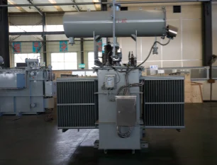
11kV Three-Phase Oil-Immersed Power Transformer
The 11kV Three-Phase Oil-Immersed Power Transformer is engineered for stable and efficient distribution across medium-voltage networks. Designed with high-grade silicon steel, advanced insulation systems, and premium mineral oil, this transformer ensures superior dielectric strength, excellent heat dissipation, and long service life. Its oil-immersed configuration delivers reliable cooling performance, enabling continuous operation under varying load conditions. The three-phase design ensures balanced power delivery, reduced energy losses, and improved grid stability. With enhanced short-circuit strength, low noise levels, and robust mechanical structure, it is suitable for industrial facilities, commercial complexes, substations, and utility distribution networks. Custom voltage ratios, tap changers, protection devices, and enclosure options are available to meet regional standards and project-specific requirements.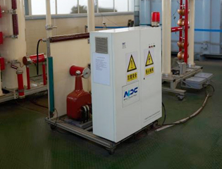
250kVA Dry Type Cast Resin Transformer 10kV/0.4kV Copper Core | CE/IEC/UL
Introducing the premium 250kVA Dry Type Cast Resin Transformer 10kV/0.4kV Copper Core, a high-performance, maintenance-free solution engineered for safe and efficient indoor power distribution. Featuring fully vacuum-cast epoxy resin windings with premium copper conductors, this three-phase transformer delivers exceptional low-loss performance, reduced no-load and load losses, and outstanding energy efficiency often surpassing 98%. The cast resin encapsulation provides superior moisture resistance, fire self-extinguishing properties, and high partial discharge immunity, eliminating risks associated with oil-filled units. With natural air (AN) cooling, low noise levels, Class F/H insulation, and robust short-circuit withstand capability, it ensures reliable operation in demanding environments. Certified to CE, IEC 60076-11, and UL equivalents where applicable, this compact dry-type transformer supports primary 10kV (with ±2×2.5% off-circuit taps) to secondary 0.4kV transformation, ideal for modern sustainable electrical infrastructures prioritizing safety, energy savings, and environmental compliance.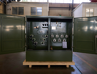
1250kVA Three Phase Pad Mounted Transformer
NPC ELECTRIC's 1250kVA Three Phase Pad Mounted Transformer is a high-performance, oil-immersed distribution transformer engineered for reliable underground power distribution in demanding environments. It delivers exceptional efficiency (up to 99.2% or higher), low no-load and load losses, and a 65°C average winding rise for extended service life exceeding 30-40 years. Key components include high-grade silicon steel core, aluminum or copper windings, 5-position tap changer (±2x2.5%), pressure relief valve, oil level gauge, and tamper-resistant enclosure in Munsell green finish.
170kV 4–40MVA Oil-Immersed High-Voltage Power Transformer
The 170kV 4–40MVA oil-immersed high-voltage power transformer is designed to support flexible capacity requirements across modern transmission and substation systems. Its wide MVA range allows a single platform to adapt to diverse grid configurations, from regional substations to industrial power interfaces. The transformer utilizes a refined oil-paper insulation system to ensure strong dielectric performance and long-term operational stability under high electrical stress. Advanced magnetic circuit optimization minimizes losses while maintaining excellent voltage regulation. The mechanical structure is engineered to withstand thermal cycling, short-circuit forces, and continuous operation under variable load conditions. With a focus on reliability, efficiency, and service life, this transformer is well suited for utility-scale projects that demand dependable high-voltage energy transfer with adaptable power ratings.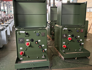
300kVA Single Phase Pad Mounted Transformer
300kVA Single Phase Pad Mounted Transformer is a compact and efficient solution tailored for underground residential distribution (URD) systems and loop-feed applications. This fully sealed, oil-immersed transformer features high-efficiency electrical steel cores and robust aluminum or copper windings to deliver minimal losses and superior voltage regulation from high-voltage inputs like 13.8kV or 34.5kV down to 120/240V or 277/480V secondary. The environmentally friendly PCB-free dielectric fluid ensures excellent cooling and insulation while meeting ANSI/IEEE standards for loop or radial feed configurations. Ideal for urban and suburban settings, this pad-mounted transformer provides quiet operation, high overload capacity.FAQ From Customers
-
What is a Transformer?A transformer is an electrical device used to change the voltage of alternating current (AC). It works on the principle of electromagnetic induction, converting high-voltage current into low-voltage current or low-voltage current into high-voltage current. Transformers are widely used in power transmission, distribution systems, and various electronic devices.
-
What are the main uses of a transformer?The main use of a transformer is voltage conversion. Transformers are used in power transmission systems to help transfer electricity from power plants to consumers. In addition, transformers are also used in electronic devices such as chargers, televisions, power adapters, etc., to adjust the voltage to meet the requirements of different devices.
-
Do you have UL listed?Yes, our transformer has UL listed. We have exported to America many pad mounted transformer,substation transformer and HV.
Welcome your inquiry
Honesty, Integrity, Frugality, Activeness and Passion