Distribution Transformer Specifications Explained: kVA, Voltage Ratings and Efficiency
2026-06-05
Distribution transformers are essential components in modern electrical systems, stepping down medium voltage to safe, usable levels for homes, businesses, and industries. Understanding key distribution transformer specifications — including kVA ratings, primary and secondary voltage ratings, and energy efficiency — is critical for engineers, contractors, and procurement teams. This comprehensive guide explains how to choose the right transformer based on power required, power factor, and real-world load conditions. Whether you need oil-immersed transformers, dry type distribution transformers, pole distribution transformers, or pad mount units, proper specification ensures optimal performance, lower power consumption, and long-term reliability in power distribution networks.
Distribution Transformers in Modern Power Systems
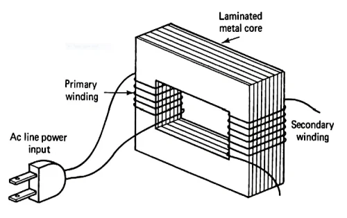
Distribution transformers play a critical role in electrical systems by stepping down medium voltage from the utility grid to safer, usable levels for end-users in residential, commercial, and industrial settings. Unlike power transformers that handle high-voltage transmission over long distances, distribution transformers focus on the final stage of power delivery, ensuring reliable voltage regulation close to the point of consumption. In practical engineering work, these units must operate continuously under varying loads while minimizing energy losses, maintaining safety, and complying with international efficiency standards.
From a field perspective, selecting and specifying a distribution transformer involves balancing load requirements, environmental conditions, installation constraints, and long-term operational costs. Engineers evaluate not only nameplate data but also real-world factors like ambient temperature, load profiles, and future expansion needs. This article explores key specifications—kVA ratings, voltage ratings, and efficiency—drawing from hands-on application in power distribution projects. It covers single-phase and three-phase designs, oil-immersed transformers, dry type distribution transformers, pole distribution transformers, and pad mount configurations to support informed decisions for global markets.
Understanding kVA Ratings: The Foundation of Transformer Capacity
The kVA (kilovolt-ampere) rating represents the apparent power capacity of a distribution transformer, indicating how much electrical load it can handle without exceeding the designed temperature rise limits. In real-world applications, kVA is not the same as kilowatts (kW); it accounts for both real power and reactive power, making it essential when dealing with inductive loads such as motors or lighting systems that have a power factor below 1.0.
To determine the required kVA from actual electrical systems' input voltage and power required, engineers start by calculating the total connected load in kW and then adjust for the power factor. The basic formula for three-phase transformers is:
kVA = (√3 × Voltage × Current) / 1000
For single-phase transformer applications:
kVA = (Voltage × Current) / 1000
In practice, add a 20-30% safety margin for future growth, motor starting inrush currents (which can reach 5-7 times full load), and diversity factors across multiple loads. For example, in a commercial building with 150 kW of mixed lighting and motor loads at a 0.85 power factor, the calculated apparent power might reach approximately 176 kVA. Selecting the next standard size—such as 200 kVA—prevents overload during peak demand while optimizing power consumption.
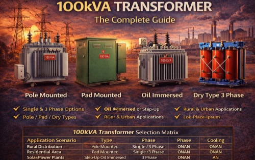
Standard kVA ratings for distribution transformers include 15, 25, 50, 75, 100, 167, 250, 500, 750, 1000, 1500, and 2500 kVA for three-phase units, with smaller increments for single-phase models. From an operational viewpoint, undersizing leads to overheating, insulation degradation, and reduced lifespan, while oversizing increases no-load losses and initial capital costs. In large-scale projects, utilities often model annual load profiles to match kVA precisely, ensuring the transformer operates near 50-70% average load for peak efficiency.
Power factor directly influences sizing: low power factor (common in industrial settings with inductive equipment) inflates apparent power, requiring larger kVA ratings or on-site correction capacitors. Engineers routinely perform load studies measuring voltage, current, and harmonics to refine these calculations before procurement.
Engineers reference these standard kVA ratings during sizing to match calculated apparent power while adding safety margins. The table below summarizes commonly available ratings for both single-phase and three-phase distribution transformers in real-world power distribution projects.
Common Standard kVA Ratings for Distribution Transformers
|
kVA Rating |
Single-Phase (Typical Applications) |
Three-Phase (Typical Applications) |
|
15kVA |
Residential lighting/small loads |
Small commercial |
|
25kVA |
Rural homes |
Light commercial |
|
50kVA |
Small farms |
Medium commercial |
|
75kVA |
- |
Small industrial |
|
100kVA |
- |
Commercial buildings |
|
167kVA |
Larger residential/pole-mounted |
- |
|
250kVA |
- |
Industrial feeders |
|
500kVA |
- |
Medium industrial/substation |
|
750-1000kVA |
- |
Large commercial/industrial |
|
1500-2500kVA |
- |
Heavy industrial/large-scale distribution |
Voltage Ratings: Primary and Secondary Considerations for Compatibility
Voltage ratings define the primary (input) and secondary (output) levels at which a distribution transformer is designed to operate safely and efficiently. Typical primary voltages for distribution applications range from 2.4 kV to 34.5 kV, while secondary voltages are commonly 120/240 V for single-phase residential service or 208Y/120 V, 480Y/277 V for three-phase commercial and industrial use.
In field installations, mismatched voltage can cause severe issues: overvoltage stresses insulation and increases core losses, while undervoltage leads to higher currents, overheating, and equipment malfunction downstream. When choosing a transformer, engineers verify the utility’s supply voltage, including allowable taps (usually ±2.5% or ±5% in 2-4 steps) to compensate for voltage drop along lines or varying load conditions.
For international export projects, compatibility with local grids is paramount. A common 11 kV/400 V or 33 kV/415 V configuration suits many regions, but North American markets often require 12.47 kV or 24.94 kV primaries with 480 V secondaries. Pad mount transformers in underground systems and pole distribution transformers in overhead networks must match these exactly to avoid costly rework.
Practical considerations include basic impulse level (BIL) for surge protection and impedance percentage (typically 4-7% for distribution units), which affects short-circuit currents and voltage regulation. High-impedance designs limit fault currents but may increase regulation drop under heavy loads. Engineers calculate voltage drop as:
% Voltage Drop ≈ (kVA × Impedance × 100) / (kVA Rating × Secondary Voltage Factor)
This analysis ensures stable power supplies to sensitive equipment like data centers or manufacturing lines.
In practice, voltage ratings must align precisely with the utility supply and downstream equipment. The following table outlines typical primary and secondary voltages encountered in international projects, highlighting differences between pole-mounted, pad-mounted, and dry-type configurations.
Typical Primary and Secondary Voltage Ratings for Distribution Transformers
|
Transformer Type |
Common Primary Voltage (kV) |
Common Secondary Voltage |
Typical Applications |
|
Pole Distribution |
11 / 12.47 / 13.8 / 33 |
120/240 V (Single-Phase) |
Overhead rural & residential lines |
|
Pad Mount |
11 / 12.47 / 24.94 / 34.5 |
208Y/120 V or 480Y/277 V |
Urban underground commercial |
|
Oil-Immersed |
2.4 – 34.5 |
400/230 V or 415/240 V |
Utility power distribution |
|
Dry Type |
6 – 15 (Medium Voltage) |
480 V or 600 V |
Indoor industrial & buildings |
|
3-Phase General |
11 / 22 / 33 |
400/230 V or 480 V |
Industrial & large commercial sites |
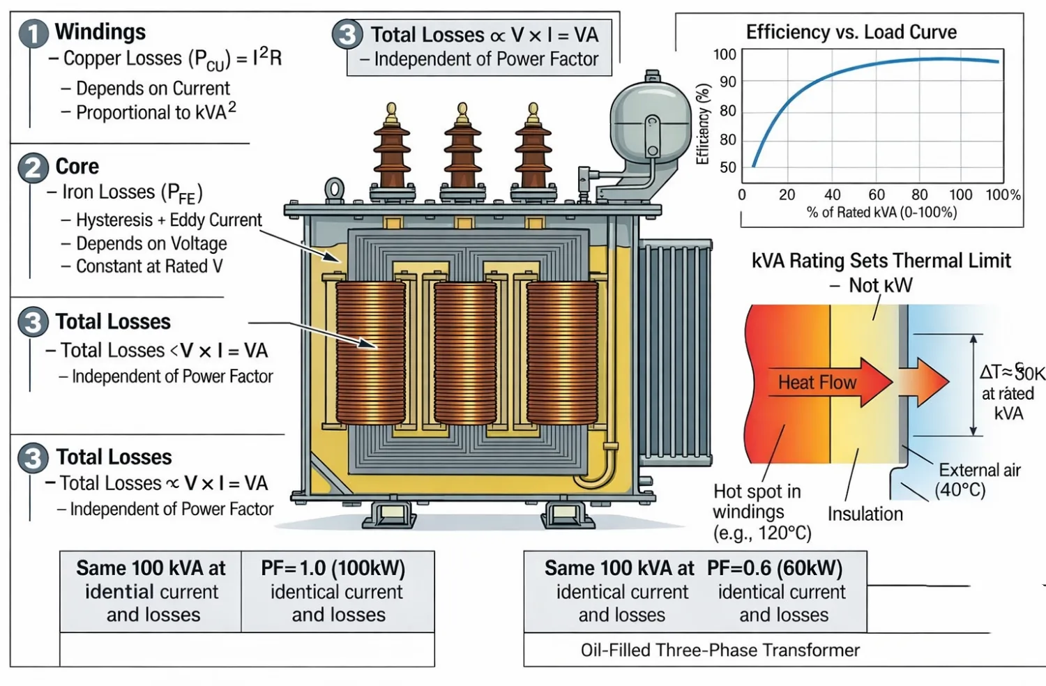
Efficiency in Distribution Transformers: Losses, Standards, and Real-World Impact
Efficiency measures how effectively a transformer converts input power to output power, expressed as a percentage: Efficiency = (Output Power / Input Power) × 100. Losses consist of no-load (core or iron) losses—constant regardless of load—and load (copper or winding) losses that vary with the square of the current.
Modern energy efficiency standards, such as those from the U.S. Department of Energy (DOE) and IEC 60076, drive designs toward lower losses. For liquid-immersed distribution transformers, efficiencies often exceed 99% at full load in higher ratings, while dry type distribution transformers prioritize fire safety but may show slightly higher losses due to air cooling limitations.
In operational practice, efficiency peaks at 35-50% load for many units, making accurate load forecasting vital. No-load losses dominate in lightly loaded rural feeders served by pole-mounted transformers, whereas copper losses prevail in heavily loaded urban pad mount installations. Energy-efficient designs use high-grade grain-oriented silicon steel cores or amorphous metal to reduce hysteresis and eddy currents.
From a total owning cost (TOC) perspective, engineers evaluate:
TOC = Initial Cost + (No-Load Loss Cost Factor × No-Load Losses) + (Load Loss Cost Factor × Load Losses)
Higher upfront costs for premium-efficiency transformers are often justified by reduced power consumption over 25-40 years of service life. In large-scale power distribution networks, even a 0.5% efficiency gain across hundreds of units translates to significant annual energy savings and lower carbon emissions.
Dry type distribution transformers excel in indoor or fire-sensitive environments (hospitals, schools) with cast resin insulation and forced-air cooling, offering lower maintenance but potentially higher initial investment. Oil-immersed transformers, using mineral oil or eco-friendly esters, provide superior cooling for outdoor pole or pad applications, supporting higher overload capacity and longer life in harsh climates.
From an operational perspective, the choice between oil-immersed and dry-type significantly impacts efficiency, maintenance schedules, and total owning cost. The table below provides a detailed comparison based on field experience in diverse electrical systems.
Comparison of Oil-Immersed vs. Dry-Type Distribution Transformers
|
Aspect |
Oil-Immersed Transformer |
Dry-Type Transformer |
|
Cooling Method |
Mineral oil or ester fluid (superior heat dissipation) |
Air (natural or forced) |
|
Typical Efficiency |
Higher (often >99% at rated load for larger kVA) |
Slightly lower due to air cooling limitations |
|
No-Load Losses |
Lower (0.2–0.3% of rated power) |
Higher (0.3–0.5% of rated power) |
|
Load Losses |
Lower under heavy load |
Higher (1.0–2.0% range) |
|
Fire & Environmental Safety |
Requires spill containment; oil leak risk |
Excellent (no oil, lower fire hazard) |
|
Maintenance |
Regular oil testing (DGA, moisture) |
Minimal (cleaning, connection checks) |
|
Installation |
Outdoor pole or pad mount preferred |
Ideal for indoor or fire-sensitive areas |
|
Typical kVA Range |
Up to 2500+ kVA |
Better suited for lower to medium kVA |
|
Lifespan & Overload |
Longer life with good cooling; higher overload capacity |
Good in controlled environments; may need derating |
Types of Distribution Transformers: Oil-Immersed vs. Dry Type and Installation Configurations
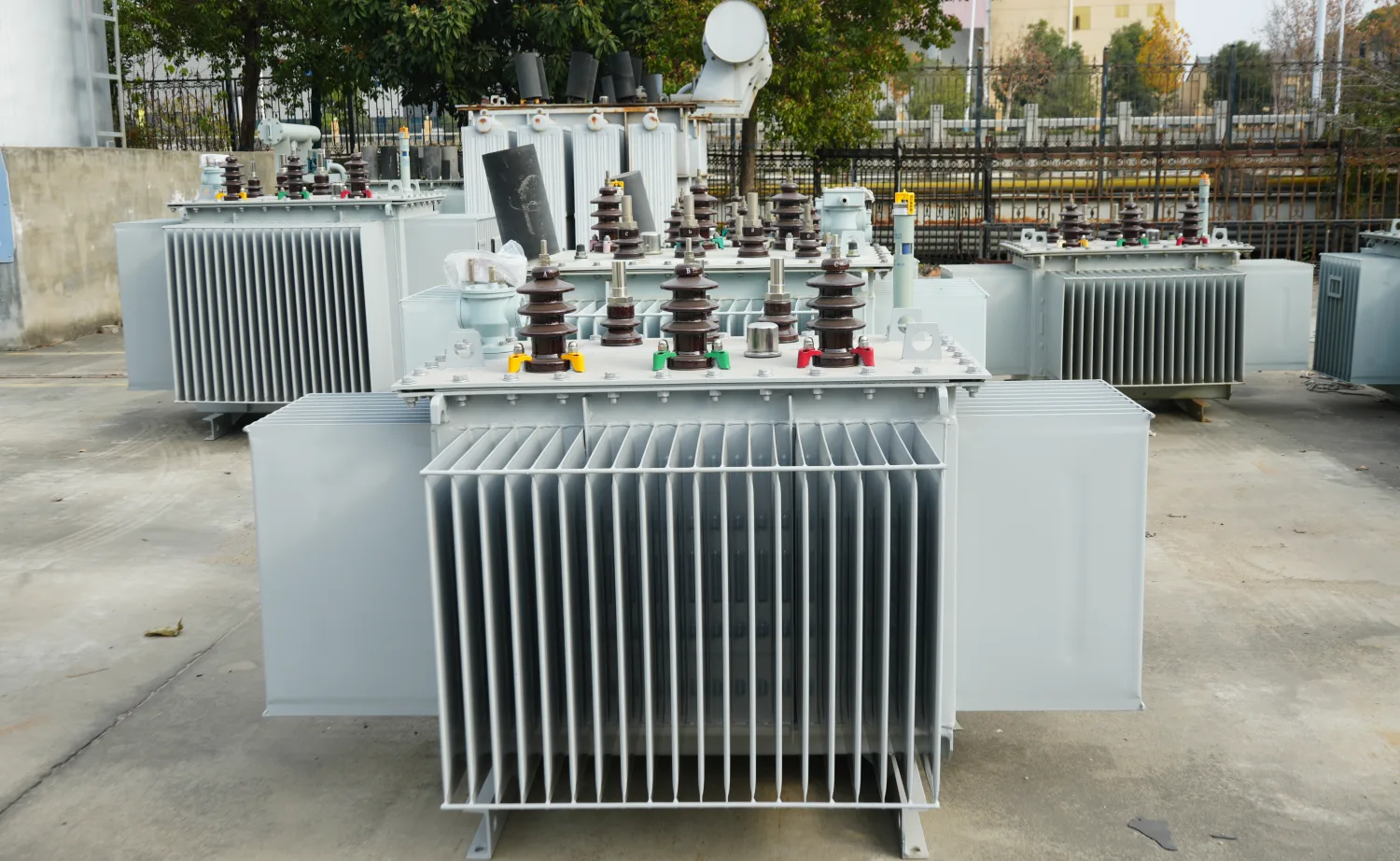
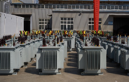
Oil-immersed transformers remain the workhorse for utility-scale power and distribution transformer applications due to excellent heat dissipation and cost-effectiveness at higher kVA levels. They suit pole distribution transformer setups in rural overhead lines and pad mount configurations in urban underground systems. Regular oil testing for dielectric strength, moisture, and dissolved gases is standard maintenance to prevent failures.
Dry type distribution transformers, cooled by air or fans, eliminate oil-related fire and spill risks, making them ideal for buildings and environmentally sensitive areas. They require minimal maintenance but may need derating in high-ambient temperatures or dusty conditions. Three-phase transformer designs dominate industrial feeds, while single-phase units serve residential loads efficiently.
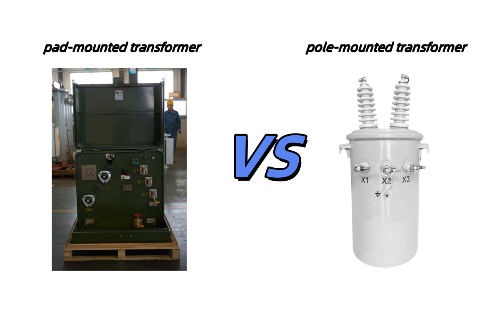
Pole-mounted units are compact, cost-effective for overhead lines, and easy to install on utility poles, but they expose components to weather. Pad-mounted transformers offer tamper-resistant enclosures at ground level, better aesthetics, and safer operation near public spaces. Selection depends on site surveys: overhead vs. underground infrastructure, space availability, and safety regulations.
Practical Guidelines for Selecting and Specifying Distribution Transformers
From an engineering workflow, begin with a detailed load study including maximum demand, power factor, harmonics (K-factor for non-linear loads), and growth projections. Match primary and secondary voltage to the electrical systems, then choose kVA based on calculated apparent power plus margin. Evaluate efficiency class against project lifecycle costs, considering local energy prices.
Consult reputable distribution transformer manufacturers for custom features like tap changers, monitoring sensors (temperature, oil level), or surge arresters. For international exports, ensure compliance with IEC, ANSI/IEEE, or regional standards, including testing for temperature rise, impedance, and dielectric withstand.
In summary, proper specification of kVA, voltage ratings, and efficiency ensures reliable, cost-effective performance in real power distribution networks. By prioritizing data-driven sizing and application-specific choices—whether oil-immersed, dry type, pole, or pad mount—engineers deliver robust solutions that minimize downtime, reduce energy waste, and support sustainable electrical infrastructure.
Related Articles

Related Products
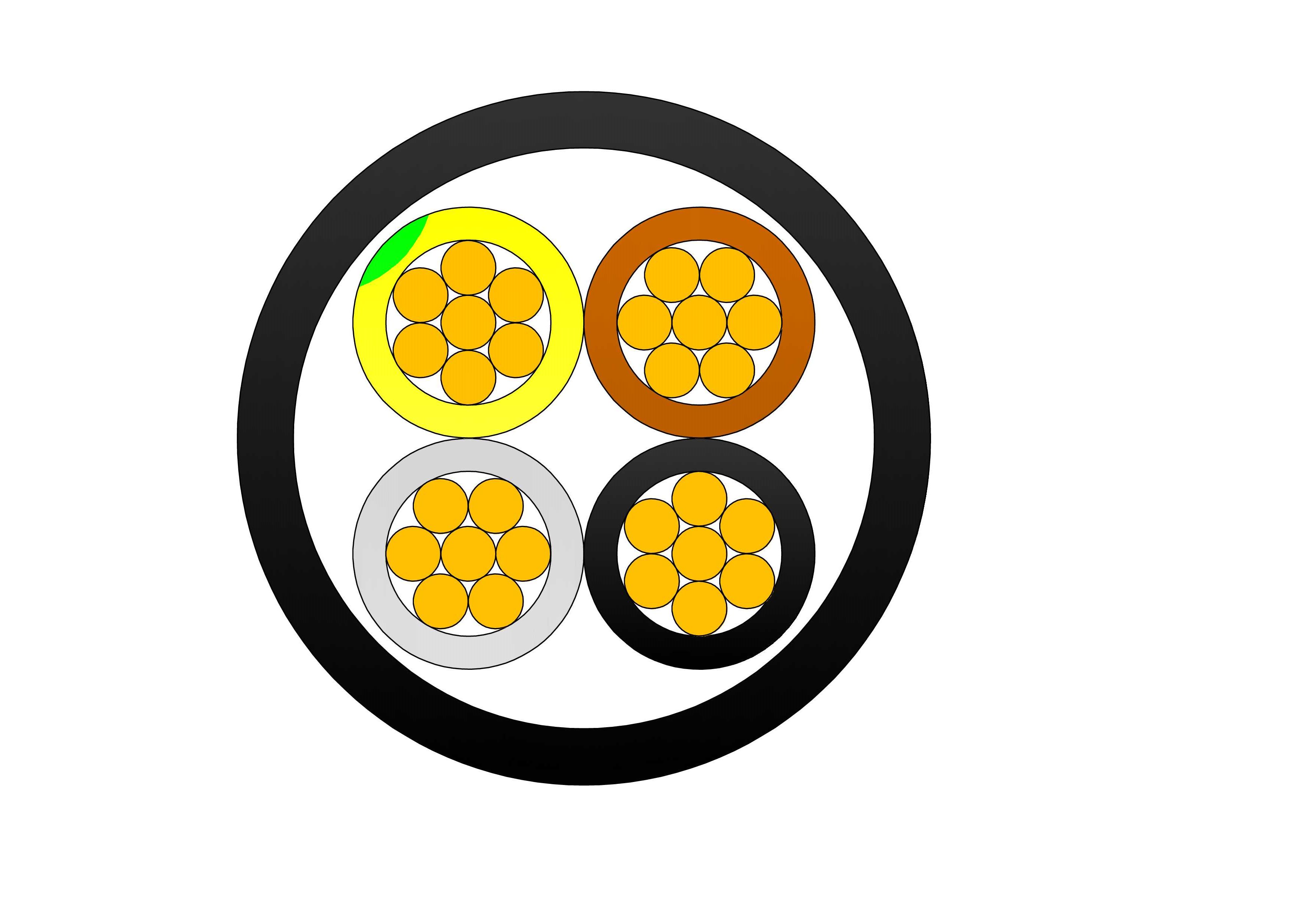
2/3/4 Cores Aluminum Cable AL/XLPE/PVC Low Voltage Power Cable
The 2/3/4 Cores Aluminum Cable AL/XLPE/PVC is designed for reliable low-voltage power transmission and distribution in industrial, commercial, and utility applications. Manufactured with high-conductivity stranded aluminum conductors, premium XLPE insulation, and a durable PVC outer sheath, the cable provides an economical alternative to copper cables while maintaining excellent electrical performance. The XLPE insulation offers outstanding dielectric strength, low insulation losses, and thermal stability, allowing continuous conductor operation at temperatures up to 90°C. The PVC sheath protects against moisture, abrasion, chemicals, UV exposure, and environmental stress, ensuring long-term durability in demanding installations. Available in 2-core, 3-core, and 4-core configurations, the cable is suitable for single-phase and three-phase power systems. Manufactured according to IEC 60502-1 standards, it ensures safe and efficient electrical distribution across a wide range of applications. Its lightweight construction reduces transportation and installation costs, making the 2/3/4 Cores Aluminum Cable AL/XLPE/PVC an ideal solution for power infrastructure, commercial facilities, industrial plants, and renewable energy projects.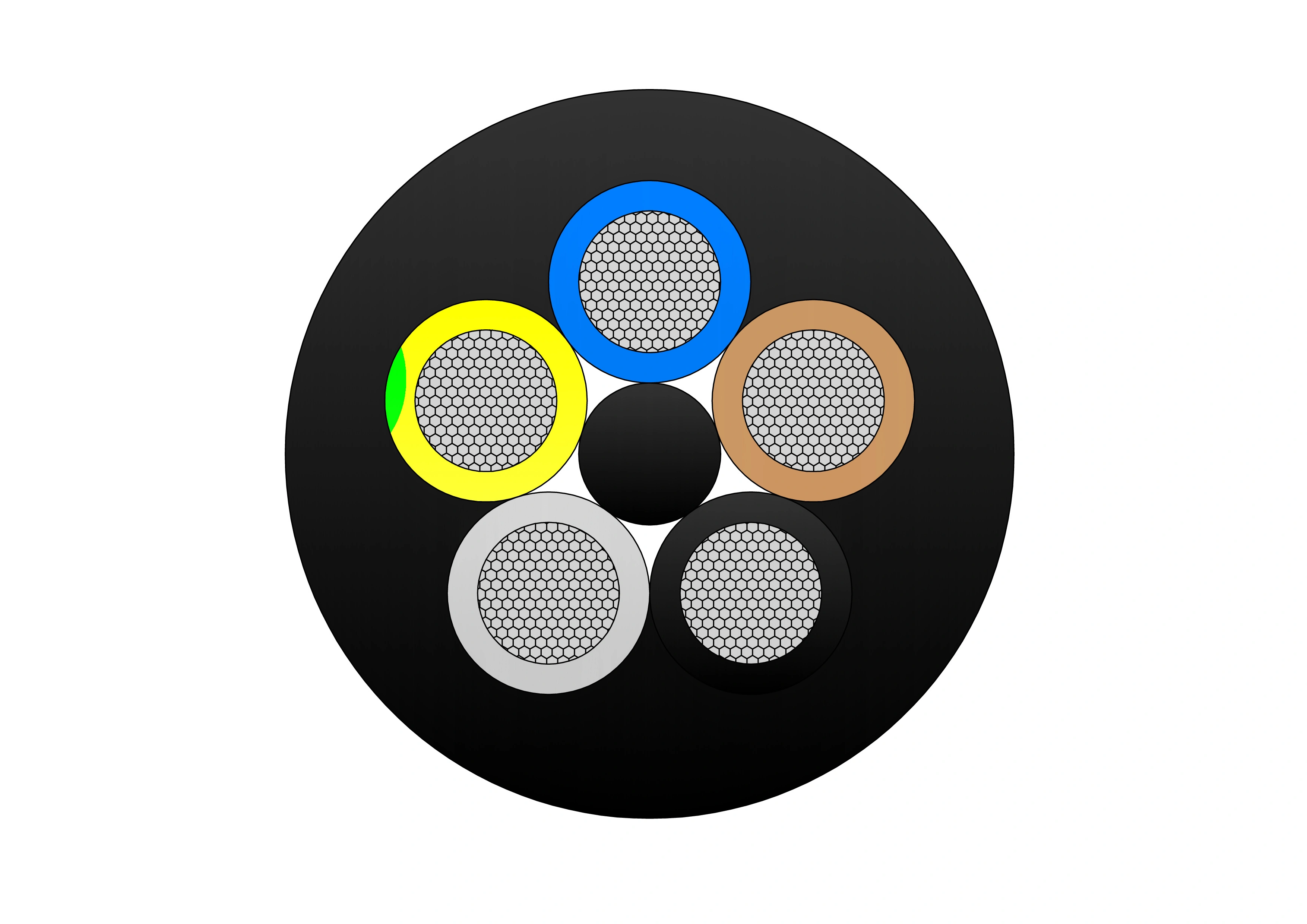
(N)TSCGECECWOU 8.7/15kV and 12/20kV ZH Cable
The (N)TSCGECECWOU 8.7/15kV and 12/20kV ZH cable is a flexible medium voltage power cable designed and manufactured to DIN VDE 0250 standards. Engineered for demanding mining, tunneling, and mobile equipment applications, it features EPR insulation, a halogen-free flame-retardant sheath, and a concentric copper conductor to ensure exceptional mechanical strength, EMC protection, and resistance to oil, moisture, and fire. With a robust PUR outer sheath and halogen-free materials, this cable provides high flexibility and durability for reeling and trailing systems in harsh industrial environments, making it ideal for tunnel boring machines, mining conveyors, and other heavy-duty energy supply applications.
500kVA Dry Type Transformer
NPC ELECTRIC 500kVA Dry-Type Transformer offers reliable and efficient power distribution with a compact, oil-free design. It ensures safe, low-maintenance operation with advanced insulation and cooling systems, making it ideal for industrial and commercial use. With a capacity of 500kVA, it delivers stable performance while being environmentally friendly and cost-effective. Key characteristics feature three-phase design (single-phase adaptable), primary voltages 208V–600V (e.g., 480V Delta, 600V Delta), secondary voltages such as 208Y/120V, 480Y/277V, or custom, aluminum or copper windings, 150°C rise (standard) or 115°C/80°C with 220°C insulation class, ±2×2.5% primary taps, NEMA 1 ventilated enclosure (NEMA 3R/encapsulated options), natural convection cooling (AN), electrostatic shielding, and low sound levels per NEMA.
Type 245 Flexible Rubber Mining Cable
The Type 245 Flexible Rubber Mining Cable is an extra-heavy-duty flexible cable purpose-built for the most severe high-voltage underground mining environments. It features finely stranded tinned copper conductors (class 5) for exceptional flexibility and corrosion resistance, EPR (ethylene propylene rubber) insulation for outstanding dielectric strength, thermal stability (90°C continuous rating), and resistance to moisture/heat, an overall tinned copper braid screen providing superior EMI protection and grounding, and an extra-heavy-duty flame-retardant rubber outer sheath engineered to endure extreme abrasion, crushing, impact, cutting, tearing, oils, chemicals, and repeated high-tension reeling/drag. Compliant with AS/NZS 2802 and rigorous mining safety standards, it supports very high tensile loads, frequent flexing, tight bending radii, and reliable operation in wet, dusty, and hazardous mine conditions. The Type 245 is specifically suited for high-power trailing applications in coal and metalliferous mines, powering longwall shearers, continuous miners, face conveyors, shuttle cars, and other critical high-capacity mobile equipment, delivering maximum safety, durability, and uptime.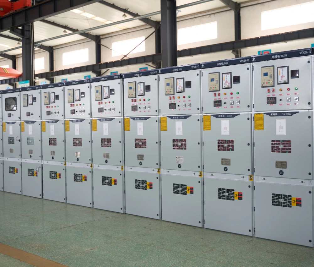
Medium Voltage Switchgear
The Medium Voltage Switchgear is an advanced electrical distribution and protection system engineered for safe, reliable, and efficient medium-voltage power management in utility substations, industrial facilities, renewable energy plants, commercial infrastructure, and smart-grid applications. The system integrates vacuum circuit breakers, disconnect switches, protection relays, busbar assemblies, intelligent monitoring systems, and automation devices into a compact modular enclosure structure to ensure stable electrical distribution and enhanced operational safety. Designed with high-strength insulated structures and precision-manufactured electrical components, the medium voltage switchgear provides outstanding dielectric performance, thermal stability, and mechanical durability under demanding operating conditions. Its modular cabinet configuration improves installation flexibility, simplifies maintenance procedures, and supports future power distribution expansion while minimizing operational downtime and maintenance costs. The Medium Voltage Switchgear supports air-insulated and gas-insulated configurations, intelligent automation systems, remote communication protocols, and smart-grid integration technologies. With customizable protection schemes and scalable electrical distribution capabilities, the switchgear delivers dependable medium-voltage control and protection performance for industrial automation systems, utility power networks, renewable energy integration projects, transportation infrastructure, and mission-critical electrical facilities.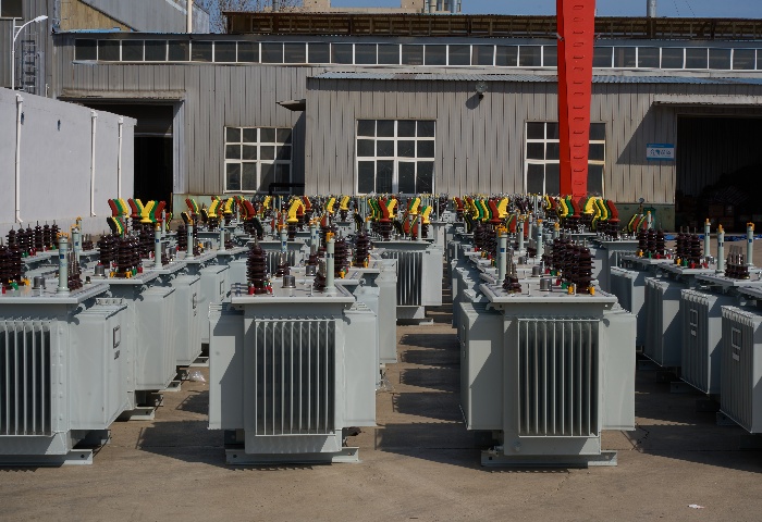
200kVA Oil Immersed Transformer
The 200kVA oil-immersed transformer produced by our company adopts a new insulation structure to improve the short-circuit resistance; the iron core is made of high-quality cold-rolled silicon steel sheet; the high-voltage winding is made of high-quality oxygen-free copper wire and adopts a multi-layer cylindrical structure; all fasteners are treated with special anti-loosening treatment. Standard configuration includes mineral oil or FR3 natural ester fluid, ONAN cooling, aluminum or copper windings, high-voltage 34.5kV / 24.94kV / 13.8kV / 12.47kV / 4.16kV.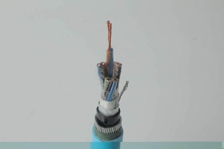
Instrumentation Cables—PVC Insulated,Individual & Overall Screened, Unarmoured PVC Sheathed Cables(CU/PVC/OSCR/PVC)
Instrumentation Cables are multi-conductor cables that carry and transport low-voltage electrical signals. These low-voltage signals are used to control and monitor electrical power systems. Instrumentation cables have many different industrial applications that include broadcasting, equipment control, such as drilling and pumping in the oil and gas industry, and data transfer, which includes analog and digital signals. They are manufactured according to the BS EN 50288-7 and BS EN 50288-1 standards to ensure quality. Instrumentation cables come in twisted pairs, triads, and quads, depending on the customer’s applications; twisting reduces any electromagnetic interference by reducing the chances of electrical voltages and currents being induced in the conductor. Individual and overall screening are also applied in instrumentation cables to optimize the signal transferred and further reduce any electromagnetic interference. Screening of pairs, triads, or quads also includes a drain wire earthed to the ground, which ensures a noise-free signal transmission.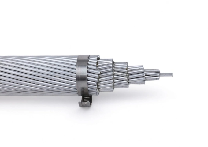
1/0 AWG Poppy AAC Cable
The 1/0 AWG Poppy AAC Cable represents premium All Aluminum Conductor technology for overhead power applications. Manufactured with seven strands of high-conductivity 1350-H19 aluminum, this bare conductor delivers an optimal balance of electrical efficiency and mechanical performance. Its 0.368-inch diameter and 1,990 lbs breaking strength support reliable operation with 247 amps capacity and minimal sag. Weighing just 99.1 lbs per 1000 ft, the Poppy AAC reduces structural loading and installation expenses while providing excellent corrosion resistance for extended outdoor service. Compliant with ASTM B-230 and B-231, the 1/0 AWG Poppy AAC Cable offers low DC resistance of 0.164 ohms/1000 ft at 20°C. It undergoes stringent quality testing from raw materials through finished product, making it an ideal choice for new builds and upgrades in transmission and distribution systems requiring dependable, lightweight bare conductors.
3/0 Aega Aluminum Conductor Triplex Overhead Service Drop Cable
The 3/0 Aega Aluminum Conductor Triplex Overhead Service Drop Cable is designed to deliver safe and efficient overhead power distribution for utility networks. It features two insulated aluminum phase conductors helically wrapped around a bare aluminum neutral messenger, providing strong mechanical support and stable electrical performance. Manufactured using premium aluminum materials and high-performance insulation compounds, the 3/0 Aega Aluminum Conductor Triplex Overhead Service Drop Cable offers excellent resistance to corrosion, UV radiation, and environmental stress. Its optimized construction supports easy handling and installation while meeting utility and industry standards. The cable performs reliably under mechanical load, temperature variation, and long-term outdoor exposure. Strict quality management systems and detailed testing procedures are implemented throughout production to ensure consistent performance and dependable service life.
6 Hippa Aluminum Conductor Triplex Overhead Service Drop Cable Wire
6 Hippa Aluminum Conductor Triplex Overhead Service Drop Cable Wire is engineered for safe and efficient overhead service drop connections. It features two insulated aluminum conductors stranded around a reinforced neutral messenger, providing balanced electrical performance and mechanical stability. This cable offers excellent corrosion resistance, low sag characteristics, and simplified installation. The insulation system of the 6 Hippa Aluminum Conductor Triplex Overhead Service Drop Cable Wire is designed to withstand prolonged exposure to sunlight, moisture, and temperature variations, ensuring reliable outdoor operation. A complete quality assurance program is implemented during manufacturing, covering raw material testing, process inspection, and finished product testing. Each production stage follows standardized procedures to ensure conformity with international standards and utility requirements. The 6 Hippa Aluminum Conductor Triplex Overhead Service Drop Cable Wire is a dependable choice for modern overhead power distribution systems.
N2XS2Y Medium Voltage Power Cable(6/10kV, 12/20kV, 18/30kV)
N2XS2Y Medium Voltage Power Cable (6/10kV, 12/20kV, 18/30kV) is engineered for reliable medium voltage power transmission and distribution. Featuring stranded copper conductors, cross-linked polyethylene (XLPE) insulation, copper tape or wire screen, and robust polyethylene (PE) outer sheath, it fully complies with IEC 60502-2 standards. The PE sheath provides excellent resistance to moisture, UV, chemicals, and mechanical stress, ideal for direct burial. With low dielectric losses, high thermal stability, and superior partial discharge performance, it ensures efficient operation and long service life. Longitudinal and radial water blocking options available for enhanced protection. Flame-retardant and environmentally durable, the N2XS2Y Medium Voltage Power Cable is the preferred choice for utilities, industrial plants, renewable energy projects, and infrastructure networks requiring safe, high-performance medium voltage cabling in harsh underground or outdoor conditions worldwide.
35kV Oil Immersed Transformer
NPC ELECTRIC's 35kV Oil Immersed Transformer is a premium three-phase power transformer optimized for high-voltage step-down in 50/60Hz AC systems with primary ratings of 35kV (or 33-38.5kV range). It incorporates a robust conservator or fully sealed tank design with efficient radiator cooling (ONAN standard, ONAF optional), ensuring exceptional thermal dissipation, moisture exclusion. Outdoor-rated with pollution-resistant bushings (BIL 170-200kV), Dyn11/Ynd1 vector groups, and low noise (<62dB), it provides stable 35kV to secondary voltages (e.g., 10kV/6.3kV/0.4kV) conversion, enhancing grid stability, minimizing transmission losses, and supporting demanding applications in harsh or high-altitude conditions.
300kVA Single Phase Pad Mounted Transformer
300kVA Single Phase Pad Mounted Transformer is a compact and efficient solution tailored for underground residential distribution (URD) systems and loop-feed applications. This fully sealed, oil-immersed transformer features high-efficiency electrical steel cores and robust aluminum or copper windings to deliver minimal losses and superior voltage regulation from high-voltage inputs like 13.8kV or 34.5kV down to 120/240V or 277/480V secondary. The environmentally friendly PCB-free dielectric fluid ensures excellent cooling and insulation while meeting ANSI/IEEE standards for loop or radial feed configurations. Ideal for urban and suburban settings, this pad-mounted transformer provides quiet operation, high overload capacity.
2 Conch Aluminum Conductor Triplex Overhead Service Drop Cable
The 2-2-2 Conch Aluminum Conductor Triplex Overhead Service Drop Cable is a trusted solution for overhead power distribution from utility poles to residential or commercial weatherheads. Featuring concentric-lay-stranded 1350-H19 aluminum phase conductors (#2 AWG, 7-strand), durable black cross-linked polyethylene (XLPE) insulation, and a bare ACSR neutral messenger (#2 AWG, 6/1), it provides excellent electrical conductivity, superior weather/UV resistance, and mechanical support. Rated for 600 volts phase-to-phase with conductor temperatures up to 90°C (XLPE), it delivers an allowable ampacity of approximately 150 amps. Compliant with ASTM B-230, B-231, B-232, B-399, and ICEA S-76-474 standards, this lightweight, flexible cable ensures easy installation and long-term reliability in harsh outdoor environments, including wind, ice loading, and temperature fluctuations.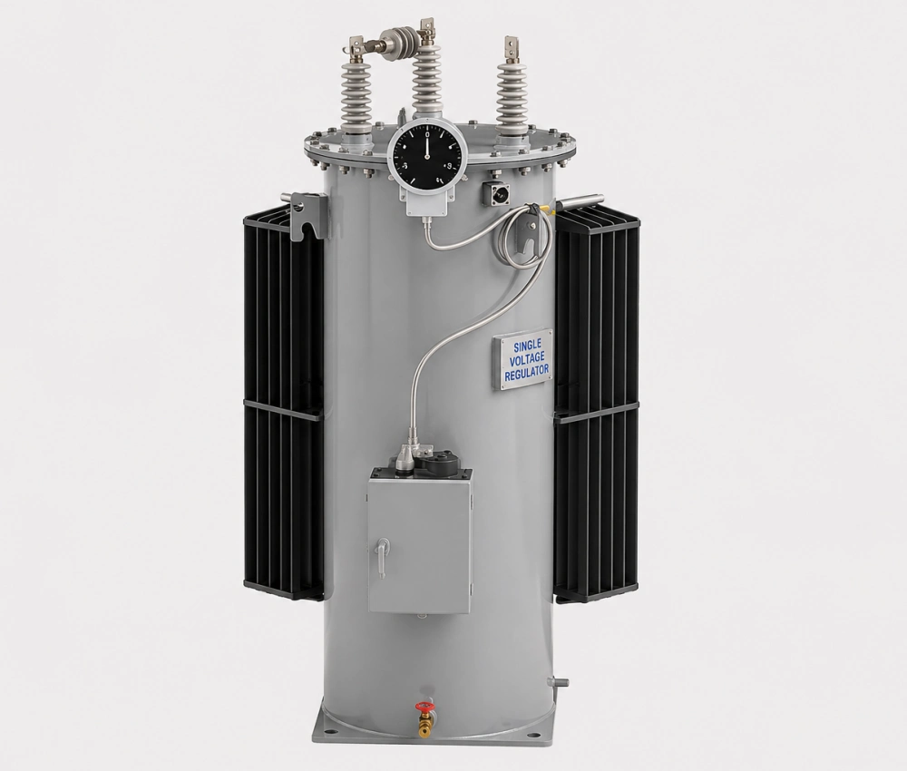
Single Phase Automatic Step Voltage Regulator
The Single-phase Automatic Step Voltage Regulator is an advanced, intelligent voltage stabilization device designed to automatically correct voltage fluctuations and deliver stable output for sensitive electrical equipment. Utilizing a high-efficiency toroidal or laminated core with premium copper windings and multiple tap positions, this regulator provides fast, precise step-type voltage correction (±10% to ±30% input range) with response times under 1 second. It features a microprocessor-based digital controller with LCD display, multiple protection functions (over-voltage, under-voltage, overload, short-circuit, and surge), and automatic bypass capability. Built with robust construction and high overload capacity (up to 200% for short durations), it ensures reliable performance in varying load conditions while maintaining low waveform distortion and high efficiency (>98%). Ideal for single-phase 220V/230V/240V systems, this voltage regulator is widely used in residential, commercial, and light industrial applications to protect equipment from unstable grid voltage and extend service life.Welcome your inquiry
Honesty, Integrity, Frugality, Activeness and Passion