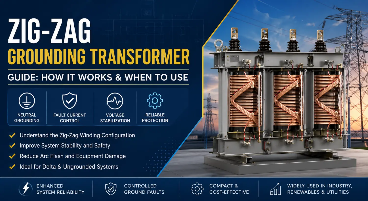
Zig-Zag Grounding Transformer Guide: How It Works & When to Use
2026-07-01
In modern industrial and utility electrical networks, grounding strategy is one of the most critical aspects of power system reliability and protection. Facilities operating medium-voltage or ungrounded distribution systems often face challenges related to transient overvoltages, unstable phase voltages, arc flash hazards, and difficult fault detection during line-to-ground fault conditions.
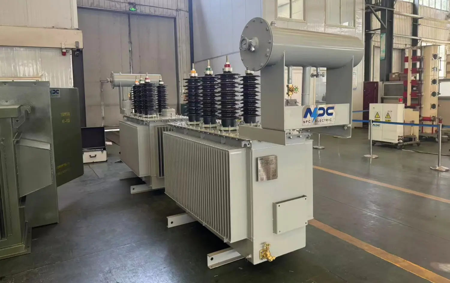
A Zig-Zag Grounding Transformer is specifically designed to solve these issues by creating an artificial neutral point for systems that otherwise lack a neutral connection. Unlike conventional power transformers used for voltage transformation, zig zag grounding transformers primarily serve grounding and fault-current management functions.
Today, zig-zag transformer grounding solutions are widely used in renewable energy plants, industrial manufacturing facilities, petrochemical systems, mining operations, data centers, and utility substations. Their ability to stabilize phase voltages, improve protection coordination, and support neutral grounding makes them essential in many modern power system designs.
1. What Is a Zig-Zag Grounding Transformer?
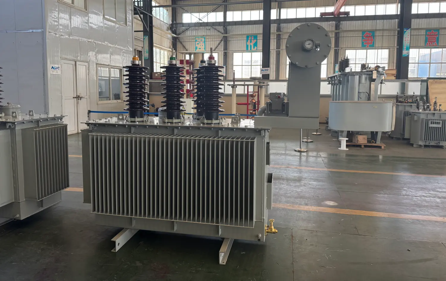
A zig-zag transformer is a special type of earthing transformer designed to provide a neutral grounding point in three-phase electrical systems. It is most commonly installed in delta-connected or ungrounded systems where no natural neutral exists.
Unlike a standard wye-delta transformer used for voltage conversion between systems, the zig-zag grounding transformer typically does not transfer significant real power between primary and secondary windings. Instead, its primary role is to:
- Establish a neutral connection
- Provide controlled ground fault current paths
- Stabilize system voltages
- Reduce transient overvoltages
- Improve the protection relay operation
The name “zig-zag” comes from its unique winding configuration. Each transformer limb contains two winding sections connected to different phases in opposite directions. Under balanced operating conditions, the magnetic flux cancels internally, resulting in very low impedance to zero-sequence currents while maintaining high impedance to balanced three-phase currents.
This unique transformer design allows grounding transformers to connect efficiently to systems without significantly affecting normal load operation.
2. How the Zig-Zag Winding Configuration Works
The operating principle of a Zig-Zag Grounding Transformer depends on its specialized winding arrangement.
Basic Winding Structure
Each core leg contains two equal windings:
- One winding connected to one phase
- Another winding is connected to a different phase with opposite polarity
This zig-zag connection creates phase displacement that cancels balanced system currents while permitting zero-sequence fault currents to flow.
Under normal operating conditions:
- Three-phase currents remain balanced
- Net magnetic flux is nearly zero
- Minimal transformer current flows
However, during a line to ground fault:
- Zero-sequence current appears
- The transformer provides a return path through the neutral grounding point
- Protection devices can detect and isolate the fault rapidly
The design effectively creates an artificial neutral without requiring a full wye-delta connection transformer arrangement.
Voltage Stabilization
One major advantage of zig-zag grounding transformers is the stabilization of phase voltages during abnormal conditions.
In ungrounded systems, a single ground fault may cause the unfaulted phases to rise toward line-to-line voltage levels, stressing insulation and increasing failure risk.
The zig-zag transformer limits this instability by referencing the system to ground through the neutral connection.
This improves:
- Equipment insulation life
- Relay sensitivity
- Surge suppression
- System safety
3. Why Neutral Grounding Matters in a Power System
Neutral grounding is fundamental to electrical safety and system stability. Without proper grounding, even a minor insulation failure can escalate into catastrophic equipment damage.
Problems in Ungrounded Systems
Ungrounded systems were historically popular because they allowed continued operation during a first ground fault. However, modern industrial systems increasingly avoid completely ungrounded operation because of several disadvantages:
Transient Overvoltage
Arcing ground faults can create dangerous switching surges several times above rated voltage.
Difficult Fault Detection
Fault current may be too small for protective relays to identify quickly.
Insulation Stress
Unbalanced phase voltages accelerate the aging of cables, motors, and switchgear.
Increased Arc Flash Risk
Sustained faults can evolve into severe arc flash events.
For these reasons, many facilities replace ungrounded systems with controlled neutral grounding using zig-zag transformer grounding systems.
4. Types of Neutral Grounding Used with Zig-Zag Transformers
The grounding method selected depends on the power system design, fault current requirements, and operational philosophy.
Solid Grounding
In solid grounding systems, the transformer neutral is directly connected to earth.
Advantages include:
- Fast fault clearing
- Simple protection schemes
- Stable phase voltages
However, fault currents can become very high, increasing thermal and mechanical stress on equipment.
Solid grounding is more common in low-voltage systems than medium-voltage industrial networks.
Resistance Grounding
Resistance grounding is the most common configuration used with zig-zag grounding transformers.
A grounding resistor is connected between the transformer neutral and earth to limit fault current.
Benefits include:
- Reduced arc flash energy
- Lower equipment damage
- Controlled fault current magnitude
- Improved continuity of operation
Resistance grounding systems are widely used in:
- Mining facilities
- Petrochemical plants
- Paper mills
- Data centers
- Renewable energy systems
Engineers often classify resistance grounding into:
Low Resistance Grounding (LRG)
Typically allows 50–1000 A of fault current for rapid fault clearing.
High Resistance Grounding (HRG)
Limits fault current to very low levels, often below 10 A, allowing temporary operation during the first faults.
Table: Comparison of Neutral Grounding Methods in Industrial Power Systems
|
Grounding Method |
Fault Current Level |
System Stability |
Arc Flash Risk |
Typical Applications |
Main Advantage |
Main Limitation |
|
Solid Grounding |
Very High |
Excellent |
High |
Low-voltage commercial systems |
Fast fault clearing |
High equipment stress |
|
Resistance Grounding |
Medium or Low |
Excellent |
Reduced |
Industrial MV systems |
Controlled fault energy |
Requires a grounding resistor |
|
Ungrounded Systems |
Very Low |
Poor during faults |
Moderate |
Legacy industrial systems |
Continued operation after the first fault |
Difficult fault detection |
|
Zig-Zag Grounding Transformer |
Adjustable |
Excellent |
Reduced |
Delta systems, renewable energy plants |
Creates a neutral point economically |
Requires proper protection coordination |
|
Wye Delta Transformer Grounding |
Medium |
Good |
Moderate |
Utility substations |
Combines grounding and voltage transformation |
Larger size and higher cost |
5. Applications of Zig-Zag Grounding Transformers
Zig-zag grounding transformers are used wherever systems require a neutral point but lack one inherently.
Renewable Energy Plants
Solar and wind power systems frequently use inverter-based delta outputs. A zig-zag transformer establishes grounding reference points and improves protection coordination.
This is especially important in utility-scale solar farms where transient behavior from power electronics can create grounding challenges.
Table: Typical Industries and Use Cases for Zig-Zag Grounding Transformers
|
Industry |
Typical Voltage Level |
Why Zig-Zag Grounding Is Used |
Common Grounding Type |
|
Solar Power Plants |
11kV – 35kV |
Stabilize the inverter output and provide neutral grounding |
Resistance Grounding |
|
Wind Farms |
13.8kV – 34.5kV |
Control transient overvoltages |
Resistance Grounding |
|
Mining Operations |
4.16kV – 15kV |
Improve personnel safety and reduce arc flash risk |
High Resistance Grounding |
|
Petrochemical Plants |
6.6kV – 13.8kV |
Maintain system reliability during faults |
Low Resistance Grounding |
|
Data Centers |
480V – 15kV |
Improve grounding stability for sensitive equipment |
Solid or Resistance Grounding |
|
Utility Substations |
11kV – 33kV |
Create neutral points in delta systems |
Solid Grounding |
|
Manufacturing Facilities |
4.16kV – 13.8kV |
Improve protection coordination |
Resistance Grounding |
Industrial Manufacturing
Factories operating medium-voltage motor systems commonly use delta-connected distribution networks.
Applications include:
- Steel plants
- Cement facilities
- Chemical processing
- Automotive manufacturing
The earthing transformer improves system stability while supporting selective protection coordination.
Utility Substations
Utilities install zig-zag grounding transformers to:
- Ground tertiary systems
- Stabilize substation auxiliary networks
- Control zero-sequence currents
These transformers are particularly useful where adding a full wye-delta transformer would be economically impractical.
Data Centers
Modern data centers demand high reliability and controlled fault management.
Zig-zag grounding systems help:
- Reduce transient disturbances
- Improve UPS coordination
- Enhance equipment protection
- Support continuous operation
6. Advantages of Zig-Zag Grounding Transformers
The growing use of zig-zag transformer technology is driven by several important operational advantages.
Compact Transformer Design
Compared with conventional grounding transformer alternatives, zig-zag units use less copper and core material, reducing size and cost.
Effective Fault Current Control
By combining the transformer with resistance grounding, engineers can precisely manage the line-to-ground fault current magnitude.
This improves protection selectivity while minimizing damage.
Improved System Stability
The transformer stabilizes phase voltages and suppresses transient overvoltages during abnormal conditions.
This increases overall power system reliability.
Flexible Installation
Zig-zag grounding transformers can be retrofitted into existing systems without major redesign.
This is especially valuable for industrial facilities upgrading aging electrical infrastructure.
Lower Equipment Stress
Controlled neutral grounding reduces:
- Mechanical stress
- Thermal stress
- Insulation degradation
- Arc flash severity
This extends equipment life and reduces maintenance costs.
7. Design Considerations for Zig-Zag Grounding Systems
Table: Key Engineering Parameters for Zig-Zag Grounding Transformer Design
|
Parameter |
Typical Range |
Engineering Importance |
|
System Voltage |
4.16kV – 35kV |
Determines insulation class and BIL rating |
|
Ground Fault Current |
5A – 1000A |
Defines thermal and mechanical withstand capability |
|
Fault Duration |
10s – 60s |
Impacts conductor and winding sizing |
|
Grounding Resistor Value |
Application-specific |
Controls fault current magnitude |
|
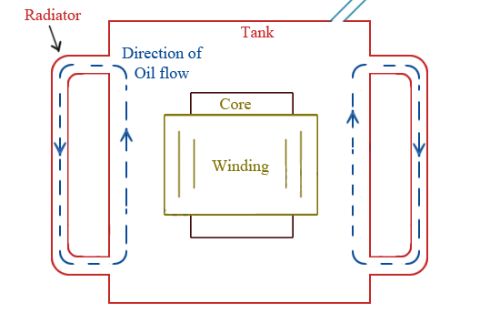
Cooling Method |
ONAN / Dry Type |
Affects installation environment suitability |
|
Insulation Class |
Class F / H |
Influences thermal aging performance |
|
Frequency |
50Hz / 60Hz |
Determines magnetic design |
|
Harmonic Tolerance |
Low to High |
Important for renewable energy and VFD systems |
|
Protection Relay Coordination |
Required |
Ensures selective fault isolation |
|
Indoor / Outdoor Installation |
Both |
Determines enclosure and IP protection rating |
Selecting the correct grounding transformer requires careful engineering analysis.
System Voltage
Transformer insulation levels must match system operating voltage and surge requirements.
Typical industrial ratings include:
- 4.16 kV
- 6.6 kV
- 11 kV
- 13.8 kV
- 33 kV
Fault Current Rating
The transformer must withstand the anticipated ground fault current magnitude and duration.
Common fault duration ratings include:
- 10 seconds
- 30 seconds
- 60 seconds
Grounding Resistor Selection
For resistance grounding systems, engineers must determine:
- Maximum permissible fault current
- Relay sensitivity
- Thermal capacity
- Arc flash objectives
Typical Ground Fault Current Levels for Different Grounding Methods
|
Grounding Method |
Typical Fault Current |
Fault Detection Speed |
Equipment Damage Risk |
Operational Continuity |
|
Solid Grounding |
1000A – 20kA |
Very Fast |
High |
Low |
|
Low Resistance Grounding |
50A – 1000A |
Fast |
Moderate |
Moderate |
|
High Resistance Grounding |
5A – 10A |
Slower |
Low |
High |
|
Ungrounded System |
< 5A |
Difficult |
High due to transient overvoltage |
High initially |
|
Zig-Zag with Resistance Grounding |
Adjustable |
Optimized |
Low |
High |
Harmonic Performance
Modern inverter-driven systems may generate harmonics that influence transformer heating and neutral current behavior.
Proper transformer design must account for these conditions.
Environmental Conditions
Outdoor substations require consideration of:
- Ambient temperature
- Humidity
- Pollution level
- Altitude
- Corrosion resistance
Oil-immersed and dry-type designs are both common, depending on installation requirements.
8. Zig-Zag Transformer vs Wye Delta Transformer
Although both transformers may participate in grounding strategies, their purposes differ substantially.
|
Feature |
Zig-Zag Grounding Transformer |
Wye Delta Transformer |
|
Primary Function |
Neutral grounding |
Voltage transformation |
|
Neutral Creation |
Yes |
Yes |
|
Power Transfer |
Minimal |
Significant |
|
Fault Current Path |
Excellent |
Moderate |
|
Space Efficiency |
Compact |
Larger |
|
Cost |
Lower |
Higher |
|
Grounding Performance |
Specialized |
General-purpose |
A wye-delta connection transformer is primarily intended for power conversion, while zig-zag grounding transformers are optimized specifically for neutral grounding and fault management.
How to Choose the Right Grounding Method for Your Power System
|
System Condition |
Recommended Solution |
|
Delta system without neutral |
Zig-Zag Grounding Transformer |
|
Need voltage transformation + grounding |
Wye Delta Transformer |
|
High arc flash concern |
High Resistance Grounding |
|
Utility distribution network |
Solid Grounding |
|
Renewable energy inverter system |
Zig-Zag with Resistance Grounding |
|
Need continuous operation during the first fault |
High Resistance Grounding |
|
Sensitive electronic equipment installed |
Controlled Neutral Grounding |
9. Common Mistakes When Using Zig-Zag Grounding Transformers
Improper grounding design can compromise safety and reliability.
Undersized Fault Rating
Selecting a transformer without sufficient thermal withstand capability can lead to catastrophic failure during faults.
Incorrect Resistor Sizing
Excessively low resistance increases fault energy, while excessively high resistance may prevent relay operation.
Ignoring Harmonics
Modern variable-frequency drives and renewable energy systems can introduce harmonic currents affecting transformer performance.
Table: Common Failure Modes and Causes in Zig-Zag Grounding Transformers
|
Failure Mode |
Primary Cause |
Potential Consequence |
Preventive Measure |
|
Winding Overheating |
Excessive fault duration |
Insulation damage |
Proper thermal sizing |
|
Neutral Resistor Failure |
Overcurrent stress |
Loss of grounding protection |
Routine resistor inspection |
|
Core Saturation |
Harmonic distortion |
Excessive heating |
Harmonic analysis during design |
|
Insulation Breakdown |
Transient overvoltage |
Transformer failure |
Surge protection installation |
|
Loose Neutral Connection |
Poor maintenance |
Unstable grounding |
Periodic torque inspection |
|
Moisture Contamination |
Outdoor exposure |
Reduced insulation strength |
Sealed enclosure design |
Poor Protection Coordination
Grounding transformers must integrate correctly with:
- Relays
- Breakers
- Ground fault monitors
- Protection schemes
Inadequate Maintenance
Even though grounding transformers carry little current during normal operation, periodic inspection remains essential.
Routine checks should include:
- Insulation testing
- Thermal inspection
- Ground resistor verification
- Neutral connection integrity
- Oil analysis (for liquid-filled units)
10. International Standards for Zig-Zag Grounding Transformers
|
Standard |
Organization |
Scope |
|
IEEE Std 32 |
IEEE |
Neutral grounding devices |
|
IEEE C57 Series |
IEEE |
Transformer design and testing |
|
IEC 60076 |
IEC |
Power transformer standards |
|
IEC 61936-1 |
IEC |
Power installation grounding |
|
NEC Article 250 |
NFPA |
Grounding and bonding requirements |
|
ANSI C84.1 |
ANSI |
Voltage ratings and operating limits |
Conclusion
The Zig-Zag Grounding Transformer plays a critical role in modern electrical infrastructure by providing reliable neutral grounding for delta and ungrounded systems. Through its unique winding configuration, the transformer stabilizes phase voltages, supports controlled fault current flow, and improves overall power system protection.
As industrial facilities, renewable energy plants, and utility networks continue adopting more complex electrical architectures, zig-zag transformer grounding solutions have become increasingly important for operational reliability and safety compliance.
Whether used with solid grounding or resistance grounding, the proper transformer design can significantly reduce equipment stress, minimize downtime, and improve protection coordination during line-to-ground fault events.
For engineers designing medium-voltage networks, understanding how zig-zag grounding transformers connect into broader grounding strategies is essential for building resilient and safe power systems.
FAQ: Zig-Zag Grounding Transformers
What is a Zig-Zag Grounding Transformer?
A Zig-Zag Grounding Transformer is a special type of earthing transformer used to create a neutral grounding point in delta or ungrounded power systems. It stabilizes phase voltages and provides a controlled path for ground fault currents.
How does a zig-zag transformer work in a power system?
Delta-connected systems do not naturally provide a neutral point. A zig-zag grounding transformer creates an artificial neutral connection for grounding, fault protection, and voltage stabilization purposes.
Why is a zig-zag grounding transformer used in delta systems?
Renewable energy plants often use inverter-based delta systems without natural neutral points. Zig-zag grounding transformers provide stable grounding and improve protection coordination.
What is the difference between a zig-zag transformer and a wye-delta transformer?
A zig-zag transformer is mainly designed for neutral grounding and fault current management, while a wye-delta transformer is primarily used for voltage transformation and power distribution between different systems.
What are the advantages of zig-zag grounding transformers?
Zig-zag grounding transformers offer improved neutral grounding, stabilized phase voltages, controlled fault current levels, reduced transient overvoltages, compact transformer design, and enhanced protection coordination.
Can a zig-zag transformer reduce ground fault damage?
Yes. When combined with resistance grounding, a zig-zag transformer can limit ground fault current magnitude, reduce thermal stress on equipment, and minimize arc flash energy during fault conditions.
Where are zig-zag grounding transformers commonly used?
Zig-zag grounding transformers are commonly used in renewable energy plants, industrial manufacturing facilities, mining operations, petrochemical plants, utility substations, and medium-voltage power systems.
What voltage ratings are available for zig-zag grounding transformers?
Typical voltage ratings for zig-zag grounding transformers include 4.16kV, 6.6kV, 11kV, 13.8kV, and 33kV systems used in industrial and utility power applications.
What is the purpose of resistance grounding with a zig-zag transformer?
Resistance grounding limits ground fault current to safe levels while maintaining system stability. When used with a zig-zag transformer, it improves equipment protection and reduces arc flash risks.
How do engineers select a zig-zag grounding transformer?
Typical voltage ratings for zig-zag grounding transformers include 4.16kV, 6.6kV, 11kV, 13.8kV, and 33kV systems used in industrial and utility power applications.
Related Articles
Related Products
(N)TSKCGEWOU 3.6/6kV, 6/10kV, 8.7/15kV and 12/20kV Cable
The (N)TSKCGEWOU 3.6/6kV, 6/10kV, 8.7/15kV, 12/20kV Cable is a rugged flexible medium-voltage cable optimized for dynamic mining and tunneling applications. It includes tinned class 5 copper phase conductors, semi-conductive screens, EPR insulation for outstanding dielectric and thermal properties (90°C rating), copper braid screen for shielding, control conductors, monitoring conductor (ÜL), and a heavy-duty rubber sheath resistant to oils, flames, abrasion, and mechanical damage. Compliant with DIN VDE 0250, it provides high flexibility, torsional strength, and EMC protection across voltage levels for extreme conditions. The (N)TSKCGEWOU ensures dependable MV energy delivery to mobile machinery such as excavators, draglines, shearers, and tunnel boring equipment in opencast and underground mining, enhancing safety, reducing voltage drop, and supporting long service life.
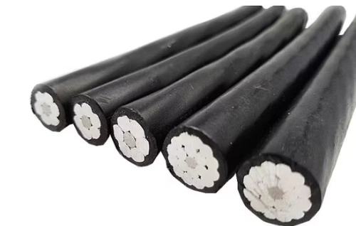
3/0 Cherrystone Aluminum Conductor Triplex Overhead Service Cable
The 3/0 Cherrystone Aluminum Conductor Triplex Overhead Service Cable is engineered to deliver safe, efficient, and durable overhead power distribution for utility networks. It features two insulated aluminum phase conductors helically wrapped around a bare aluminum neutral messenger, providing strong mechanical support and stable electrical performance. Manufactured using premium aluminum materials and high-performance insulation compounds, the 3/0 Cherrystone Aluminum Conductor Triplex Overhead Service Cable offers excellent resistance to corrosion, UV radiation, and environmental stress. Its optimized structure supports easy handling and installation while meeting utility and industry standards. The cable performs reliably under mechanical load, temperature variation, and prolonged outdoor exposure. Strict quality management systems and detailed testing procedures are implemented throughout production to ensure consistent performance and dependable service life.-AL-medium-voltage-power-cable-2.jpg)
RHZ1-OL(AS)-AL Medium Voltage Power Cable(8.7/15kV, 12/20kV, 18/30kV)
RHZ1-OL(AS)-AL Medium Voltage Power Cable (8.7/15kV, 12/20kV, 18/30kV) is a lightweight cable with enhanced fire retardancy for critical medium voltage applications. Featuring stranded aluminium conductors, cross-linked polyethylene (XLPE) insulation, metallic screen, and low smoke zero halogen (LSZH) outer sheath with advanced fire behavior (AS designation), it complies with UNE 21123-4 and higher CPR classifications. In fire scenarios, it produces very low smoke and no toxic gases. Aluminium construction reduces weight and costs while ensuring reliable current capacity. Superior partial discharge resistance, low dielectric losses, and high thermal stability provide efficient, long-lasting performance. Suitable for direct burial, ducts, or indoor use in high-safety areas. The RHZ1-OL(AS)-AL Medium Voltage Power Cable is perfect for utilities, hospitals, schools, tunnels, and infrastructure projects requiring economical, advanced fire-safe medium voltage cabling with exceptional life-safety features and durability worldwide.
ALLIANCE AAAC Conductor Cable
ALLIANCE AAAC (All Aluminum Alloy Conductor) cables are manufactured in strict compliance with international standards such as ASTM B399, IEC 61089, and BS EN 50182, making them a high-performance and reliable overhead power transmission and distribution solution. Meeting ASTM B398, B399, IEC 61089, and BS EN 50182 standards, this cable handles ampacity up to 350A at 75°C and voltages up to 33kV. The all-alloy construction avoids bimetallic corrosion, providing better resistance in harsh conditions than ACSR. Reduced weight minimizes sag and installation expenses, supporting longer spans. The Alliance AAAC Conductor Cable delivers low electrical losses, high mechanical endurance, and excellent weather tolerance. Flame-retardant variants available. Perfect for urban grids, renewable projects, and coastal setups, it provides cost-effective, low-maintenance power delivery in overhead applications globally, excelling in reliability and lifespan over conventional conductors.
3150kVA Three Phase Dry Type Power Transformer Custom Voltage Factory Direct
The 3150kVA Three Phase Dry Type Power Transformer Cast Resin Custom Voltage Factory Direct is a large-capacity, high-efficiency cast-resin dry-type power transformer designed for demanding indoor and semi-outdoor applications in heavy commercial, industrial, data center, renewable energy, mining, railway, and large-scale EV infrastructure projects. Fully compliant with IEC 60076-11, IEC 60076-1/2/3/5/20, EN 50588-1 (eco-design), IEEE C57.12.01, IEEE C57.12.91, UL 1561 (optional), and DOE 2016 efficiency standards, this 3150 kVA dry-type transformer achieves superior energy efficiency (typically 99.35–99.55% at full load), ultra-low no-load and load losses, strong overload capability (up to 150% short-term), low sound levels (<65 dB standard; <60 dB low-noise execution), and a design life exceeding 40 years.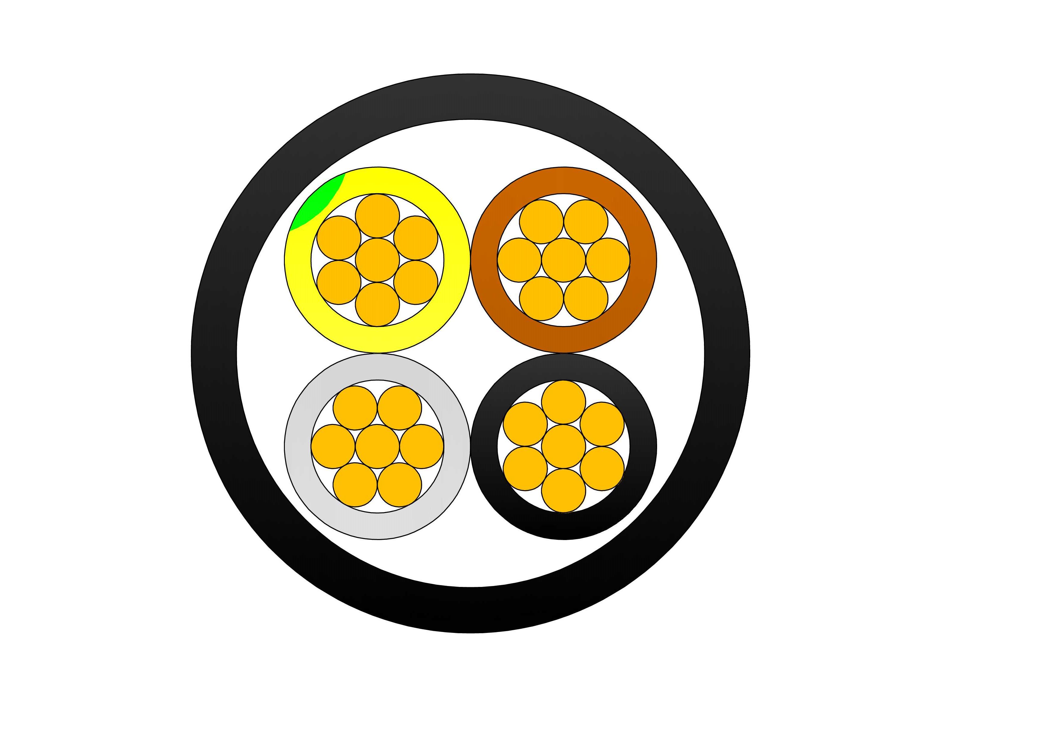
Solar Cable H1Z2Z2-K Tinned Stranded Copper
The H1Z2Z2-K Solar Cable Tinned Stranded Copper is a high-performance photovoltaic cable designed for solar power generation systems. It features tinned stranded copper conductors for superior conductivity, corrosion resistance, and flexibility, with cross-linked polyolefin (XLPO) insulation and sheath providing excellent thermal, UV, ozone, and weather resistance. Rated for 1.8 kV DC, this cable meets TÜV 2PfG 1169 and EN 50618 standards, ensuring safety and durability in harsh outdoor environments. The H1Z2Z2-K Solar Cable Tinned Stranded Copper offers low voltage drop, high current-carrying capacity, and long service life. Its halogen-free, low-smoke, and flame-retardant properties enhance safety in solar farms, rooftop PV systems, and ground-mounted installations. Lightweight and flexible, it simplifies installation while maintaining reliable performance in extreme temperatures and weather conditions.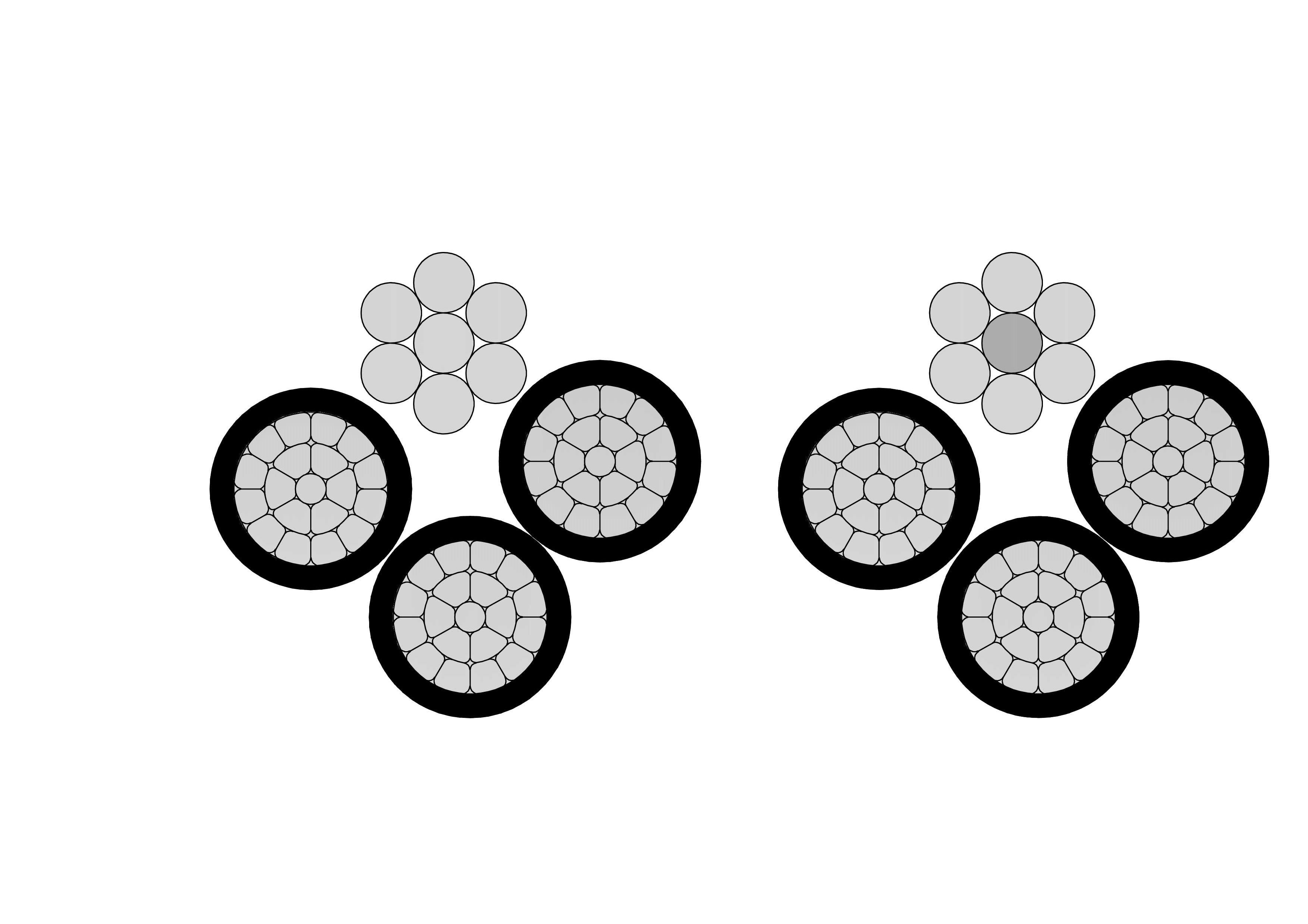
3/0 Suffolk Aluminum Conductor Quadruplex Overhead Service Drop Cable
The 3/0 Suffolk Quadruplex Service Drop Cable is a robust overhead cable for three-phase secondary power distribution with neutral. Featuring three 3/0 AWG aluminum phase conductors and one neutral messenger (7-strand) insulated with XLPE or PE and assembled in quadruplex configuration, it offers excellent mechanical strength and weather resistance. Compliant with ASTM B-230, B-231, ICEA S-76-474, and ANSI/ICEA standards, this cable supports 600V applications with superior UV, moisture, and abrasion protection. The self-supporting messenger reduces sag and simplifies installation over medium spans. The 3/0 Suffolk Quadruplex Service Drop Cable ensures low power losses, high current capacity, and long service life in harsh outdoor conditions. Lightweight and flexible, it is widely used for three-phase service drops in residential subdivisions, commercial buildings, and rural areas requiring safe, cost-effective aerial connections from utility poles to service entrances.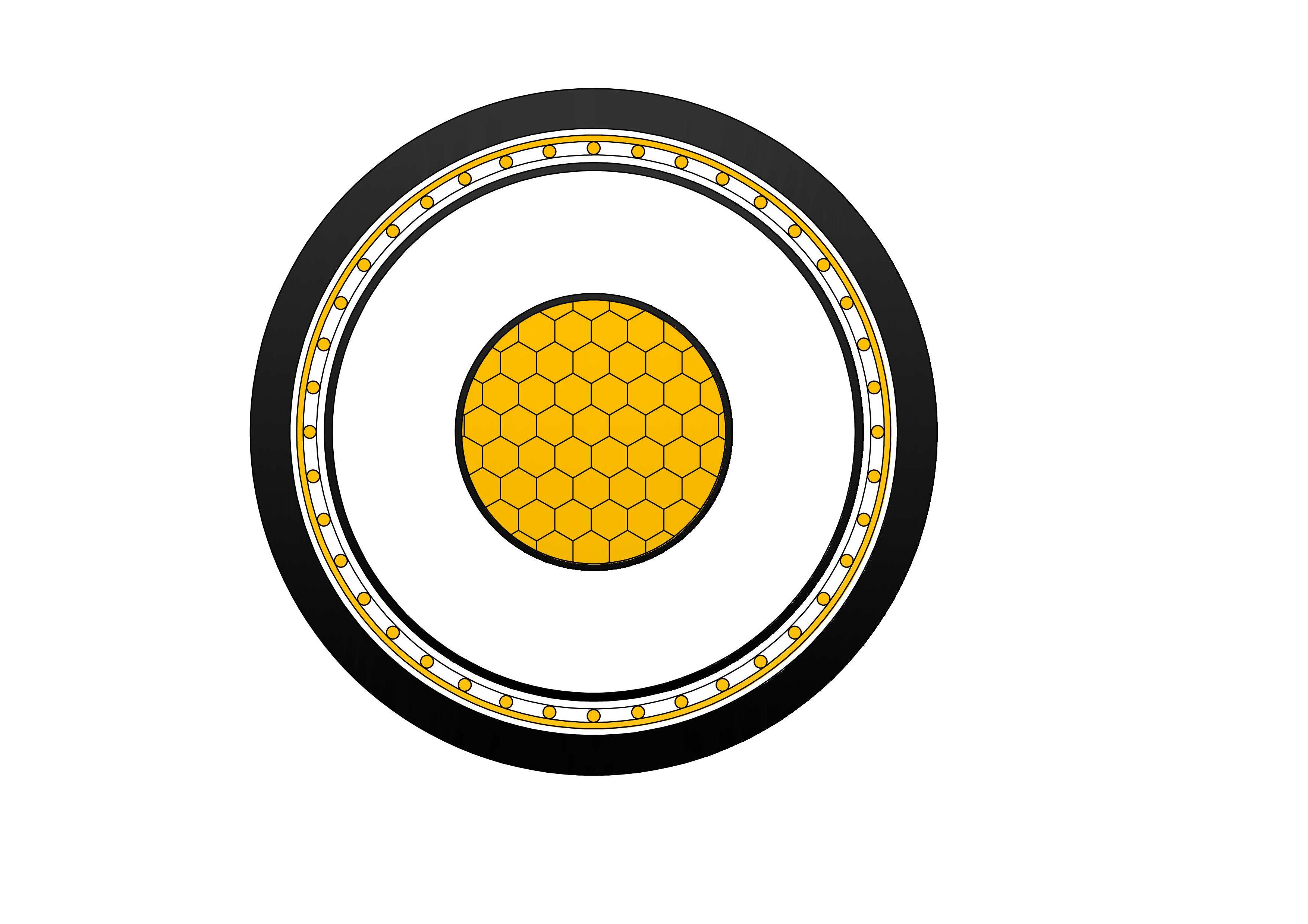
N2XS(F)2Y Medium Voltage Power Cable(6/10kV, 12/20kV, 18/30kV)
The N2XS(F)2Y Medium Voltage Power Cable is engineered for reliable power transmission in medium voltage networks operating at 6/10kV, 12/20kV, and 18/30kV. The cable features a copper conductor, XLPE insulation, and a longitudinally corrugated aluminum sheath that provides excellent moisture barrier performance and mechanical protection. The outer polyethylene sheath enhances resistance to chemicals, abrasion, and environmental stress. Designed in accordance with IEC standards, N2XS(F)2Y cables offer low dielectric losses, stable electrical performance, and long service life. The aluminum sheath also serves as an effective metallic screen, improving fault current capability and system safety. This construction makes the cable suitable for underground and outdoor installations where high reliability and environmental protection are essential.
3+2 Cores Copper Cable CU/XLPE/PVC 0.6/1kV
The Single Core Copper Cable CU/XLPE/PVC 0.6/1kV is engineered for reliable power transmission and distribution in industrial, commercial, and utility applications. Featuring a high-purity copper conductor, XLPE insulation, and durable PVC outer sheath, the cable delivers outstanding electrical conductivity, thermal stability, and mechanical protection. The XLPE insulation offers superior dielectric properties, allowing the cable to operate continuously at conductor temperatures up to 90°C while maintaining excellent insulation performance. The PVC sheath provides resistance against moisture, abrasion, chemicals, and environmental exposure, ensuring a long service life even in demanding installations. Designed according to international standards including IEC 60502-1, this cable is suitable for fixed installations in power networks, industrial facilities, commercial buildings, renewable energy projects, and infrastructure developments. Various conductor sizes and sheath colors can be customized to meet specific project requirements. Its combination of safety, durability, and efficient power transmission makes the Single Core Copper Cable CU/XLPE/PVC 0.6/1kV a dependable solution for modern electrical systems.
H07ZZ-F EN 50525-3-21 LSZH Rubber Flexible Cable
The H07ZZ-F Rubber Flexible Cable is a high-performance low-smoke, halogen-free (LSZH) flexible cable designed in compliance with EN 50525-3-21 and IEC 60502-1 standards. It offers outstanding flexibility, flame retardancy, and resistance to smoke and toxic gas emission, ensuring enhanced safety in public and industrial environments. With its cross-linked LSZH insulation and sheath, the H07ZZ-F cable is ideal for fixed and mobile electrical installations in airports, subways, public buildings, power distribution systems, UPS equipment, and stage lighting setups. Engineered to perform under moderate mechanical stress, it maintains excellent reliability both indoors and outdoors. The H07ZZ-F LSZH is ideal for mobile equipment, construction sites, mining, public buildings, and industrial power supply where low smoke, halogen-free safety, and flexibility are critical for fire-sensitive or confined spaces.
4 Hackney Aluminum Conductor Quadruplex Overhead Service Drop Cable
4 Hackney Quadruplex Service Drop Cable is a robust overhead cable for three-phase secondary power distribution with neutral. Featuring three 4 AWG aluminum phase conductors and one neutral messenger (7-strand) insulated with XLPE or PE and assembled in quadruplex configuration, it offers excellent mechanical strength and weather resistance. Compliant with ASTM B-230, B-231, ICEA S-76-474, and ANSI/ICEA standards, this cable supports 600V applications with superior UV, moisture, and abrasion protection. The self-supporting messenger reduces sag and simplifies installation over medium spans. The 4 Hackney Quadruplex Service Drop Cable ensures low power losses, high current capacity, and long service life in harsh outdoor conditions. Lightweight and flexible, it is widely used for three-phase service drops in residential subdivisions, commercial buildings, and rural areas requiring safe, cost-effective aerial connections from utility poles to service entrances.
10 Gauge Galvanized Steel Conductor Wire
The 10 Gauge Galvanized Steel Conductor Wire is a premium high-strength bare steel wire designed for reliable overhead power line applications. Manufactured with heavy hot-dip zinc coating, this 10 AWG galvanized conductor delivers superior corrosion resistance and long service life in harsh outdoor environments. It offers excellent tensile strength and mechanical performance, making it ideal for use as overhead ground wire (static wire), guy wire, or messenger wire. Fully compliant with ASTM A475 and related utility standards, the 10 Gauge Galvanized Steel Conductor Wire undergoes rigorous testing from raw materials to finished product to ensure uniform zinc adhesion, consistent diameter, and high breaking strength. Its durable construction minimizes maintenance while providing dependable shielding and structural support for transmission and distribution systems.
YSLCY / HSLCH CY Control Cable - 300/500V Screened Flexible Cable
The CY Control Cable (YSLCY / HSLCH) is a versatile screened flexible control cable ideal for industrial environments where electromagnetic interference protection is essential. It consists of finely stranded copper conductors with PVC or LSZH insulation, twisted cores, a high-coverage tinned copper braid screen, and a robust PVC or LSZH outer sheath. The YSLCY version is suited for general industrial use, while the HSLCH version provides enhanced fire safety with low smoke and zero halogen properties. Rated 300/500V, this cable offers excellent flexibility, oil resistance, and reliable signal transmission. The CY Control Cable (YSLCY / HSLCH) is manufactured under strict quality control from raw materials to finished product, meeting international standards for performance and safety in automation and control applications.
15kV 3-Layer AAAC/ACSR/AAC Tree Wire - Triple Layer Covered Conductor
The 3-Layer 15kV AAAC/ACSR/AAC Tree Wire is a specialized covered overhead conductor developed for distribution lines in areas with dense vegetation. It uses concentrically stranded AAAC, ACSR, or AAC conductors protected by a triple-layer system of track-resistant HDPE or XLPE. The multi-layer covering delivers exceptional tracking resistance, abrasion protection, and weatherability while greatly reducing the risk of electrical faults from tree limb contact and helping minimize wildfire ignition potential. This advanced design allows closer spacing to vegetation and lowers vegetation management costs. Suitable for conventional overhead or spacer cable systems, the 3-Layer 15kV AAAC/ACSR/AAC Tree Wire offers a cost-effective solution for improving line reliability. It complies with ICEA and ASTM standards and undergoes extensive quality testing to ensure long-term performance and safety.
15kV Copper Conductor URD Cable - MV Underground Distribution Cable
The 15kV Copper Conductor URD Cable is a premium medium-voltage underground distribution cable designed for high-reliability primary and secondary power delivery. It features a stranded high-conductivity copper conductor, extruded semi-conducting shields, tree-retardant TR-XLPE or EPR insulation, and a full copper concentric neutral, all protected by a tough sunlight-resistant LLDPE jacket. This construction provides superior electrical performance, excellent moisture and treeing resistance, and strong mechanical protection suitable for direct burial or duct installations. The high-conductivity copper conductor ensures lower losses and higher ampacity. Manufactured to ICEA S-94-649 and AEIC CS8 standards, the 15kV Copper Conductor URD Cable undergoes rigorous quality testing from raw materials to finished product, ensuring long-term reliability and safety in demanding underground environments.Welcome your inquiry
Honesty, Integrity, Frugality, Activeness and Passion