



Medium Voltage Switchgear
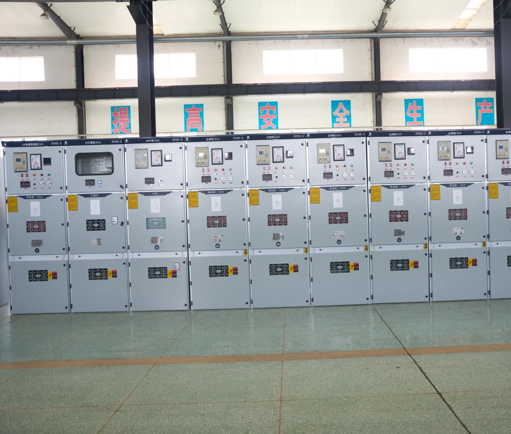
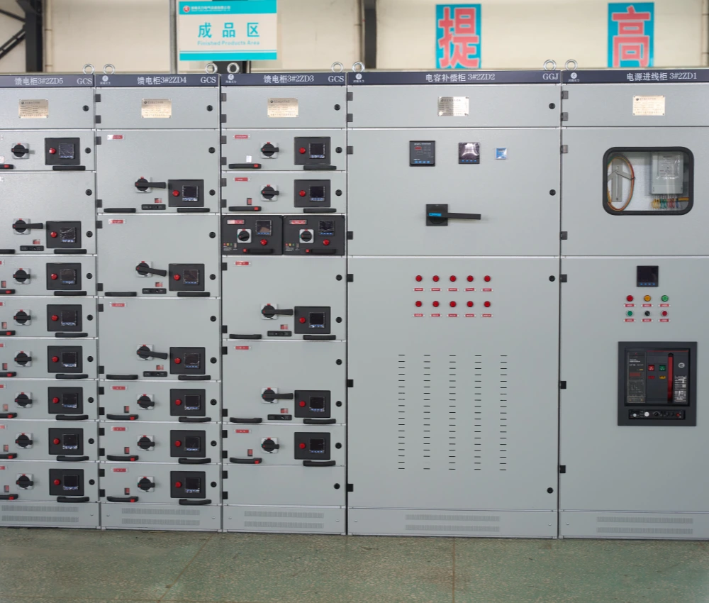
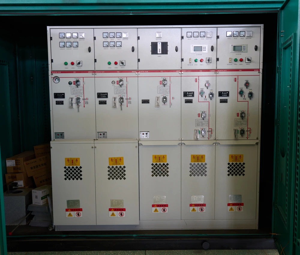
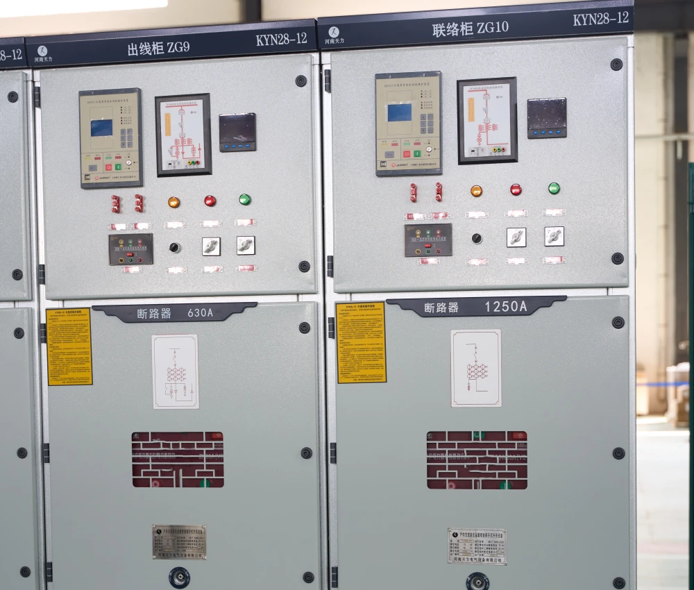
The Medium Voltage Switchgear is an advanced electrical distribution and protection system engineered for safe, reliable, and efficient medium-voltage power management in utility substations, industrial facilities, renewable energy plants, commercial infrastructure, and smart-grid applications. The system integrates vacuum circuit breakers, disconnect switches, protection relays, busbar assemblies, intelligent monitoring systems, and automation devices into a compact modular enclosure structure to ensure stable electrical distribution and enhanced operational safety. Designed with high-strength insulated structures and precision-manufactured electrical components, the medium voltage switchgear provides outstanding dielectric performance, thermal stability, and mechanical durability under demanding operating conditions. Its modular cabinet configuration improves installation flexibility, simplifies maintenance procedures, and supports future power distribution expansion while minimizing operational downtime and maintenance costs. The Medium Voltage Switchgear supports air-insulated and gas-insulated configurations, intelligent automation systems, remote communication protocols, and smart-grid integration technologies. With customizable protection schemes and scalable electrical distribution capabilities, the switchgear delivers dependable medium-voltage control and protection performance for industrial automation systems, utility power networks, renewable energy integration projects, transportation infrastructure, and mission-critical electrical facilities.
- Primary Voltage Ratings 3.3kV / 6kV / 11kV / 22kV / 33kV
- Type Switchgear
- Standards IEC 62271 / ANSI / IEEE
- Application smart-grid systems, data centers, hospitals, petrochemical plants
- Certificate UL, CESI, IEEE
- Cooling Method ONAN / ONAF
Technical Specifications
Customization Optional
Packing and Shipping
Manufacturer Test
Routine Testing
Application
Technical Specifications
Medium Voltage Switchgear
Medium Voltage Switchgear Data Sheet
| Parameter Category |
Technical Parameter |
Specification Range / Typical Value | Unit | Remarks / Standard |
| Rated Voltage | Ur | 7.2 / 12 / 17.5 / 24 / 36 | kV | IEC 62271-1 |
| Rated Current | Ir | 630 / 1250 / 1600 / 2000 / 2500 / 3150 | A | Busbar & Breaker |
| Rated Short-time Withstand Current | Ik | 16 / 20 / 25 / 31.5 / 40 | kA | 3s or 4s |
| Peak Withstand Current | Ip | 40 / 50 / 63 / 80 / 100 | kA | Peak value |
| Rated Short-Circuit Breaking Current | Isc | 16 / 20 / 25 / 31.5 / 40 | kA | Vacuum / SF6 Breaker |
| Power Frequency Withstand Voltage | Ud | 28 / 38 / 50 / 70 / 85 | kV | 1 minute |
| Lightning Impulse Withstand Voltage | Up | 75 / 95 / 125 / 145 / 170 / 200 | kV | 1.2/50μs |
| Insulation Medium | - | SF6 Gas / Vacuum / Air | - | GIS / AIS |
| Protection Degree | IP Code | IP4X (Indoor) / IP54 (Outdoor) | - | Enclosure |
| Operating Mechanism | - | Spring / Magnetic Actuator / Motorized | - | Circuit Breaker |
| Mechanical Endurance | M | 10,000 – 30,000 | Operations | Breaker |
| Internal Arc Classification | IAC | AFL / AFLR up to 40kA / 1s | - | Optional |
| Frequency | f | 50 / 60 | Hz | Standard |
| Ambient Temperature | - | -25°C to +40°C (Special: -40°C to +55°C) | °C | Outdoor type |
| Installation Type | - | Indoor Metal Clad / Outdoor / RMU / Kiosk | - | Customizable |
| Smart Monitoring | - | IEC 61850, PD Monitoring, Gas Density, Temp Scan | - | Optional |
Customization Optional
Medium Voltage Switchgear
Our medium voltage switchgear provides extensive customization to address specific project demands across various industries. Customers can select between Air Insulated Switchgear (AIS), Gas Insulated Switchgear (GIS), or Ring Main Units (RMU) with single or double busbar configurations. We offer tailored current and short-circuit ratings, along with different breaker technologies including vacuum interrupters or environmentally friendly alternatives. Enclosure designs can be modified for width, height, depth, and color to fit space constraints, while cable or bus duct entry points are fully adaptable. Advanced options include arc-resistant designs, integrated voltage transformers, current transformers, and surge arresters precisely matched to system requirements.
We also support smart grid integration with custom communication protocols, remote monitoring systems, and predictive maintenance features. For challenging environments, we provide enhanced corrosion protection, seismic reinforcement, and extreme temperature adaptations. Our engineering team works collaboratively with clients from initial design through to final validation, ensuring seamless integration with existing infrastructure. This high level of customization allows us to deliver medium voltage switchgear solutions that maximize reliability, safety, and operational efficiency while fully complying with IEC 62271, GB/T 11022, and other international standards for long-term performance.
Packing and Shipping
Medium Voltage Switchgear
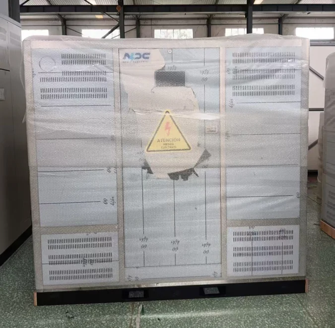
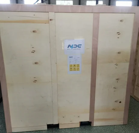
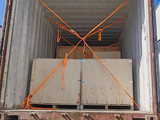
We apply rigorous standards in packing and shipping medium voltage switchgear to safeguard equipment during transit. Each MV switchgear panel and module is packed in robust export-grade wooden crates reinforced with steel brackets and impact-absorbing padding. Critical components like vacuum circuit breakers, busbars, and instrument transformers are individually protected with anti-static wrapping, foam molds, and moisture-absorbing desiccants. All enclosures are sealed with protective covers, and fragile electronic parts receive additional cushioning to withstand rough handling and long-distance transportation.
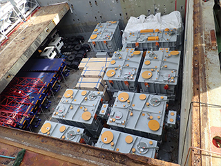
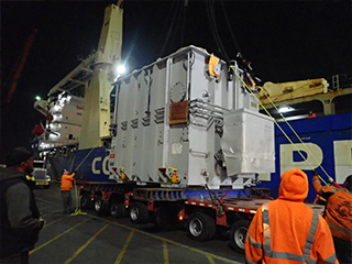
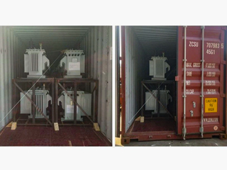
Shipping arrangements are tailored to project timelines and locations. For domestic transport, we utilize specialized heavy-duty vehicles with proper securing systems and real-time monitoring. International shipments are executed through trusted freight partners using 40-foot containers or break-bulk vessels when necessary, with full cargo insurance and complete export documentation. We ensure compliance with all hazardous material regulations related to insulating gases.
Our logistics team provides end-to-end coordination, including pre-shipment inspections, container sealing, and GPS tracking for transparency. Customers receive regular updates on shipment status, expected arrival times, and customs clearance progress. For urgent requirements, we offer air freight solutions with specialized packaging to maintain equipment integrity.
Sustainability is integrated into our packing practices through the use of recyclable materials and returnable crates where possible. Upon delivery, we supply detailed unpacking instructions and can arrange on-site technical support for installation teams. This comprehensive packing and shipping process minimizes transit risks and ensures your medium voltage switchgear arrives ready for efficient deployment and commissioning.
Shipping arrangements are tailored to project timelines and locations. For domestic transport, we utilize specialized heavy-duty vehicles with proper securing systems and real-time monitoring. International shipments are executed through trusted freight partners using 40-foot containers or break-bulk vessels when necessary, with full cargo insurance and complete export documentation. We ensure compliance with all hazardous material regulations related to insulating gases.
Our logistics team provides end-to-end coordination, including pre-shipment inspections, container sealing, and GPS tracking for transparency. Customers receive regular updates on shipment status, expected arrival times, and customs clearance progress. For urgent requirements, we offer air freight solutions with specialized packaging to maintain equipment integrity.
Sustainability is integrated into our packing practices through the use of recyclable materials and returnable crates where possible. Upon delivery, we supply detailed unpacking instructions and can arrange on-site technical support for installation teams. This comprehensive packing and shipping process minimizes transit risks and ensures your medium voltage switchgear arrives ready for efficient deployment and commissioning.
32
32 years of industry experience
Manufacturer Test
Medium Voltage Switchgear
Progress Test
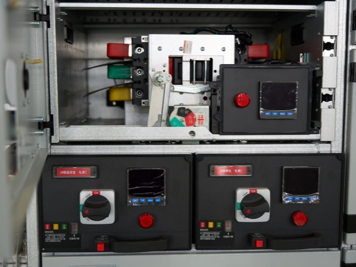
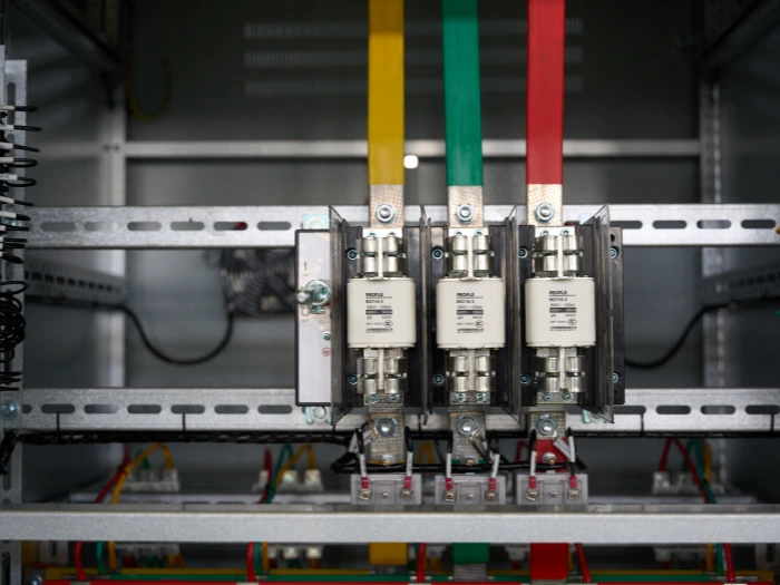
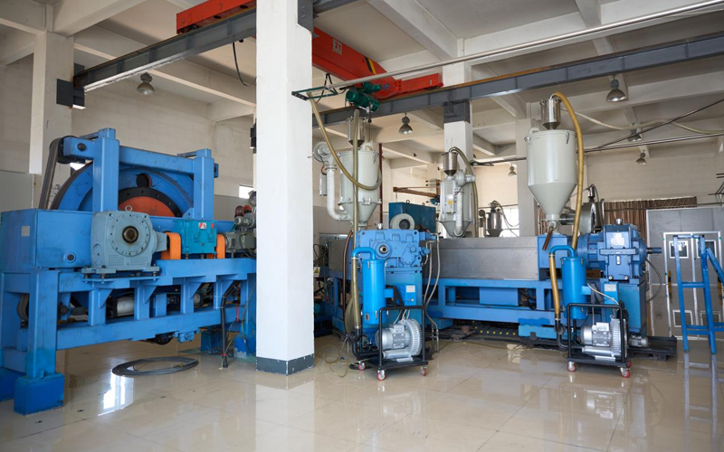
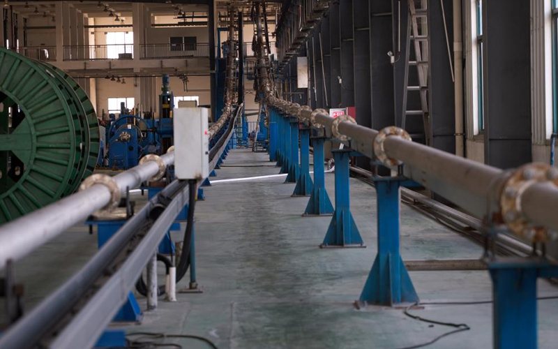
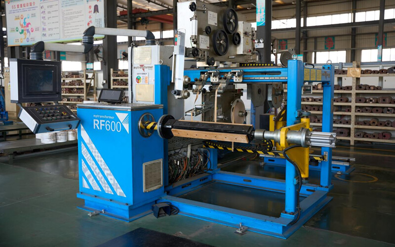
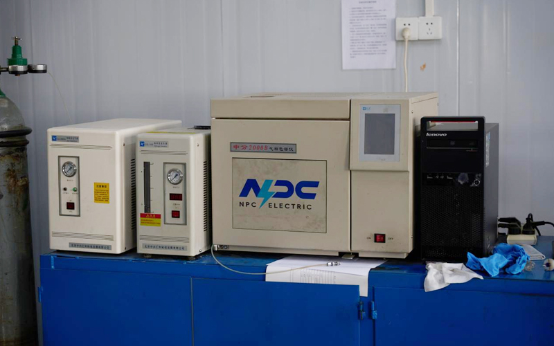
The manufacturing progress testing procedure for the Medium Voltage Switchgear is implemented throughout all critical production stages to ensure assembly precision, electrical reliability, and operational safety. Initial inspections focus on raw material verification including enclosure steel thickness measurement, insulation material testing, busbar conductivity analysis, and surface coating inspection to confirm compliance with engineering specifications and international manufacturing standards. During cabinet fabrication and electrical assembly, engineers inspect welding quality, compartment alignment, grounding continuity, cable routing structures, ventilation systems, and enclosure sealing integrity. The installation of vacuum circuit breakers, disconnect switches, busbar assemblies, protection relays, metering devices, and intelligent control modules is carefully monitored to ensure proper electrical clearances and maintenance accessibility. Internal wiring systems are additionally verified according to approved technical drawings to minimize installation errors and improve commissioning efficiency.
Design Tests
All transformers will be tested after finishing the production, test items as follows:
♦ Insulation Power Factor
♦ Ratio, Polarity, and Phase Relation
♦ Winding Resistance
♦ Impulse Tests
♦ On load Loss Test
♦ No Load Loss Test
♦ Transformer Turns Ratio/TTR (All Tap Voltages)
♦ Impedance Voltage & Load Loss (Rated Voltage)
♦ Polarity, 1-Ph / Phase Relation, 3-Ph (Rated Voltage)
♦ Excitation & No-Load Loss (Rated Voltage)
♦ Applied Voltage
♦ Induced Voltage
♦ Lightning Impulse
♦ Insulation Resistance (Rated Voltage)
♦ Temperature Rise
♦ Dielectric Withstand (Hipot)
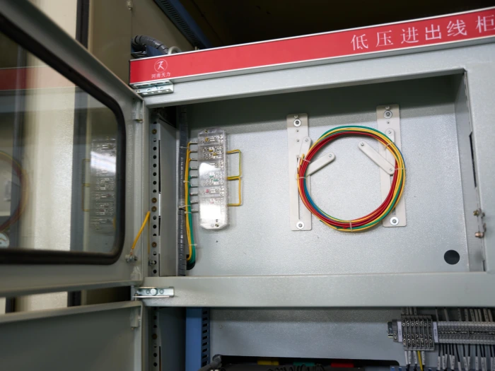
Factory Acceptance Test
The transformer Factory Acceptance Test program for transformer-integrated Medium Voltage Switchgear systems is designed to guarantee manufacturing quality consistency and dependable field operation in industrial and utility power distribution applications. The testing procedure begins with visual inspections and dimensional verification of transformer tanks, bushings, grounding terminals, cooling systems, enclosure coating quality, and accessory installation to confirm conformity with approved engineering drawings. Protective devices and auxiliary systems including pressure relief valves, oil level indicators, thermal protection devices, cooling fans, alarm systems, and intelligent communication interfaces are functionally tested to verify reliable operation during abnormal electrical conditions. SCADA integration modules and remote monitoring systems are also tested for projects requiring advanced energy management and smart-grid connectivity.
Routine Test - Dielectric Withstand Voltage Test (AC)
Purpose of Testing
Evaluate the integrity of the main circuit insulation and contact connections. Identify potential defects such as moisture ingress, aging, or contamination in the insulation system, and verify that contact resistance is within acceptable limits to prevent overheating.
Testing Equipment
For Insulation Resistance: Megohmmeter (typically 2500V or 5000V DC).For Circuit Resistance: Micro-ohmmeter (DC resistance tester) or Precision DC current source.Auxiliary Tools: Thermometer/hygrometer (for temperature correction).
Pre-Test Preparation
Ensure the switchgear is de-energized, isolated, and properly grounded. Clean the test terminals and bushings to remove dust or moisture. For insulation tests, discharge all capacitive loads (cables, busbars) thoroughly through the grounding switch or shorting links.
Test Progress
1. Insulation Test: Connect the megger leads to the busbar phases and ground. Apply the test voltage (e.g., 2500V DC) and hold for 1 minute.2. Circuit Resistance Test: Connect the micro-ohmmeter current leads to the main busbar or circuit breaker terminals. Pass a low DC current (e.g., 100A) and record the voltage drop.
Temperature Correction
Correct the measured insulation resistance to a standard reference temperature (typically 20°C) using the appropriate exponential formula to ensure compliance with standards across different ambient conditions.
Circuit Resistance Test
Connect the tester leads to the main busbar or circuit breaker terminals. Pass a low DC current (e.g., 100A or 200A as per standard) and accurately record the voltage drop across the connection point. Ensure the equipment is energized only if it complies with specific hot-line testing safety protocols, otherwise perform cold-resistance measurement after de-energization
Mechanical Characteristic Test
Purpose: To verify the operational performance and timing of the circuit breaker mechanism, ensuring compliance with speed and travel requirements for arc extinction.Procedure: Use a dedicated Circuit Breaker Mechanical Tester. Connect the tester to the control circuit (closing/opening coils) and the secondary side of the travel transducer. Perform several opening and closing operations without load. Record key parameters: Opening/Closing time, Synchronization between three phases, Travel distance, Overshoot, and Contact pressure.
Power Frequency Withstand Test (AC Hipot)
Purpose: To validate the integrity of the main insulation system under high voltage stress.Equipment: AC high voltage test set.Procedure: Energize the equipment and apply the specified power frequency test voltage (e.g., 42kV for 1 minute for 10kV switchgear) between phases/inter-phase and ground. Monitor the leakage current. The test is considered passed if the insulation does not break down and the current remains stable within the standard limit. (Note: This is a destructive test; perform only on de-energized and properly discharged equipment).
Partial Discharge (PD) Measurement
Purpose: To identify internal insulation defects such as voids, cracks, or contamination that are not detectable by insulation resistance tests.Procedure: Inject the test voltage up to 1.3~1.5 times the rated voltage. Use a PD detector connected to the coupling capacitor or directly to the test object to measure the apparent charge (pC). Ensure the background noise level is below the detection threshold. Analyze the PD patterns to locate the faulty chamber.
*These comprehensive tests ensure that each transformer meets performance standards and operates
reliably under various conditions.
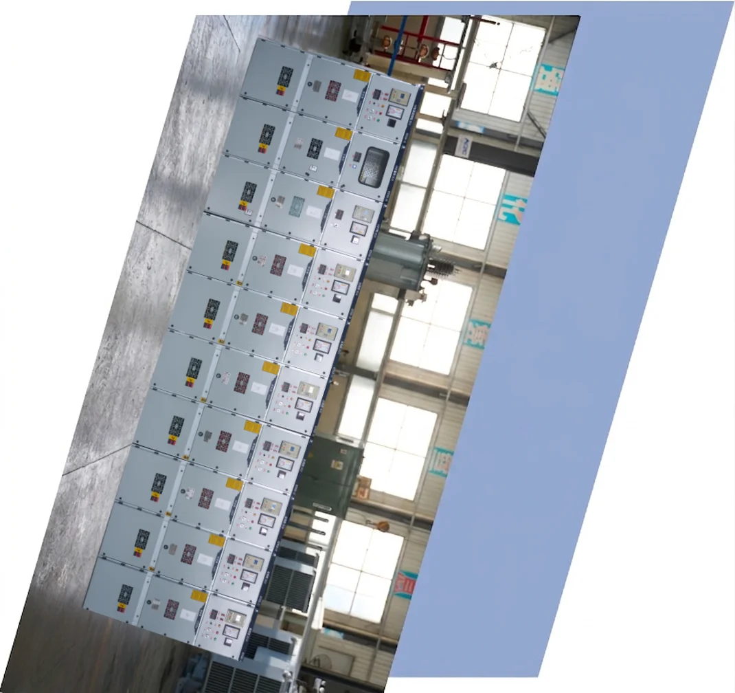
Application
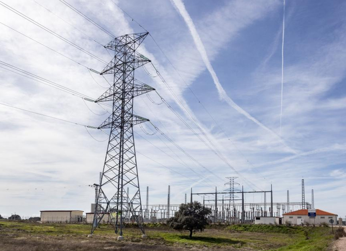
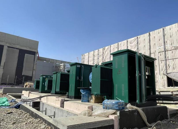
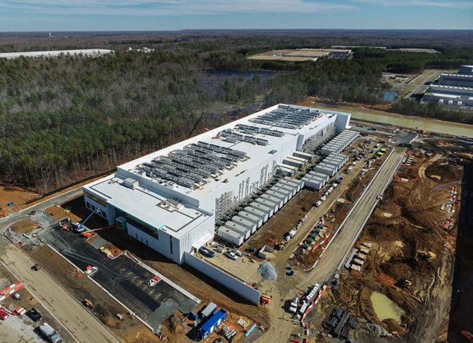
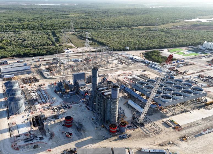
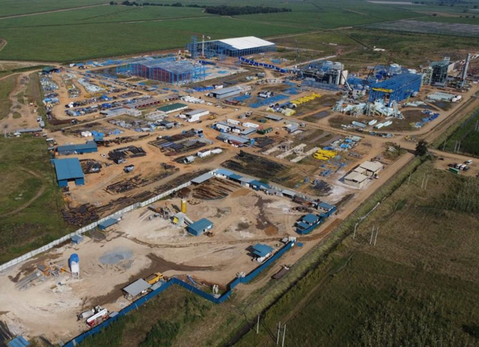
This MV switchgear performs excellently in wind and solar renewable energy substations, metro and railway traction power systems, water and wastewater treatment plants, and hospital campus microgrids. It is well-suited for chemical processing facilities and large-scale EV charging network infrastructure.



Technical Advantages
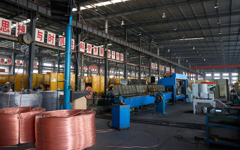
● 30+ years of manufacturing experience
● ISO and UL certified production
● Customized cable and transformer solutions

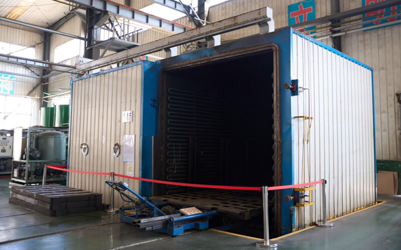
Product Packaging
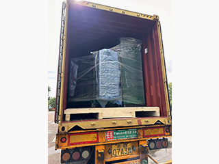
Transformers Packaging (1)
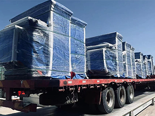
Transformers Packaging (2)
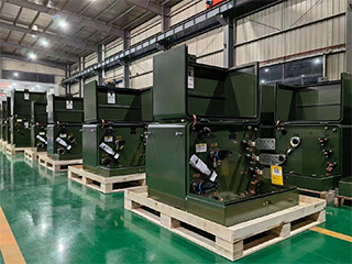
Transformers Packaging (3)
Transformers Packaging (4)
Transformers Packaging (5)
Transformers Packaging (6)
Transformers Packaging (7)
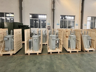
Transformers Packaging (8)
Related Products
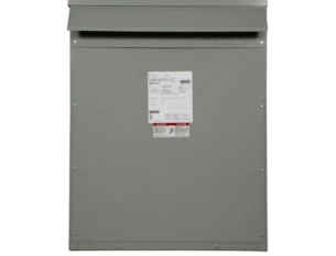
10kVA Isolation Transformer - 120V to 240V
The 10kVA Isolation Transformer – 120V to 240V is specifically engineered to provide safe voltage conversion and complete electrical isolation for critical power applications. Designed to convert a 120V input supply into a stable 240V output while maintaining galvanic separation between the primary and secondary circuits, this transformer significantly improves power quality, reduces electrical noise, and protects connected equipment from voltage disturbances, ground loops, and transient surges. Featuring a high-efficiency silicon steel core and precision-engineered copper windings, the transformer delivers stable output voltage, low operating losses, and exceptional thermal performance. The isolation design effectively suppresses electromagnetic interference (EMI) and common-mode noise, making it particularly suitable for sensitive equipment such as industrial controllers, laboratory instruments, communication systems, medical equipment, and testing devices. The robust construction ensures reliable operation under continuous load conditions while minimizing maintenance requirements. The 10kVA Isolation Transformer is available in both open-frame and enclosed configurations, offering installation flexibility across industrial facilities, commercial buildings, telecom infrastructure, manufacturing plants, and specialized power distribution systems. Its durable design, high efficiency, and superior safety performance make it a dependable solution for voltage conversion and electrical isolation applications.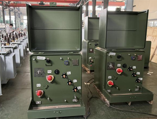
11kV Single Phase Pole Mounted Transformer
The 11kV single phase pole mounted transformer is a compact, high-performance solution for overhead distribution systems, stepping down 11kV primary voltage to standard secondary levels like 230V, 240V, or 415V for safe end-user supply. Built with high-grade silicon steel cores and copper or aluminum windings, it minimizes core and copper losses while meeting IEC 60076 and relevant IEEE/ANSI standards for energy efficiency. The oil-immersed tank with ONAN natural cooling supports a 55-65°C temperature rise, ensuring reliable operation under varying loads. Features include robust bushings, pressure relief mechanisms, and optional surge protection, making it weather-resistant and low-maintenance for exposed pole installations. This transformer excels in providing stable, low-distortion power with excellent overload tolerance, perfect for utilities expanding access in diverse terrains.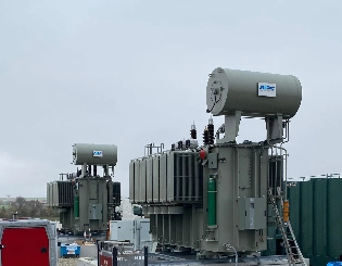
260 kV 20MVA 28 MVA Substation Power Transformer
The robust 260 kV 20/28 MVA substation power transformer, engineered for high-voltage applications in modern electrical grids. This oil-immersed unit features dual capacity ratings for flexible operation under varying loads, ensuring efficient power distribution and voltage step-down in utility substations. With advanced insulation systems and low-loss core materials, it minimizes energy dissipation while handling peak demands reliably. Ideal for integrating renewable energy sources or industrial power systems, this transformer complies with IEC 60076 standards, offering superior performance in harsh environments. Its compact design facilitates easy installation, making it a top choice for upgrading aging infrastructure or expanding grid capacity.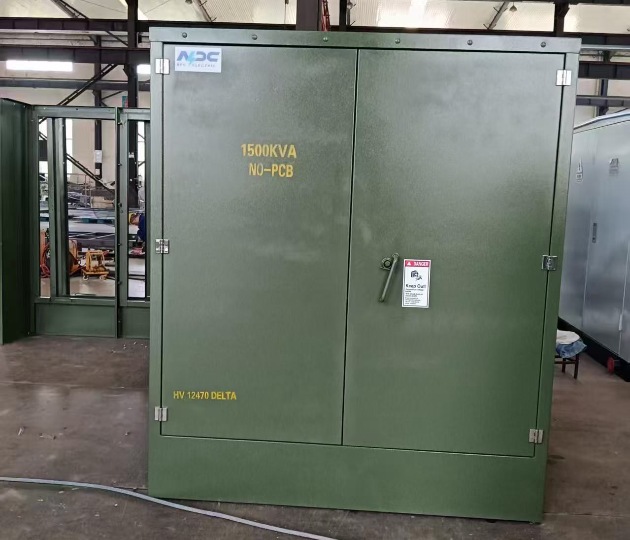
1500kVA Radial Feed Pad Mounted transformer DOE 2016
The 1500kVA Radial Feed Pad-Mounted Transformer is designed for reliable medium-voltage power distribution in utility, commercial, and renewable energy (solar) applications. Engineered to comply with IEEE C57.12.34, C57.12.24, C57.12.00, and DOE 2016 efficiency standards, this pad-mounted transformer is ideal for step-down applications from 12.47kV to 480/277V. Standard features include mineral oil or FR3 natural ester fluid (ONAN cooling), aluminum or copper windings, primary voltage 13.8kV (13800V Delta or 12470GrdY/7200 common), secondary 480Y/277V (or 208Y/120V, custom options), BIL 95kV HV / 30kV LV, impedance 5.75–7.0% (±7.5%), ±2×2.5% taps, radial-feed dead-front design with three high-voltage bushings (H1, H2, H3), bayonet fuses + partial-range current-limiting fuses, load-break switch (optional), lightning arresters, pressure relief valve, oil level/temperature gauges, and ANSI 70 gray (or Munsell green) finish.
22kV Dry Type Transformer Cast Resin Three Phase Distribution Transformer
22kV Dry Type Transformer Cast Resin Three Phase Distribution Transformer, a premium oil-free solution engineered for safe, reliable medium-voltage power distribution in indoor environments. This three-phase cast resin transformer features fully vacuum-impregnated epoxy resin windings with high-conductivity copper conductors and premium low-loss grain-oriented silicon steel cores, achieving superior energy efficiency (typically 98.5%+), significantly reduced no-load and load losses, and excellent partial discharge performance (<10pC). The advanced cast resin encapsulation provides outstanding moisture resistance, self-extinguishing fire safety (F1 class), robust short-circuit withstand capability, and completely maintenance-free operation. Natural air (AN) cooling with optional forced air (AF) upgrades supports high overload capacity, while optimized core clamping, vibration-dampening mounts, and noise-reduction design deliver low acoustic levels suitable for urban or sensitive installations.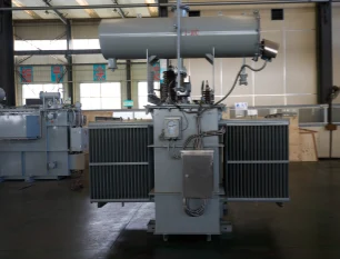
37kV 10000kVA(10MVA) Three Phase Duplex Winding Oil Immersed Power Transformer
The 37kV 10000kVA (10MVA) Three Phase Duplex Winding Oil Immersed Power Transformer is designed for high-reliability medium-voltage distribution and industrial applications. Featuring 99.95% electrolytic copper duplex windings, advanced ONAN/ONAF cooling, and ±8×1.25% on-load tap changer (optional), it delivers ultra-low no-load and load losses (S11/S13 series). Fully compliant with IEC 60076, GB/T 1094, and ANSI/IEEE standards, it withstands 170–200 kV lightning impulse and PD <10 pC. Corrugated tank or detachable radiator design ensures excellent heat dissipation and mechanical strength. Standard voltages 37±8×1.25%/11kV, 37/6.3kV or custom. Vacuum oil processing and nitrogen sealing guarantee 30+ years service life with minimal maintenance. Trusted by utilities, EPCs, and heavy industries worldwide.FAQ From Customers
-
What is a Transformer?A transformer is an electrical device used to change the voltage of alternating current (AC). It works on the principle of electromagnetic induction, converting high-voltage current into low-voltage current or low-voltage current into high-voltage current. Transformers are widely used in power transmission, distribution systems, and various electronic devices.
-
What are the main uses of a transformer?The main use of a transformer is voltage conversion. Transformers are used in power transmission systems to help transfer electricity from power plants to consumers. In addition, transformers are also used in electronic devices such as chargers, televisions, power adapters, etc., to adjust the voltage to meet the requirements of different devices.
-
Do you have UL listed?Yes, our transformer has UL listed. We have exported to America many pad mounted transformer,substation transformer and HV.
Welcome your inquiry
Honesty, Integrity, Frugality, Activeness and Passion