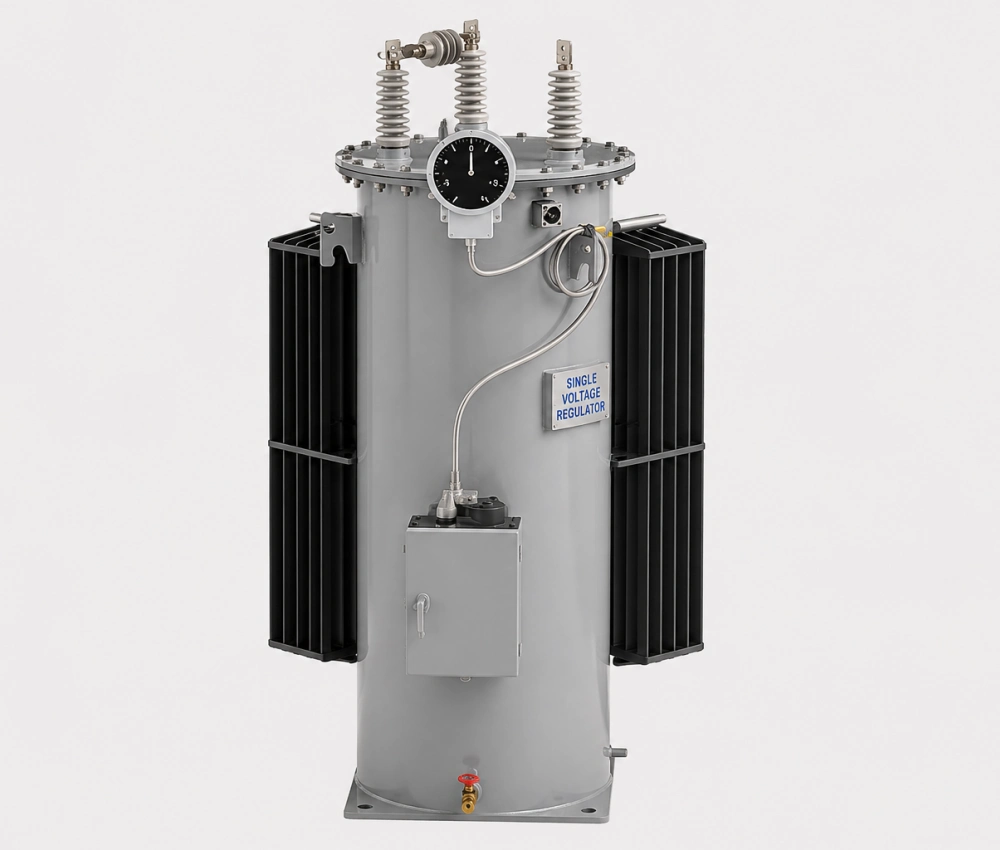
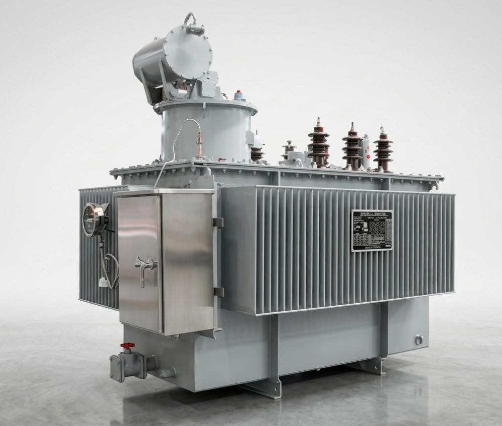


Single Phase Automatic Step Voltage Regulator
The Single-phase Automatic Step Voltage Regulator is an advanced, intelligent voltage stabilization device designed to automatically correct voltage fluctuations and deliver stable output for sensitive electrical equipment. Utilizing a high-efficiency toroidal or laminated core with premium copper windings and multiple tap positions, this regulator provides fast, precise step-type voltage correction (±10% to ±30% input range) with response times under 1 second. It features a microprocessor-based digital controller with LCD display, multiple protection functions (over-voltage, under-voltage, overload, short-circuit, and surge), and automatic bypass capability. Built with robust construction and high overload capacity (up to 200% for short durations), it ensures reliable performance in varying load conditions while maintaining low waveform distortion and high efficiency (>98%). Ideal for single-phase 220V/230V/240V systems, this voltage regulator is widely used in residential, commercial, and light industrial applications to protect equipment from unstable grid voltage and extend service life.
- Primary Voltage Ratings 15kV / 33kV class (50Hz)
- Secondary Voltage Ratings --
- H.V. Tap Range --
- Type Voltage Regulator
- BIL 11kV - 200kV
- Standards IEC 60076, IEC 60137, ASTM D202
- Application residential, commercial, industrial voltage stabilization
- Power Rating --
- Certificate UL, CESI, IEEE
- Cooling Method Natural Air Cooling
- Opeartion --
Technical Specifications
Customization Optional
Packing and Shipping
Manufacturer Test
Routine Testing
Application
Technical Specifications
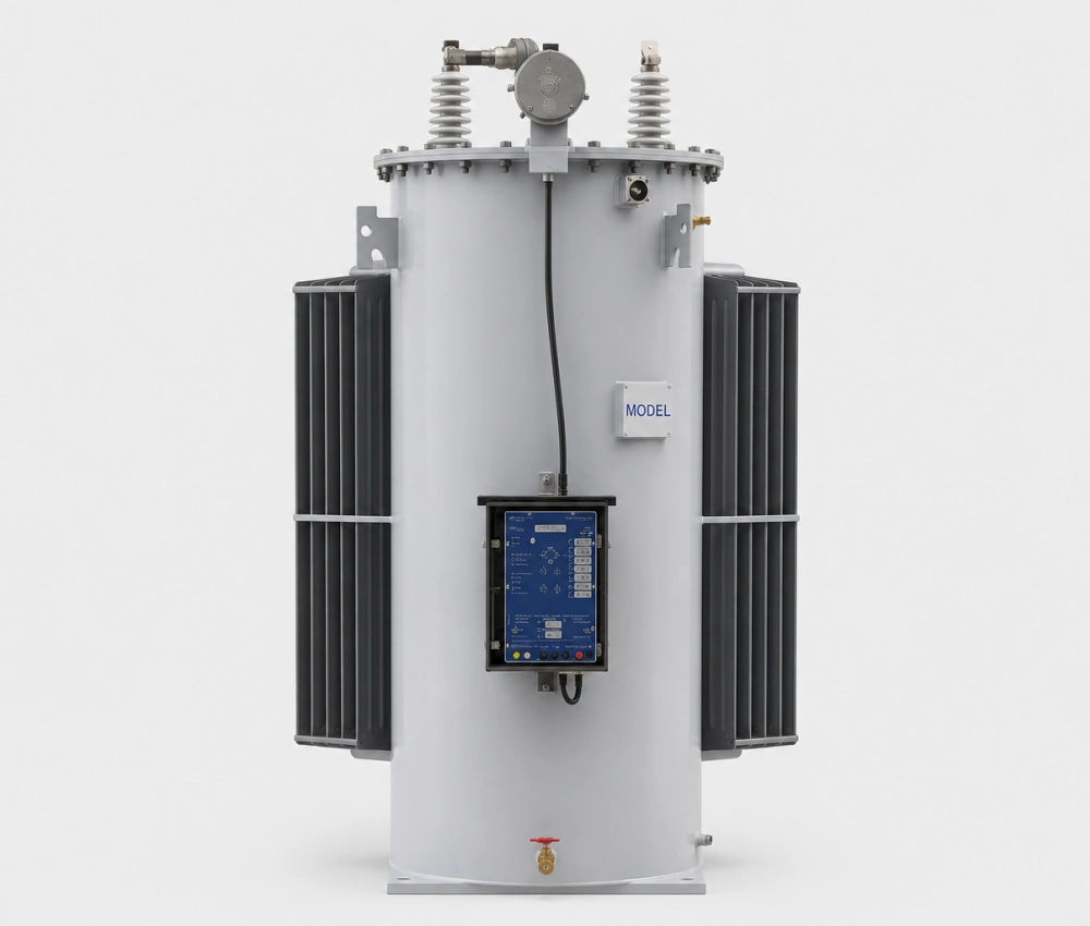
Single Phase Automatic Step Voltage Regulator
Single Phase Automatic Step Voltage Regulator Parameter
15kV,33kV Step voltage regulator Specification
Single Phase Automatic Step Voltage Regulator Technical Data
| Parameter | Specification |
| Rated Capacity | 5kVA – 100kVA |
| Input Voltage Range | 150V – 270V / 100V – 280V (customizable) |
| Output Voltage | 220V / 230V ±1% – ±3% |
| Response Time | ≤1 second |
| Efficiency | ≥98% |
| Frequency | 50/60Hz |
| Protection Functions | Over/Under voltage, overload, short circuit, surge, bypass |
| Operating Temperature | -15°C to +45°C |
| Display | LCD + LED indicators |
| Cooling Method | Natural air cooling |
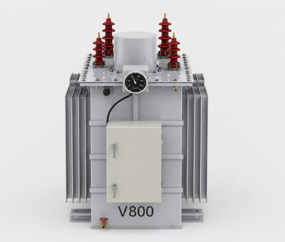
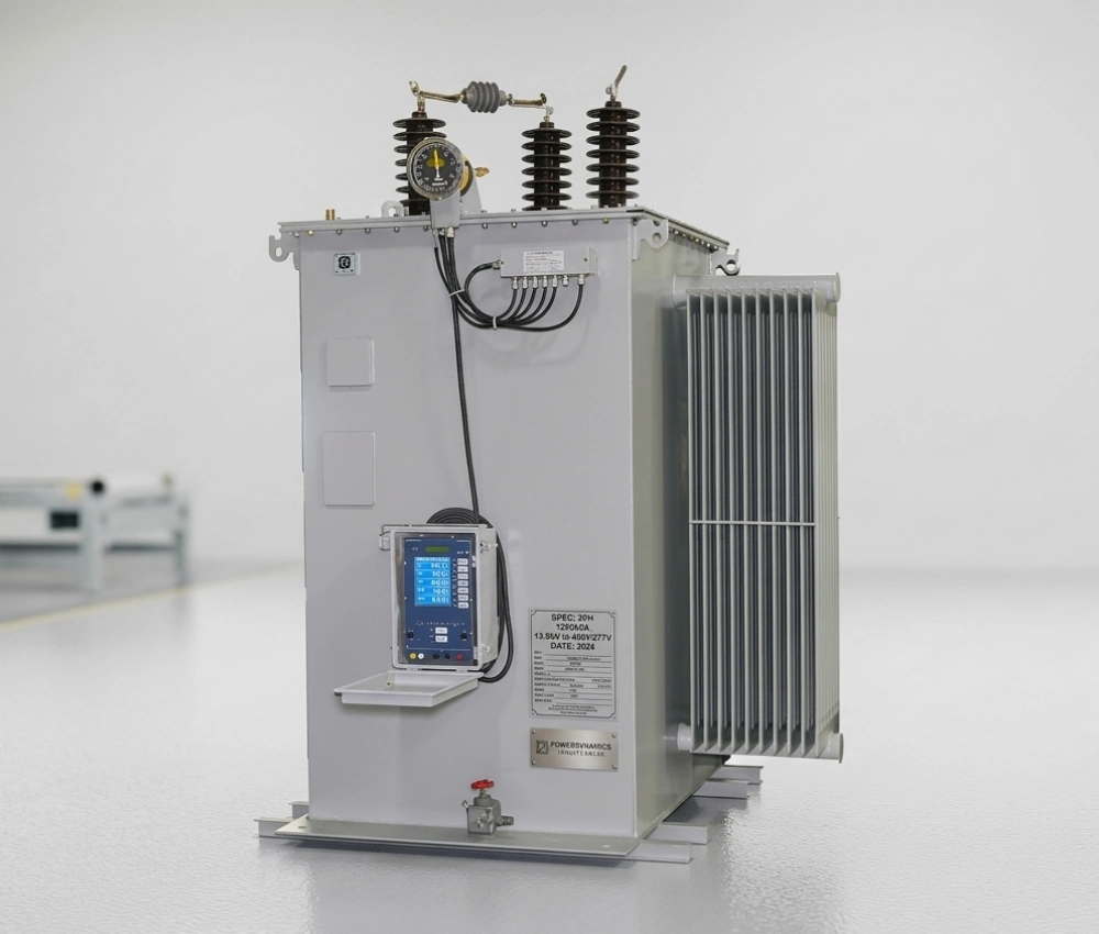
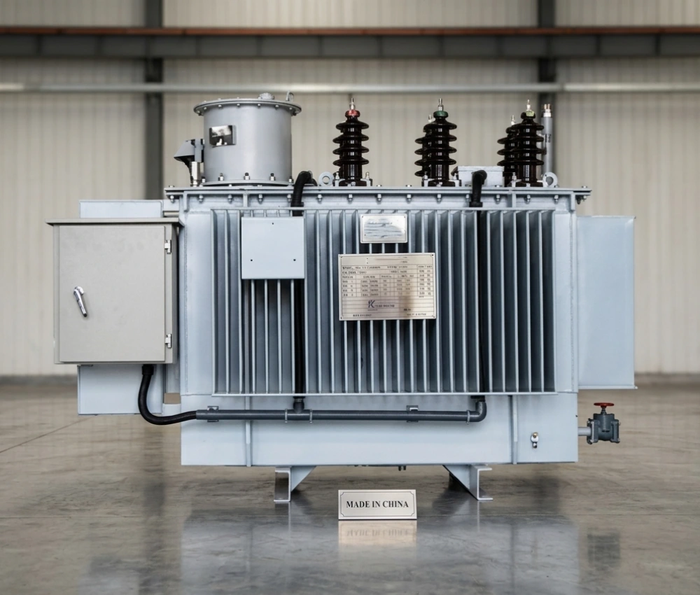
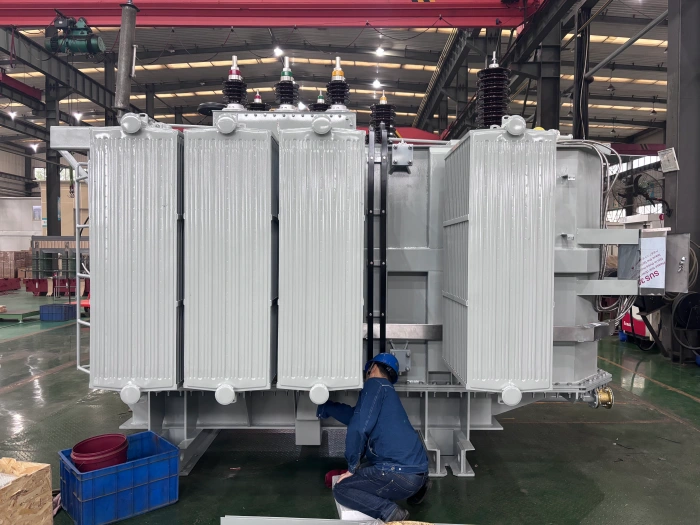
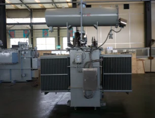
The 15kV and 33kV Step Voltage Regulator (SVR) is a single-phase, oil-immersed, pole-mounted automatic voltage regulator designed for medium voltage distribution lines. Compliant with EEU standards and IEC/IEEE requirements, it provides precise voltage stabilization with ±10% regulation in 32 steps of approximately 0.625% (5/8%) each.
Key Specifications:
- Voltage Rating: 15kV / 33kV class (50Hz)
- Regulation Range: -10% to +10%
- Capacity: 15kV series up to 600A (660kVA+); 33kV series 50-250A (165-825kVA)
- BIL: 95-200kV
- Cooling: ONAN self-cooled
- Control: Microprocessor-based automatic control with SCADA compatibility
- Features: Arc-free tap changer, fully sealed tank, maintenance-free, high-creepage bushings for tropical environments
Ideal for long feeders in Ethiopian distribution networks, these regulators reduce losses, improve power quality, and ensure stable voltage under varying loads. Equipped with pressure relief valve, oil gauges, and position indicators.
Perfect for EEU projects requiring reliable overhead line voltage regulation. Custom ratings available per tender specifications.
|
Voltage(kV)
BIL(kV)
|
Load Current
(Amperes)
|
kVA
|
|
2.5 kV
60 kV BIL
|
200
300
400
500
668
1000
1332
1665
|
50
75
100
125
167
250
333
416
|
|
5.0 kV
75 kV BIL
|
100
150
200
250
334
500
668
833
|
50
75
100
125
167
250
333
416
|
|
7.62 kV
95 kV BIL
|
100
150
219
328
438
546
656
875
1093
|
76
114
167
250
333
416
500
667
833
|
|
13.8 kV
95 kV BIL
|
100
150
200
300
400
483
604
|
138
207
276
414
552
667
833
|
|
19.92 kV
150 kV BIL
|
50
100
167
200
335
418
502
|
100
200
333
400
667
833
1000
|
|
33 kV
200 kV BIL
|
50
100
200
|
165
330
660
|
Customization Optional
Single Phase Automatic Step Voltage Regulator
Our Single-phase Automatic Step Voltage Regulator offers extensive customization to meet diverse grid conditions, load requirements, and installation environments. Customers can select input voltage ranges (e.g., 120V–260V, 140V–280V, or wider), output precision (±1%, ±2%, or ±3%), and capacity from 5kVA to 100kVA. The number of regulation steps (8–32 steps) and regulation speed can be optimized for specific applications. Advanced digital controllers with RS485/Modbus communication, Wi-Fi/GSM remote monitoring, and programmable delay times are available for smart grid integration. Enclosure options include IP20 indoor, IP54 weatherproof, or outdoor pole-mounted designs with anti-corrosion coatings. Additional features such as surge arresters, manual bypass switches, high-temperature insulation upgrades, and custom LCD interfaces with data logging ensure full adaptability to regional standards and harsh operating conditions.
For specialized needs, we provide ultra-wide input range designs for unstable rural grids, high-overload models (up to 300% momentary), low-noise configurations for hospitals and offices, and integration with backup generators or solar systems. Custom color, branding, and multi-unit parallel operation capability further enhance flexibility. These tailored solutions make our automatic step voltage regulator the preferred choice for clients searching for “custom single-phase automatic voltage regulator with high overload capacity.”
Packing and Shipping
Single Phase Automatic Step Voltage Regulator
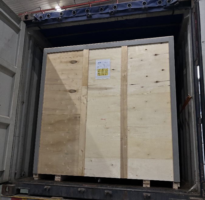
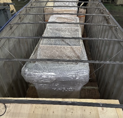
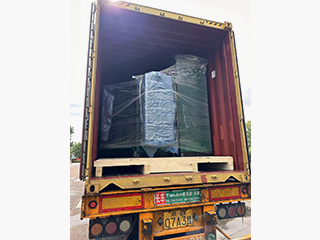
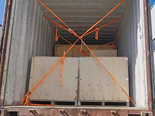
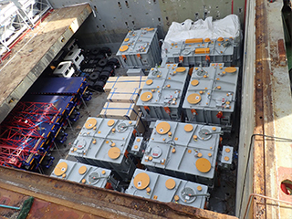
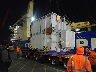
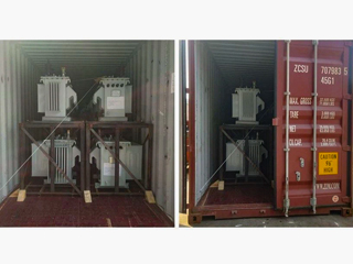
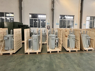
Secure packaging is critical for protecting the precision components of the Single-phase Automatic Step Voltage Regulator. Each unit is mounted on a reinforced wooden pallet with anti-vibration rubber pads and heavy-duty steel strapping to absorb shocks during transit. Sensitive electronic modules, LCD displays, and copper windings are protected with thick foam inserts and custom-molded plastic shields. The entire regulator is wrapped in multi-layer waterproof and anti-static film, with silica gel desiccants placed inside to control humidity. A sturdy, fumigated export wooden crate compliant with ISPM 15 standards fully encloses the product, reinforced with corner protectors and impact/tilt monitoring labels for complete traceability.
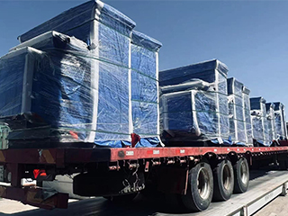
We offer flexible global shipping solutions tailored to project timelines and destinations. For international orders, sea freight in 20ft or 40ft containers ensures cost-effective and secure transport with professional blocking and bracing, typically taking 20–45 days. Air freight is available for urgent requirements, delivering within 5–10 days. Domestic and regional shipments utilize specialized trucks with GPS tracking and weatherproof tarping to guarantee safe delivery. All shipments are covered by comprehensive all-risk insurance up to the full product value.
Complete export documentation is provided, including commercial invoices, packing lists, certificates of origin, test reports, and compliance declarations to facilitate smooth customs clearance. Environmentally conscious practices such as recyclable packing materials and optimized load planning help reduce carbon footprint. Clients receive real-time tracking links and proactive updates from our dedicated logistics team.
Upon arrival, we offer optional professional unpacking guidance, on-site inspection support, and responsible disposal of packaging materials. For bulk or project orders, consolidated shipping and phased delivery options are available to minimize storage needs and project costs. This meticulous packing and shipping process ensures your automatic step voltage regulator arrives in perfect working condition, ready for immediate installation.
32
32 years of industry experience
Manufacturer Test
Single Phase Automatic Step Voltage Regulator
Progress Test
Manufacturing progress testing for the Single-phase Automatic Step Voltage Regulator begins with core material validation using Epstein frame and watt-loss testing to confirm low-loss silicon steel performance. Winding resistance and insulation strength are measured on the copper coils before assembly. Tap changer mechanism undergoes 10,000-cycle endurance testing for mechanical reliability. Initial control board calibration checks microprocessor accuracy, voltage sampling precision, and protection threshold settings. Early enclosure assembly includes IP rating verification and grounding continuity tests. These incremental checks, supported by digital traceability records, ensure foundational quality and high overload capacity during early production stages. Response time, output voltage precision, and waveform distortion are measured using precision power analyzers. Overload and short-circuit protection functions are rigorously tested at 150%–300% rated load. Thermal imaging confirms even heat distribution during continuous operation.
Design Tests
All transformer will be test after finished the production, test items as below:
♦ Insulation Power Factor
♦ Ratio, Polarity, and Phase Relation
♦ Winding Resistance
♦ Impulse Tests
♦ On load Loss Test
♦ No Load Loss Test
♦ Transformer Turns Ratio/TTR (All Tap Voltages)
♦ Impedance Voltage & Load Loss (Rated Voltage)
♦ Polarity, 1-Ph / Phase Relation, 3-Ph (Rated Voltage)
♦ Excitation & No-Load Loss (Rated Voltage)
♦ Applied Voltage
♦ Induced Voltage
♦ Lightning Impulse
♦ Insulation Resistance (Rated Voltage)
♦ Temperature Rise
♦ Dielectric Withstand (Hipot)
Factory Acceptance Test
Factory Acceptance Testing for the Single-phase Automatic Step Voltage Regulator starts with detailed input/output voltage accuracy verification across the full regulation range using calibrated voltage sources. No-load and full-load efficiency measurements confirm performance above 98%. Step switching response time and output voltage stability (±1–3%) are tested under sudden load changes. All protection functions—including over/under voltage, overload, short-circuit, and surge—are activated and validated. Control panel display accuracy, alarm functions, and communication interfaces (if equipped) are thoroughly checked. These routine electrical and functional tests, documented with waveforms and data sheets, establish baseline compliance. Advanced FAT includes extended overload testing at 150% rated capacity for 2 hours and short-time 200–300% overload simulation to verify thermal stability and automatic recovery. Harmonic distortion and power factor measurements are performed under different load types.
Routine Test - Impulse Tests
Purpose of Testing
The purpose of Impulse Tests is to verify the insulation strength of electrical equipment when it is subjected to lightning strikes or switching overvoltages. By applying high-energy impulse voltages, it is possible to detect potential defects in the insulation system.
Testing Equipment
Impulse voltage generator (e.g. Haefely, Hipotronics, Tettex, etc.)
Voltage divider (used to measure impulse voltage waveform, resistor divider or capacitor divider)
Oscilloscope (used to record impulse waveform, common brands such as Tektronix, Keysight)
Voltage divider (used to measure impulse voltage waveform, resistor divider or capacitor divider)
Oscilloscope (used to record impulse waveform, common brands such as Tektronix, Keysight)
Pre-Test Preparation
Please test under suitable environmental conditions: relative humidity less than 65%, no rain or condensation (recommended temperature: 15-30°C).
Calibrate and check the impulse voltage generator, measurement system, and control system to ensure that the instruments and equipment are in good condition and meet the test standards.
Calibrate and check the impulse voltage generator, measurement system, and control system to ensure that the instruments and equipment are in good condition and meet the test standards.
Test Progress
Connect the Test Instrument:
Connect the impulse voltage generator correctly to each winding terminal (high voltage terminal, ground terminal) of the device under test, and ensure that all test instruments are well grounded.
Apply Test Voltage:
Select the appropriate impulse voltage waveform and amplitude according to the rated voltage of the equipment
Measure and Record
Collect and record the impact waveform, including:
Front Time
Time to Half-Value
Peak Voltage
Distortion
Ambient temperature and humidity (especially when the test environment needs to be corrected)
Front Time
Time to Half-Value
Peak Voltage
Distortion
Ambient temperature and humidity (especially when the test environment needs to be corrected)
Waveform Correction
Check whether the impulse voltage waveform meets the specification requirements (wave head time 1.2μs ±30%, half-peak time 50μs ±20%).
If the waveform deviation is too large, adjust the impulse generator parameters and reapply the test.
If the waveform deviation is too large, adjust the impulse generator parameters and reapply the test.
Repeat Testing (if necessary)
Impact tests are performed for different phases and windings (HV/MV/LV).
In special cases, inter-winding impact, voltage-to-ground impact or coil corner impact are performed (according to the test plan).
In special cases, inter-winding impact, voltage-to-ground impact or coil corner impact are performed (according to the test plan).
Evaluation Criteria (Reference)
No internal insulation breakdown or flashover (detected by observing waveform continuity and audibly).
Waveforms are stable and meet standard specifications.
Waveform variations between repeated tests are minimal (usually good waveform overlap with no noticeable abnormal excursions).
Waveforms are stable and meet standard specifications.
Waveform variations between repeated tests are minimal (usually good waveform overlap with no noticeable abnormal excursions).
*These comprehensive tests ensure that each transformer meets performance standards and operates
reliably under various conditions.
Application
Ideal for small commercial shops, offices, medical clinics, and light industrial workshops, protecting sensitive equipment such as computers, servers, and CNC machines from voltage fluctuations.


Technical Advantages
● 30+ years of manufacturing experience
● ISO and UL certified production
● Customized cable and transformer solutions


Product Packaging
Transformers Packaging (1)
Transformers Packaging (2)
Transformers Packaging (3)
Transformers Packaging (4)
Transformers Packaging (5)
Transformers Packaging (6)
Transformers Packaging (7)
Transformers Packaging (8)
Related Products
40MVA 110kV Three Phase Oil Immersed Transformer for Substation
The 40MVA 110kV Three Phase Oil Immersed Transformer is engineered for reliable high-voltage transmission and distribution in substations and power plants. Featuring high-purity copper windings, advanced ONAN/ONAF cooling, and on-load tap changer (OLTC ±8×1.25%), it delivers superior efficiency and minimal no-load/loss performance (SZ11/SZ13 series). Fully compliant with IEC 60076, GB 6451, and IEEE standards, it withstands 200kV lightning impulse and offers partial discharge below 10pC. The corrugated tank design ensures optimal heat dissipation and mechanical strength in harsh environments. Ideal for 110/33kV, 110/11kV, or 110/6.3kV step-down applications. Vacuum oil filling and nitrogen sealing guarantee long-term insulation integrity. Trusted by utilities worldwide for stable, maintenance-free operation over 30+ years. Contact us for technical datasheet and competitive pricing.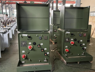
33kV Single Phase Pole Mounted Transformer
Designed for medium-voltage overhead systems, the 33kV single phase pole mounted transformer efficiently steps down primary voltages of 33kV (or 34.5kV variants) to secondary levels such as 230V, 240V, or 415V, serving substantial single-phase loads in extended networks. Constructed with advanced grain-oriented silicon steel cores and precision windings, it achieves minimal no-load and load losses while fully complying with IEC 60076 and IEEE C57 requirements. The oil-immersed tank with ONAN cooling maintains a 65°C temperature rise, supporting reliable performance during peak demands and harsh weather exposure. High insulation levels, including 150-200kV BIL on the HV side, combined with pressure relief valves, HV bushings with arcing horns, and optional surge arresters, provide exceptional protection against lightning and overvoltages. This transformer offers quiet operation, strong overload capacity, and extended service life, making it essential for utilities optimizing power access in remote or growing areas.
2000kVA Three Phase Pad Mounted Transformer
2000kVA Three Phase Pad Mounted transformer adopts a fully sealed oil-immersed design, which complies with international standards such as IEC, ANSI and GB. It has the characteristics of high efficiency, low loss and strong weather resistance. It is widely used in industrial parks, commercial complexes, power companies and new energy projects, and is particularly suitable for medium and large load environments that require both stable power supply and energy saving.
500kVA Three Phase Pad Mounted Transformer
The 500kVA three-phase pad transformer is an efficient and sturdy power equipment designed for commercial, industrial and distribution systems. It has a compact design and a protective casing that meets NEMA 3R or higher standards. It is suitable for various outdoor environments and can effectively resist external factors such as weather, dust and moisture. It can meet the power needs of different regions and has a variety of optional functions, such as load regulation and temperature control systems, to further improve its operating efficiency and safety. The built-in protection device can effectively prevent overload, short circuit and other faults to ensure the safe and reliable operation of the power system.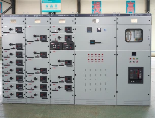
Armored Removable AC Switchgear
The Armored Removable AC Switchgear is a high-performance medium-voltage electrical distribution system specifically engineered for industrial power networks, utility substations, commercial infrastructure, and smart-grid applications. The switchgear adopts a metal-clad armored structure combined with a removable withdrawable unit design, integrating vacuum circuit breakers, protection relays, busbar systems, metering devices, and intelligent control components into a compact modular cabinet configuration. This advanced structure significantly improves operational safety, maintenance efficiency, and system reliability for modern electrical distribution environments. Designed according to international medium-voltage distribution standards, the armored removable AC switchgear provides excellent insulation performance, internal arc resistance, and mechanical durability under demanding operating conditions. The withdrawable breaker mechanism allows convenient maintenance and rapid replacement while reducing operational downtime and improving personnel safety during inspection procedures. The compartmentalized enclosure design effectively isolates busbar sections, cable chambers, breaker compartments, and control circuits to minimize fault propagation risks and enhance overall system protection. The Armored Removable AC Switchgear supports intelligent monitoring systems, remote communication protocols, and automated protection functions for modern digital substations and smart-grid infrastructure. With flexible configuration capabilities and scalable electrical distribution architecture, the system delivers dependable medium-voltage switching and protection performance for industrial automation systems, renewable energy projects, utility power networks, transportation infrastructure, and mission-critical electrical facilities.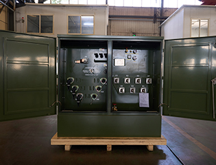
250kVA Three Phase Pad Mounted Transformer
The 250kVA Three Phase Pad Mounted Transformer is a compact, liquid-immersed, self-cooled (ONAN) distribution transformer optimized for efficient, underground power delivery in residential, light commercial, and small industrial applications. Fully compliant with IEEE C57.12.34, ANSI C57.12.00, DOE 2016 efficiency standards, and UL-listed, this compartmental-type unit features dead-front 200A high-voltage bushing wells (loadbreak inserts), radial or loop feed options, and a sealed tank using non-PCB mineral oil or FR3 natural ester fluid for improved fire safety and environmental performance.FAQ From Customers
-
What is a Transformer?A transformer is an electrical device used to change the voltage of alternating current (AC). It works on the principle of electromagnetic induction, converting high-voltage current into low-voltage current or low-voltage current into high-voltage current. Transformers are widely used in power transmission, distribution systems, and various electronic devices.
-
What are the main uses of a transformer?The main use of a transformer is voltage conversion. Transformers are used in power transmission systems to help transfer electricity from power plants to consumers. In addition, transformers are also used in electronic devices such as chargers, televisions, power adapters, etc., to adjust the voltage to meet the requirements of different devices.
-
Do you have UL listed?Yes, our transformer has UL listed. We have exported to America many pad mounted transformer,substation transformer and HV.
Welcome your inquiry
Honesty, Integrity, Frugality, Activeness and Passion