BESS Transformer Guide: Design, Sizing and Selection for Energy Storage Plants
2026-03-17
The rapid expansion of renewable energy has significantly increased the demand for efficient energy storage solutions. Technologies such as battery energy storage systems (BESS) play a critical role in stabilizing the power grid, improving grid flexibility, and enabling higher integration of solar and wind energy.
At the center of every energy storage system is a critical component known as the BESS transformer. This transformer connects the energy storage plant to the electrical grid and ensures proper voltage matching between the battery modules, power conversion systems (PCS), and the grid voltage.
BESS transformers are widely used in:
- Solar energy battery storage plants
- Wind energy storage systems
- Utility-scale battery energy storage systems (BESS)
- Industrial microgrids
What is a BESS Transformer?
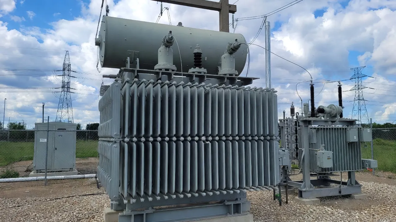
A BESS Transformer (Battery Energy Storage System Transformer), also known as a BESS step-up transformer or energy storage transformer, is a critical piece of power equipment in Battery Energy Storage Systems (BESS). It converts low-voltage AC power from inverters into medium- or high-voltage suitable for grid connection, while providing electrical isolation and system protection. In a BESS, lithium-ion batteries store excess energy (from solar, wind, or off-peak grid power) as DC electricity. The Power Conversion System (PCS) or bidirectional inverter then converts DC to low-voltage AC (typically 0.4kV–0.69kV). However, most power grids require higher voltages (such as 10kV, 35kV, 138kV, or more). The BESS Transformer steps up this voltage efficiently, enabling safe and low-loss integration with the grid. It also handles bidirectional power flow during charging and discharging.
Beyond voltage conversion, it offers electrical isolation to prevent faults from spreading, suppresses harmonics generated by inverters (which can cause overheating), mitigates overvoltages, DC bias, and saturation risks, and maintains a stable power factor under rapid charge/discharge cycles.
Key Features and Types
The transformer performs several essential functions:
- Voltage conversion between PCS and the grid
- Electrical isolation
- Power flow management
- Grid stability support
BESS Transformer Definition
|
Term |
Description |
|
BESS Transformer |
Transformer connecting battery storage systems to grid |
|
Technology that stores electricity for later use |
|
|
Battery Modules |
Battery units storing electrical energy |
|
Power Conversion System |
Converts DC power from batteries to AC |
In most energy storage systems, batteries store energy in DC form, while the power grid operates in AC. Therefore, a transformer works with the PCS inverter system to deliver electricity to the grid.
Role of BESS in Modern Power Systems
Energy storage systems are becoming a key component of modern power grids, especially as renewable energy production increases.
Key Applications of Energy Storage Systems
|
Application |
Description |
|
Frequency regulation |
Stabilizes grid frequency |
|
Peak shaving |
Reduces demand during peak load |
|
Renewable energy integration |
Stores excess solar and wind energy |
|
Backup power supply |
Provides power during outages |
For example, solar energy storage systems allow utilities to store excess solar generation during the day and release it at night.
BESS Transformer System Design
The system design of a BESS transformer depends on several engineering parameters.
Key Design Considerations
|
Design Factor |
Importance |
|
Grid voltage |
Determines transformer voltage rating |
|
Power capacity |
Defines transformer size |
|
Battery module configuration |
Affects PCS output |
|
Cooling system |
Ensures thermal stability |
|
Harmonic performance |
Improves grid power quality |
Most energy storage plants use medium voltage transformers to connect PCS systems to the utility grid.
BESS Transformer Loss Calculation
Transformer efficiency is extremely important in large-scale energy storage systems because energy may pass through the transformer multiple times during charging and discharging cycles.
Transformer Loss Types
|
Loss Type |
Description |
|
No-load loss |
Core loss when the transformer is energized |
|
Load loss |
Copper loss in transformer windings |
|
Stray loss |
Leakage magnetic field losses |
|
Auxiliary loss |
Cooling fan or pump consumption |
Simplified Efficiency Formula
Efficiency (%) = Output Power / (Output Power + Total Losses) × 100Typical Loss Values
|
Transformer Size |
No Load Loss |
Load Loss |
|
5 MVA |
4 kW |
35 kW |
|
10 MVA |
7 kW |
65 kW |
|
25 MVA |
15 kW |
150 kW |
|
50 MVA |
28 kW |
300 kW |
High-efficiency transformers can reduce losses by 20–30%, improving the overall economics of solar energy storage systems.
Typical BESS Transformer Configuration
Energy storage plants often use a step-up transformer configuration.
BESS Power Flow Architecture
|
Component |
Function |
|
Battery modules |
Store electrical energy |
|
Battery management system |
Controls battery operation |
|
Power conversion system (PCS) |
Converts DC to AC |
|
BESS transformer |
Matches the PCS voltage to the grid voltage |
|
Grid connection |
Transfers power to the grid |
This architecture allows the energy storage system to store energy during low-demand periods and deliver electricity when demand increases.
BESS Transformer Capacity Chart (1MVA–200MVA)
When designing a battery energy storage system (BESS), transformer capacity must match the power capacity of the PCS and total battery modules. Below is a practical reference chart used by engineers when designing energy storage plants connected to medium or high-voltage grids.
BESS Transformer Capacity Reference Table
|
Energy Storage Plant Size |
PCS Power Capacity |
Recommended BESS Transformer |
|
Small commercial BESS |
1 MW |
1.25 MVA |
|
Industrial BESS |
5 MW |
6.3 MVA |
|
Utility-scale BESS |
10 MW |
12.5 MVA |
|
Solar + storage plant |
20 MW |
25 MVA |
|
Large wind storage system |
50 MW |
63 MVA |
|
Utility grid storage |
100 MW |
125 MVA |
|
Mega storage facility |
150 MW |
160 MVA |
|
Large grid stabilization BESS |
200 MW |
200 MVA |
Engineering Note
A safety margin of 10–25% above PCS power capacity is commonly used in energy storage system design to account for:
- Harmonics generated by power electronics
- Overload during frequency regulation
- Thermal stress during peak shaving
Voltage Levels in Energy Storage Plants
The grid voltage determines the transformer configuration.
Typical Voltage Levels
|
System Type |
Voltage Range |
|
PCS output |
400V – 690V |
|
Medium voltage collection system |
10kV – 35kV |
|
Utility grid connection |
35kV – 110kV |
The BESS transformer typically performs low voltage to medium-voltage step-up transformation.
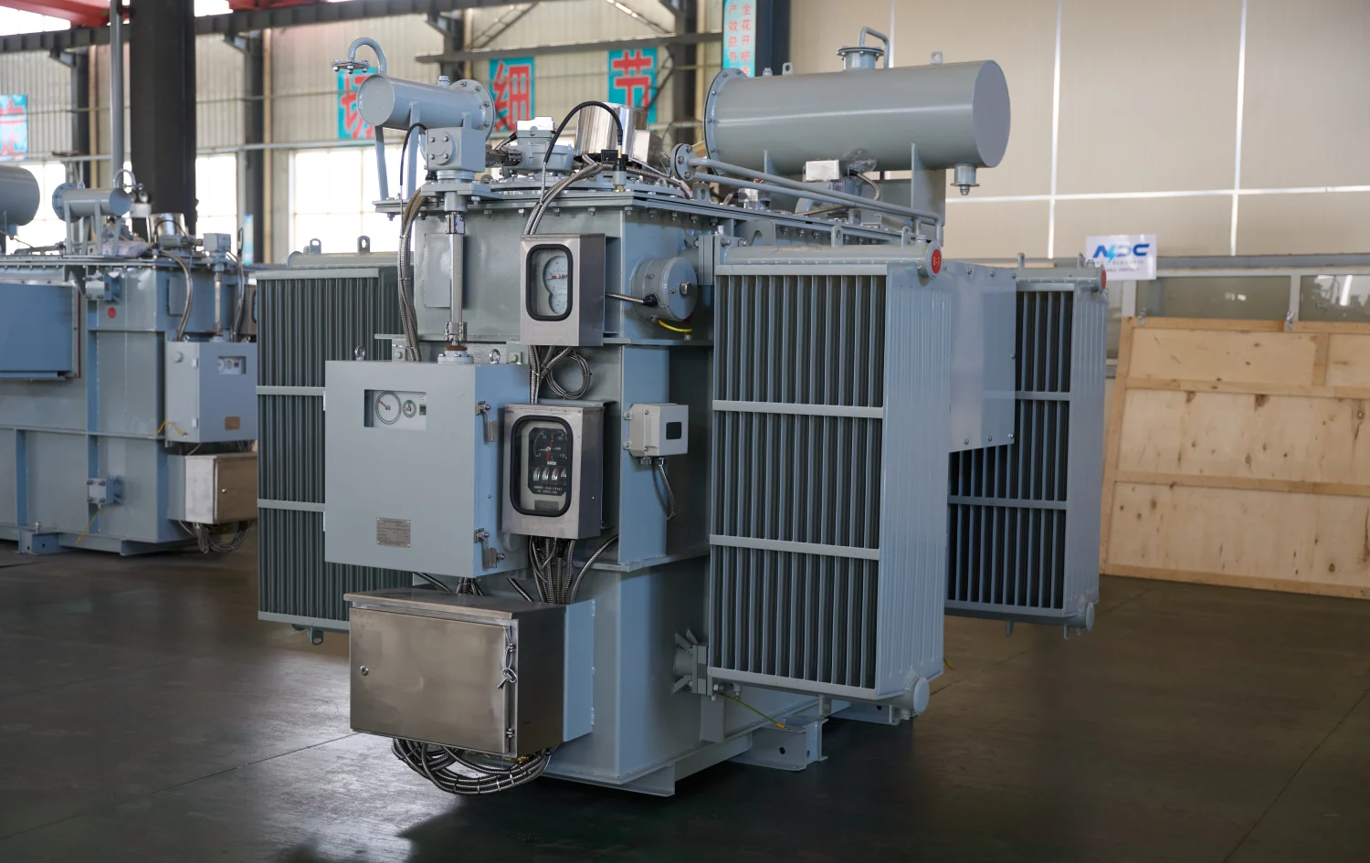
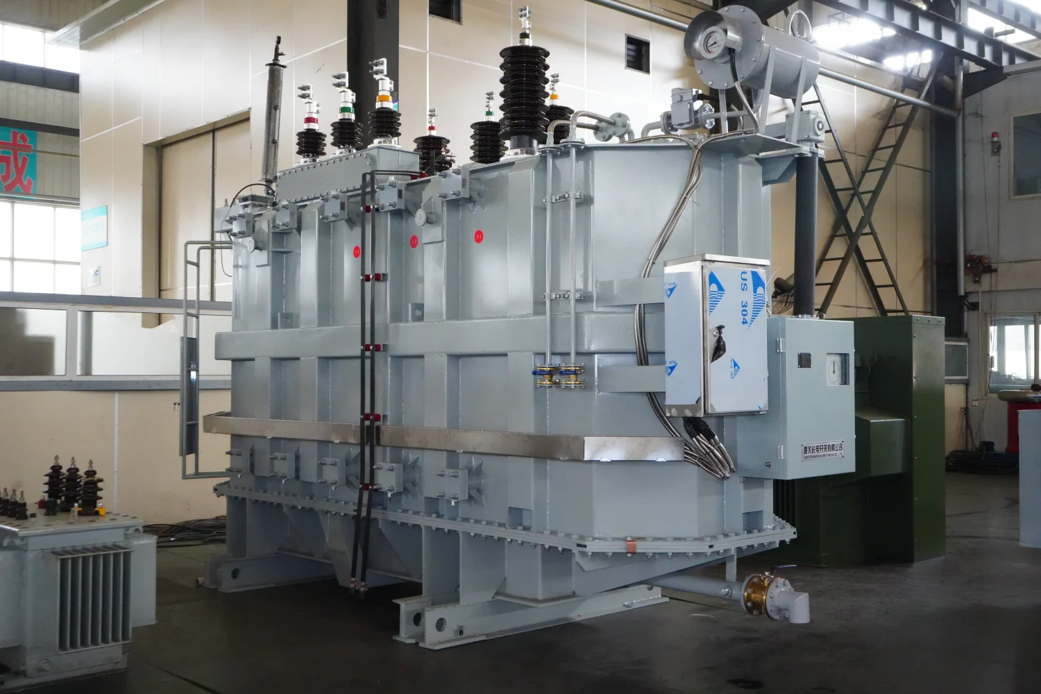
BESS Transformer Cooling Methods
Energy storage systems often operate continuously, making cooling systems critical.
Cooling Methods
|
Cooling Type |
Description |
|
ONAN |
Oil Natural Air Natural |
|
ONAF |
Oil Natural Air Forced |
|
Dry-type cooling |
Air cooled transformers |
Large-scale energy storage systems BESS often use oil-immersed transformers because of their high thermal capacity.
Integration with Renewable Energy
Energy storage systems are increasingly integrated with solar and wind energy plants.
Renewable Energy + BESS
|
Energy Source |
Role of Storage |
|
Solar energy |
Store excess daytime generation |
|
Wind power |
Smooth intermittent output |
|
Natural gas backup |
Reduce fuel consumption |
This integration improves grid reliability and reduces dependence on fossil fuels such as natural gas.
BESS Transformer vs Solar Transformer (PV + Storage Systems)
With the rapid growth of solar energy storage systems, many renewable energy plants now combine photovoltaic (PV) generation with battery energy storage systems (BESS). In these hybrid plants, two types of transformers are commonly used: solar transformers and BESS transformers.
Although both transformers operate within renewable energy infrastructures, their design objectives, operational characteristics, and electrical requirements are different.
Understanding these differences is essential for engineering system design, equipment selection, and grid integration.
Role in Renewable Energy Plants
In a PV + Storage hybrid power plant, transformers serve different stages of the power flow process.
|
Transformer Type |
Primary Role |
System Position |
|
Steps up voltage from solar inverters |
Between PV inverter and grid |
|
|
BESS Transformer |
Connects battery storage to grid |
Between PCS and grid |
In practical projects, the solar system generates electricity during the day while the battery energy storage system stores excess energy for later use.
Operational Characteristics
Solar power generation follows the sunlight cycle, while BESS systems operate based on grid demand and energy management strategies.
|
Parameter |
BESS Transformer |
Solar Transformer |
|
Power flow |
Bidirectional |
Mostly unidirectional |
|
Operating cycle |
Continuous charge/discharge |
Daytime solar generation |
|
Grid support |
Frequency regulation |
Power injection |
|
Load variation |
High |
Moderate |
Because of frequent charging and discharging cycles, BESS transformers must withstand more dynamic load conditions than typical solar transformers.
Electrical Design Differences
Although both transformers operate in renewable energy plants, their electrical design parameters differ.
|
Parameter |
BESS Transformer |
Solar Transformer |
|
Input source |
Battery modules via PCS |
Solar inverter output |
|
Harmonic level |
Higher due to power electronics |
Moderate |
|
Thermal stress |
High |
Medium |
|
Efficiency focus |
Long-term cycling efficiency |
Peak generation efficiency |
The presence of power electronics in both systems means that transformer designs must consider harmonic currents and voltage distortion.
Typical Voltage Configurations
Voltage configurations in PV + storage systems depend on the scale of the power plant.
|
System Component |
Typical Voltage |
|
Solar inverter output |
400V – 800V |
|
Battery PCS output |
400V – 690V |
|
Medium voltage collection system |
10kV – 35kV |
|
Grid interconnection |
35kV – 110kV |
Both solar transformers and BESS transformers typically perform low-voltage to medium-voltage step-up transformation.
Hybrid Solar + Storage System Architecture
A typical solar energy storage system combines photovoltaic generation with battery storage to improve grid flexibility.
Simplified Energy Flow
Solar Panels
     ↓
Solar Inverter
     ↓
Solar Transformer
     ↓
Medium Voltage Collection Grid
     ↓
Power Grid
Storage Energy Flow
Battery Modules
     ↓
Power Conversion System (PCS)
     ↓
BESS Transformer
     ↓
Medium Voltage Grid
This architecture enables renewable energy plants to:
- store excess solar energy
- perform peak shaving
- provide frequency regulation
- Stabilize the power grid
Engineering Selection Considerations
When designing PV + BESS hybrid power plants, engineers must evaluate several transformer selection factors:
|
Selection Factor |
Importance |
|
Power capacity |
Match solar or storage plant capacity |
|
Grid voltage |
Determine transformer rating |
|
Cooling method |
Support continuous operation |
|
Harmonic tolerance |
Handle inverter-generated harmonics |
|
Reliability |
Ensure long-term renewable plant operation |
In many modern solar plants, both solar transformers and BESS transformers operate together to provide flexible renewable energy generation and storage.
Summary
While both BESS transformers and solar transformers support renewable energy systems, they serve different operational purposes.
- Solar transformers connect photovoltaic inverters to the grid.
- BESS transformers connect battery storage systems to the grid and support bidirectional power flow.
Together, these transformers enable modern solar energy storage systems to store energy, stabilize the grid, and maximize renewable power utilization.
BESS Transformer Selection Guide
Choosing the right BESS transformer requires evaluating several engineering factors.
Selection Criteria
|
Factor |
Explanation |
|
Power capacity |
Must match PCS output |
|
Voltage rating |
Must match grid connection |
|
Cooling system |
Required for continuous operation |
|
Efficiency |
Reduces energy losses |
|
Harmonic performance |
Ensures grid compatibility |
Selecting the correct transformer ensures long-term reliability of the energy storage system.
BESS Transformer vs Power Transformer vs Distribution Transformer
Transformers used in modern power systems serve different roles depending on their location in the electrical network. In energy storage plants, BESS transformers are specifically engineered to connect battery storage systems to the grid. However, they are often compared with power transformers and distribution transformers, which serve different functions in the transmission and distribution infrastructure.
Understanding these differences helps engineers choose the correct transformer type for renewable energy projects, grid interconnection systems, and industrial power facilities.
Functional Differences
The three transformer types operate at different levels of the electrical network and handle different power capacities.
|
Transformer Type |
Main Function |
Typical Location |
|
BESS Transformer |
Connects battery energy storage systems to the grid |
Energy storage plants |
|
Transfers bulk electrical power at the transmission level |
Transmission substations |
|
|
Steps voltage down for end users |
Distribution networks |
In energy storage projects, the BESS transformer acts as the interface between the power conversion system (PCS) and the medium-voltage grid.
Voltage Level Comparison
One of the most important technical differences between these transformers is the voltage range they operate in.
|
Transformer Type |
Typical Voltage Range |
Application |
|
BESS Transformer |
0.4kV – 35kV |
Energy storage plants |
|
Power Transformer |
110kV – 800kV |
Transmission networks |
|
Distribution Transformer |
0.4kV – 35kV |
Local power distribution |
While power transformers operate at extremely high voltage levels, BESS transformers are typically designed for medium voltage grid integration.
Power Capacity Comparison
Another key difference is power capacity, which reflects the scale of each transformer type.
|
Transformer Type |
Capacity Range |
|
BESS Transformer |
1 MVA – 200 MVA |
|
Power Transformer |
100 MVA – 1000+ MVA |
|
Distribution Transformer |
10 kVA – 10 MVA |
Large utility-scale energy storage systems often require transformers between 10 MVA and 100 MVA, depending on the project size.
Operational Characteristics
Because energy storage systems operate differently from traditional power networks, BESS transformers have unique operating requirements.
|
Parameter |
BESS Transformer |
Power Transformer |
Distribution Transformer |
|
Power flow |
Bidirectional |
Mostly unidirectional |
Unidirectional |
|
Load variation |
High |
Moderate |
Low |
|
Harmonic tolerance |
High |
Moderate |
Low |
|
Cooling requirement |
High |
High |
Moderate |
|
Application |
Energy storage plants |
Transmission grids |
Local power supply |
The bidirectional power flow requirement is the most distinctive feature of BESS transformers, as batteries must both store energy and deliver electricity to the grid.
Application Scenarios
Each transformer type serves a unique purpose in the electrical infrastructure.
|
Transformer Type |
Typical Applications |
|
BESS Transformer |
Solar energy storage plants, wind storage systems, grid frequency regulation |
|
Power Transformer |
Long-distance power transmission between generating stations and substations |
|
Distribution Transformer |
Power supply for residential, commercial, and industrial consumers |
For example, in a solar energy battery storage project, the system may include:
- Solar inverter transformers
- BESS transformers
- distribution transformers for auxiliary power
Together, these components ensure stable and efficient energy flow throughout the power grid.
Engineering Selection Guidelines
When selecting transformers for renewable energy projects, engineers must evaluate:
- Power capacity of the system
- Grid voltage level
- Energy storage plant size
- Cooling and efficiency requirements
- Long-term operating conditions
In large renewable energy plants, the combination of power transformers, distribution transformers, and BESS transformers forms a complete electrical infrastructure that supports reliable grid operation.
Summary
Although BESS transformers, power transformers, and distribution transformers all perform voltage conversion, their roles in the electrical power system are fundamentally different.
- BESS transformers connect battery energy storage systems to the grid
- Power transformers transfer large amounts of electricity across high-voltage transmission networks
- Distribution transformers deliver electricity to end users
As renewable energy adoption increases worldwide, BESS transformers are becoming a critical component in modern energy infrastructure, enabling energy storage systems to stabilize the grid and support sustainable power generation.
Advantages of BESS Energy Storage Solutions
Modern energy storage solutions provide numerous benefits for power systems.
Key Advantages
|
Advantage |
Description |
|
Grid stability |
Supports frequency regulation |
|
Renewable integration |
Enables higher solar penetration |
|
Peak shaving |
Reduces peak demand |
|
Energy arbitrage |
Store energy when cheap and sell when it is expensive |
These benefits make battery energy storage systems essential for future power grids.
Future Trends in BESS Transformer Technology
As global energy demand grows, the role of battery energy storage systems will expand significantly.
Emerging trends include:
- Larger utility-scale BESS plants
- Smart transformer monitoring systems
- Higher efficiency transformer cores
- Integration with smart grids
Advanced transformer technologies will help ensure efficient and reliable energy storage infrastructure.
Battery Energy Storage System Layout (Engineering Overview)
A typical utility-scale battery energy storage system includes multiple subsystems working together to deliver electricity to the grid.
BESS Plant Architecture
|
System Component |
Function |
|
Battery modules |
Store electrical energy |
|
Battery management system |
Monitors battery performance |
|
Power conversion system |
Converts DC to AC |
|
BESS transformer |
Matches PCS voltage to grid voltage |
|
Medium voltage switchgear |
Controls grid connection |
|
Energy management system |
Controls plant operation |
Typical Energy Flow
Battery Modules (DC)
      ↓
Power Conversion System (PCS)
      ↓
BESS Transformer
      ↓
Medium Voltage Grid
      ↓
Power Grid / Renewable Energy Network
This architecture allows energy storage systems to:
- store energy from solar or wind
- support grid voltage stability
- provide frequency regulation
- perform peak shaving
A BESS transformer is a critical component in modern battery energy storage systems, enabling efficient integration between battery modules, power conversion systems, and the power grid.
By properly designing, sizing, and selecting transformers, engineers can ensure that energy storage plants operate safely, efficiently, and reliably.
As renewable energy continues to grow worldwide, energy storage solutions combined with advanced transformer technology will play a central role in supporting the future of sustainable power systems.
FAQ Section
Why are transformers needed in battery energy storage systems?
Transformers match the voltage output of the PCS inverter to the required grid voltage, enabling efficient power transmission.
What transformer is used in energy storage plants?
Most large energy storage systems use medium voltage oil-filled transformers ranging from 5 MVA to 200 MVA, depending on plant capacity.
Can BESS transformers handle bidirectional power flow?
Yes. BESS transformers are designed to support bidirectional power flow, allowing the system to both store energy and deliver electricity to the grid.
What is the typical voltage of a BESS transformer?
Typical voltage levels include:
- 690V / 10kV
- 690V / 33kV
- 0.8kV / 35kV
Depending on the energy storage plant design.
Related Articles


Related Products
FG7H1OAR - 3.6/6kV, 6/10kV, 8.7/15kV and 12/20kV Cable
The FG7H1OAR - 3.6/6kV, 6/10kV, 8.7/15kV and 12/20kV Cable is a high-quality medium-voltage power cable designed for reliable fixed installations in demanding environments. It features stranded copper or aluminum conductors (class 2), semi-conductive conductor screen, XLPE (cross-linked polyethylene) insulation for excellent dielectric strength and thermal stability (90°C continuous, 250°C short-circuit), semi-conductive insulation screen, copper tape or wire screen for grounding and protection, optional armor (steel tape/wire), and a robust PVC or PE outer sheath resistant to mechanical stress, oils, chemicals, and UV. Compliant with IEC 60502-2 and equivalent standards (e.g., VDE, national codes), it offers low capacitance, high current-carrying capacity, and long service life. Available in single-core or multi-core configurations, the FG7H1OAR is ideal for power distribution in industrial plants, mining facilities, substations, and underground networks where safety, durability, and performance are critical.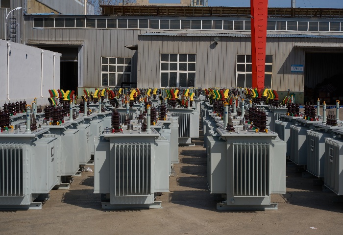
11kV Oil Immersed Transformer
The 11kV Oil Immersed Transformer is a robust, three-phase medium-voltage distribution unit optimized for efficient step-down power delivery in 50/60Hz AC networks. Engineered with a hermetically sealed tank featuring corrugated fins for thermal expansion compensation, it eliminates conservator requirements while offering superior moisture protection and extended operational durability. High-grade cold-rolled grain-oriented silicon steel laminations reduce core losses significantly, paired with low-resistance copper or aluminum windings for minimized load losses and enhanced conductivity.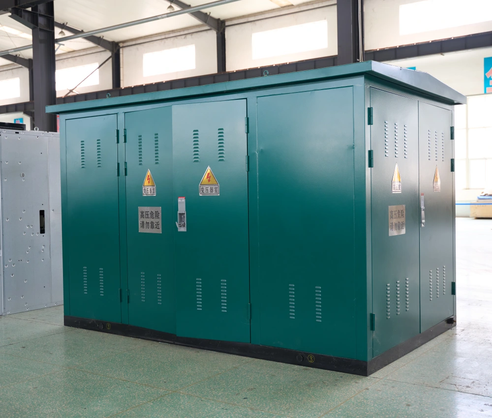
22kV 1000kVA Prefabricated Compact Substation
The 22kV 1000kVA Prefabricated Compact Substation is a modern integrated power distribution solution designed for medium-voltage electrical networks requiring high operational reliability, compact installation, and efficient energy transformation. The system integrates 22kV medium-voltage switchgear, a 1000kVA distribution transformer, low-voltage distribution equipment, and intelligent control devices into a single modular enclosure, significantly reducing installation complexity and project construction time. Manufactured using high-strength corrosion-resistant materials and advanced electrical insulation technology, the compact substation is engineered for stable outdoor operation under demanding environmental conditions. Its optimized structural layout improves heat dissipation efficiency, maintenance accessibility, and operational safety while minimizing installation footprint for urban infrastructure and industrial applications. The 22kV 1000kVA compact transformer substation is widely suitable for renewable energy systems, industrial production facilities, mining operations, commercial complexes, municipal distribution networks, and smart-grid infrastructure projects. With intelligent communication capability and flexible configuration options, the substation delivers reliable, energy-efficient, and scalable medium-voltage power distribution performance.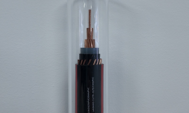
4/0 AWG Aluminum URD Cable 1/3 Neutral
The 4/0 AWG Aluminum URD Cable 1/3 Neutral is a durable and economical 600V underground residential distribution cable engineered for service entrance and secondary power delivery. It utilizes a 4/0 AWG stranded AA8000 aluminum alloy phase conductor with XLPE insulation and a 1/3 concentric aluminum alloy neutral, all protected by a rugged black polyethylene sheath. This design offers excellent flexibility, high conductivity, and superior moisture resistance, making it suitable for direct burial or conduit installations. The 1/3 neutral configuration provides a balanced and cost-effective solution for most residential applications. Manufactured to UL 854 and ICEA standards, the 4/0 AWG Aluminum URD Cable 1/3 Neutral undergoes extensive quality testing to ensure consistent performance and long service life in underground environments.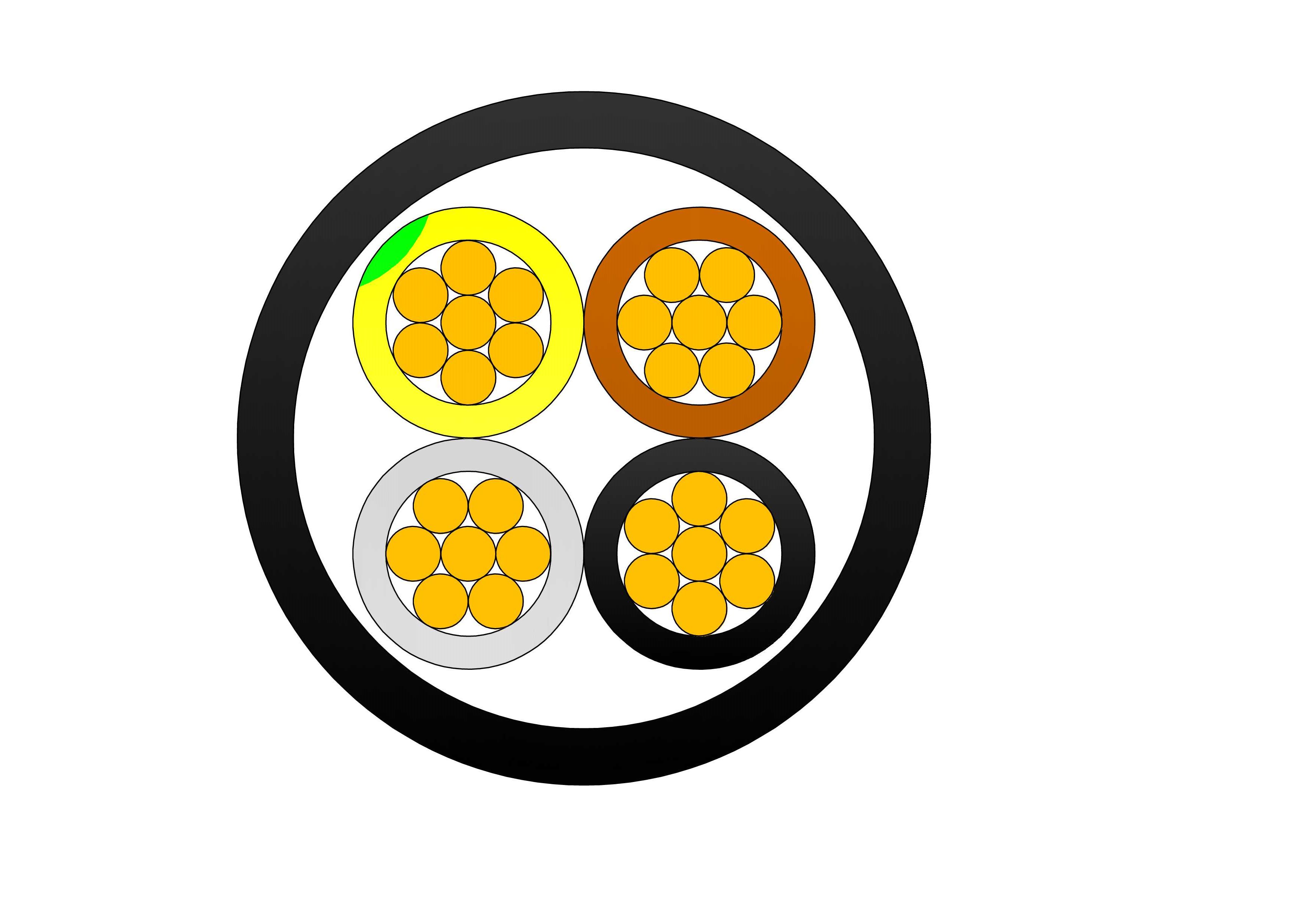
Steel Tape Armoured Cable Type
The Steel Tape Armoured Cable (STA Cable) is designed for reliable power transmission in environments requiring enhanced mechanical protection. Manufactured with high-quality copper or aluminum conductors, XLPE insulation, galvanized steel tape armour, and a durable PVC outer sheath, the cable provides exceptional durability and long-term operational reliability. The galvanized steel tape armour offers superior resistance against mechanical impact, compression, and external damage, making the cable suitable for underground installations and harsh industrial environments. The XLPE insulation ensures excellent electrical performance, low dielectric losses, and continuous operating temperatures up to 90°C. The PVC sheath protects the cable against moisture, chemicals, abrasion, and environmental exposure, extending service life and reducing maintenance requirements. Manufactured according to IEC 60502-1 and other international standards, the cable is widely used in power distribution networks, industrial facilities, infrastructure projects, renewable energy installations, and utility systems. The Steel Tape Armoured Cable combines electrical efficiency, mechanical strength, and installation flexibility, making it a dependable solution for demanding power distribution applications.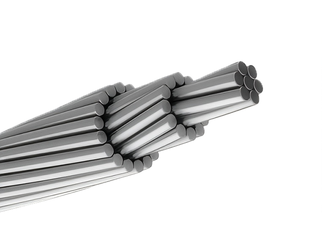
Quail ACSR Conductor Cable
Introducing the Quail ACSR Conductor Cable, a versatile 2/0 AWG overhead conductor with 6/1 stranding configuration. Composed of EC grade aluminum wires surrounding a galvanized steel core, it achieves a rated strength of 4,030 lbs and ampacity up to 250A at 75°C. Adhering to ASTM B230 for aluminum and B232 for assembly, this cable excels in corrosion resistance and mechanical endurance for spans up to 250m. The steel core enhances tensile strength to control sag under loads, while aluminum provides high conductivity (61.5% IACS) and a lightweight design for easier installation. Suitable for distribution voltages up to 138kV, the Quail ACSR Conductor Cable reduces line losses and withstands extreme weather, including ice loads up to 1/2 inch. Its economic profile makes it a staple for utility expansions, renewable integrations, and grid modernization, delivering consistent power with high weather tolerance and minimal maintenance in global overhead networks.
336.4 MCM MERLIN ACSR Conductor Cable
The ACSR CAA 336.4 KCM 18/1F MERLIN is a robust and efficient aluminium conductor steel reinforced cable, designed for high-performance in overhead power transmission and distribution lines. This conductor consists of 18 strands of hard-drawn 1350-H19 aluminium helically stranded around a single galvanized steel core wire, delivering an ideal combination of electrical conductivity and mechanical strength. Compliant with ASTM B232, this ACSR configuration is widely adopted in South American and international power systems. The steel core, galvanized to Class A or B, offers protection against corrosion, ensuring long service life in harsh environmental conditions. Meanwhile, the aluminium strands provide excellent current-carrying capacity and conductivity. The MERLIN design is particularly suitable for medium-voltage transmission lines and long-span installations where mechanical tension and conductor sag need to be controlled without compromising electrical performance.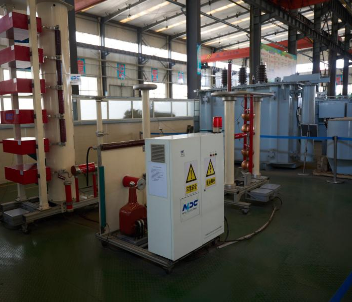
11/0.4kV Dry Type Transformer | Indoor Power Transformer
Discover the reliable 11/0.4kV Dry Type Transformer | Indoor Power Transformer, a safe, oil-free solution designed for efficient medium-to-low voltage conversion in indoor electrical installations. This three-phase dry-type transformer (typically cast resin or vacuum pressure impregnated) features premium low-loss silicon steel cores and high-conductivity copper windings, achieving superior energy efficiency often exceeding 98% and complying with IEC 60076-11 standards. The epoxy resin encapsulation provides excellent moisture resistance, fire self-extinguishing properties (F1 class), minimal partial discharge (<10pC), and robust short-circuit withstand capability. With natural air (AN) cooling and optional forced air (AF) upgrades, it offers low noise operation, Class F/H insulation, and maintenance-free performance in demanding environments. Ideal for step-down from 11kV primary (with ±2×2.5% or wider off-circuit taps) to 0.4kV secondary (Dyn11 vector group standard), this indoor power transformer supports capacities from 100kVA to several MVA, delivering stable, eco-friendly power distribution without oil-related risks.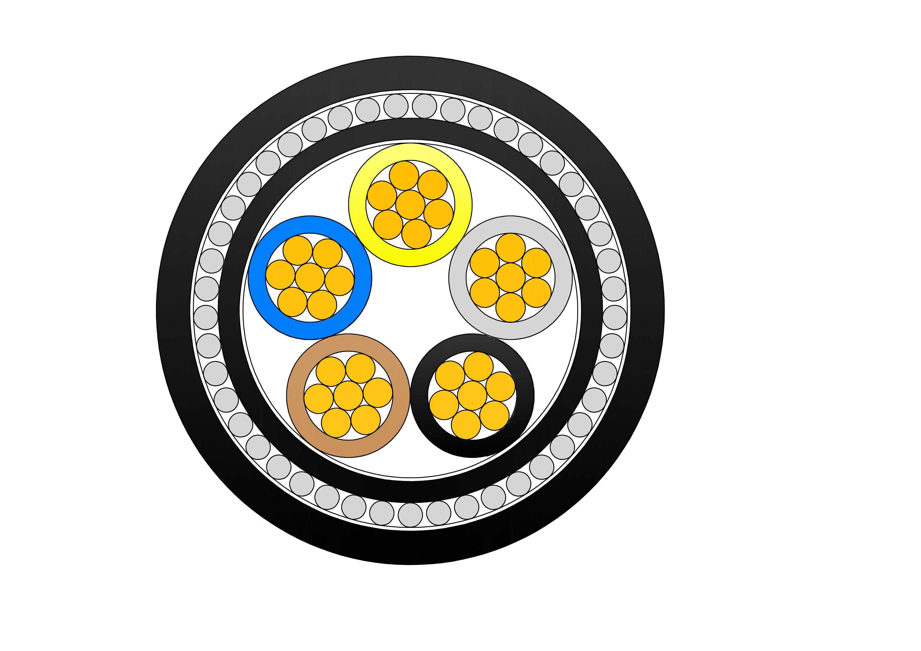
NYRY 0.6/1kV Low Voltage Power Cable
NYRY 0.6/1kV are low voltage power cables designed according to BS 5467 standard, suitable for fixed installation in indoor, outdoor, underground, cable ducts or concrete (not subject to vibration) environments, with steel wire armouring for mechanical protection. The cable features stranded copper conductors insulated with high-quality PVC, ensuring dependable electrical performance and thermal resistance under normal operating conditions. The metallic concentric conductor layer provides effective grounding and enhanced fault current capability, while the robust PVC outer sheath offers protection against moisture, abrasion, and external mechanical stress. Rated at 0.6/1kV and manufactured in accordance with relevant IEC standards, the NYRY cable is suitable for fixed installation both indoors and outdoors. Its construction supports long service life, consistent power delivery, and safe operation in demanding environments.
800kVA Oil Immersed Transformer
The NPC ELECTRIC 800kVA Oil-Immersed Transformer is designed for high efficiency, durability, and reliable power distribution. Built to meet IEC 60076 and ANSI/IEEE standards, it ensures superior performance and safety. Certified for international quality compliance, it is ideal for industrial, commercial, and utility applications. This 800 kVA unit delivers outstanding energy efficiency (>99.55% typical), low no-load and load losses, excellent thermal performance, and proven durability in demanding outdoor environments.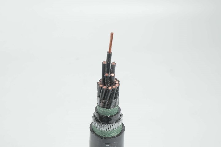
LiHH LSZH Control Cable - Halogen-Free Flexible Control Cable
The LiHH LSZH Control Cable is a high-performance halogen-free flexible control cable designed for applications requiring enhanced fire safety and low smoke emission. It features finely stranded copper conductors with low-smoke zero-halogen (LSZH) insulation, twisted cores, and a robust LSZH outer sheath. This construction provides excellent flexibility, reliable signal transmission, and superior fire performance with minimal toxic gas and smoke generation during combustion. Rated 300/500V, the LiHH LSZH Control Cable is ideal for public buildings, transportation systems, data centers, and industrial environments where safety and environmental protection are critical. Manufactured to international standards such as IEC 60227 and VDE 0812, it undergoes rigorous quality testing from raw materials to finished product, ensuring consistent electrical performance, mechanical strength, and compliance with strict fire safety regulations.
1/0 Janthina Aluminum Conductor Triplex Overhead Service Drop Cable
The 1/0 Janthina Triplex Service Drop Cable is a reliable overhead cable for secondary power distribution to residential service entrances. Featuring two 1/0 AWG aluminum phase conductors and one neutral messenger (7-strand) insulated with XLPE or PE and assembled in triplex configuration, it provides excellent mechanical strength and weather resistance. Compliant with ASTM B-230, B-231, ICEA S-76-474, and ANSI/ICEA standards, this cable supports 600V applications with high UV, moisture, and abrasion protection. The self-supporting messenger reduces sag and simplifies installation over medium spans. The 1/0 Janthina Triplex Service Drop Cable ensures low power losses, high current capacity, and long service life in harsh outdoor conditions. Lightweight and flexible, it is widely used for two-phase service drops with neutral in urban, suburban, and rural areas requiring safe, cost-effective aerial connections from utility poles to homes.
500kVA Three Phase Pad Mounted Transformer
The 500kVA three-phase pad transformer is an efficient and sturdy power equipment designed for commercial, industrial and distribution systems. It has a compact design and a protective casing that meets NEMA 3R or higher standards. It is suitable for various outdoor environments and can effectively resist external factors such as weather, dust and moisture. It can meet the power needs of different regions and has a variety of optional functions, such as load regulation and temperature control systems, to further improve its operating efficiency and safety. The built-in protection device can effectively prevent overload, short circuit and other faults to ensure the safe and reliable operation of the power system.
NTSCGECECWOU 3.6/6kV and 6/10kV Cable
The NTSCGECECWOU 3.6/6kV and 6/10kV cable is a flexible medium voltage power cable manufactured to VDE 0250 Part 813 standards, designed for reeling and trailing applications in mining, tunneling, and other demanding industrial environments. Constructed with Class 5 tinned copper conductors, EPR insulation, and a robust halogen-free sheath, it delivers exceptional mechanical strength, flame retardancy, oil resistance, and flexibility. Its copper wire screen ensures EMC protection, while the rugged sheath withstands extreme temperatures, making it suitable for both indoor and outdoor installations in harsh conditions.
2/0 Dungeness Aluminum Conductor Triplex Overhead Service Drop Cable
The 2/0 Dungeness Aluminum Conductor Triplex Overhead Service Drop Cable is engineered to provide safe and efficient overhead power distribution. Featuring two insulated aluminum conductors and a bare aluminum neutral messenger, this cable delivers strong mechanical support and stable electrical transmission. The 2/0 Dungeness Aluminum Conductor Triplex Overhead Service Drop Cable is manufactured using premium aluminum materials and weather-resistant insulation to ensure long service life in outdoor environments. Its optimized design allows for easy installation while maintaining compliance with utility and industry standards. The cable performs reliably under mechanical stress, temperature changes, and prolonged UV exposure. Strict quality control and systematic testing procedures are applied throughout production to ensure consistent performance and dependable field operation.Welcome your inquiry
Honesty, Integrity, Frugality, Activeness and Passion