Evaluation of Iron and Copper Losses in Transformers
2025-07-16
Any electrical equipment will experience losses during prolonged operation, and power transformers are no exception. The losses in power transformers are mainly divided into two parts: copper loss and iron loss.
Copper Loss
What is the Copper Loss
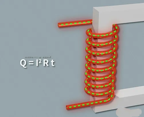
Copper plays an important role in transformers, as the windings typically use copper conductors. The "copper loss" in transformers refers to the losses generated by these copper conductors. Copper loss is also known as load loss, which is a variable loss that changes with operating conditions.
When a transformer operates under load, the current passing through the conductors encounters resistance, generating resistive losses. According to Joule's Law, this resistance generates Joule heat when current flows through it, and the higher the current, the greater the power loss. Thus, resistive losses are proportional to the square of the current and independent of voltage. Since copper loss varies with current magnitude, it is a variable loss and constitutes the primary loss during transformer operation.
Copper Loss Influencing Factors
- Current Magnitude: As mentioned, copper loss is proportional to the square of the current, making current magnitude a key factor.
- Winding Resistance: The resistance of the windings directly affects copper loss. Higher resistance leads to higher copper loss.
- Number of Coil Layers: More layers increase the path length for current flow in the windings, raising resistance and thus copper loss.
- Switching Frequency: The impact of switching frequency on copper loss is related to the transformer's distributed parameters and load characteristics. When the load characteristics and distributed parameters exhibit inductive behavior, copper loss decreases with increasing switching frequency; when they exhibit capacitive behavior, copper loss increases with frequency.
- Temperature Effects: Load losses are also influenced by transformer temperature. Additionally, leakage flux caused by load current generates eddy current losses within the windings and stray losses in the external metal parts.
Calculation Methods
There are two calculation formulas:
- Based on Rated Current and Resistance: Copper Loss (kW) = I² × Rc × Δt
Where:
- I: Rated current of the transformer.
- Rc: Resistance of the copper conductors.
- Δt: Operating time of the transformer.
- Based on Rated Current and Total Copper Resistance: Copper Loss = I² × R
Where:
- I: Rated current of the transformer.
- R: Total copper resistance of the transformer.
The total copper resistance R can be calculated as: R = (R1 + R2) / 2
Where:
- R1: Copper resistance of the primary side.
- R2: Copper resistance of the secondary side.
Methods to Reduce Copper Loss
- Increase Winding Cross-Sectional Area: Reduces conductor resistance, thereby lowering copper losses.
- Use High-Quality Conductor Materials: Such as copper foil or aluminum foil, to reduce winding resistance.
- Limit Light Load Operation Time: Reducing the proportion of light load operation helps lower copper losses.
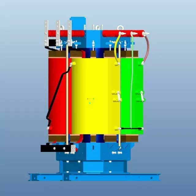
Iron Loss
What is the Iron Loss
Unlike copper loss, iron loss is unrelated to windings or current magnitude. As the name suggests, iron loss is associated with the iron core. It is also called "no-load loss" because it exists regardless of whether the transformer is fully loaded or unloaded, making it a fixed loss. However, under load conditions, power loss decreases as electric field strength diminishes.
types of Iron Loss
Iron loss is divided into hysteresis loss and eddy current loss.
1. Hysteresis Loss
The working principle of transformers relies on electromagnetic induction to achieve voltage transformation and current changes. The magnetic flux in the transformer flows through the iron core, which has magnetic resistance (similar to how conductors resist current flow), generating heat. This loss is called "hysteresis loss."
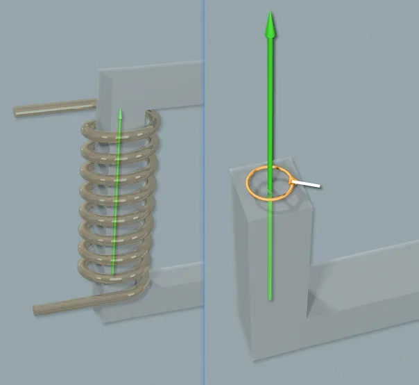
2. Eddy Current Loss
When the primary winding is energized, the magnetic flux generated by the coil flows through the iron core. Since the iron core itself is conductive, an electromotive force is induced perpendicular to the magnetic flux lines, forming a closed loop on the cross-section of the core and generating current—resembling a vortex. This current-induced loss is called "eddy current loss." To minimize eddy currents, the iron core is made into thin laminations because thinner cores have higher resistance and lower current.
Influencing Factors
- Operating Voltage and Frequency: Iron loss is related to the transformer's operating voltage and frequency, as these factors affect the magnetic field strength and hysteresis phenomena in the core.
- Core Material: The magnetic properties of the core material influence iron loss. Poor material selection increases hysteresis loss.
- Manufacturing Process: The transformer's manufacturing process also affects iron loss. For example, lamination methods and insulation treatment impact losses.
Calculation Methods
- Based on Rated Current and Hysteresis/Resistance Losses: Iron Loss (kVA) = I² × (Rm + Ra) Where:
- I: Rated current of the transformer.
- Rm: Hysteresis loss of the core.
- Ra: Resistance loss of the core.
- Based on Constants, Flux Density, and Frequency: P_iron = Kf × (Bm)^2 × f
Where:
- P_iron: Iron loss.
- Kf: Constant.
- Bm: Magnetic flux density.
- f: Transformer operating frequency.
Reduction Methods
- Select High-Quality Core Materials: Use materials with low hysteresis loss to reduce iron losses.
- Optimize Manufacturing Processes: Improve lamination methods and insulation treatment to lower losses.
- Rational Design: Optimize structural design and parameter selection during the design phase to minimize iron loss.
Impact of Transformer Iron Loss and Copper Loss on Maintenance and Servicing
Transformer iron loss and copper loss are critical factors affecting operational efficiency and thermal performance. Iron loss, caused by hysteresis and eddy currents in the core, occurs continuously—even under no-load conditions. Copper loss, on the other hand, results from the resistance of the windings when current flows through them and increases with load.
During Transformer maintenance and servicing, abnormal iron losses may indicate issues such as core overheating, insulation degradation, or mechanical loosening of the core assembly. Excessive copper losses often suggest problems like overloading, poor electrical connections, or winding faults such as short circuits. Regular monitoring of these losses enables maintenance personnel to identify early warning signs of failure, improve load management, and extend the transformer's operational lifespan.
Targeted maintenance actions—such as tightening core clamps, cleaning corrosion, replacing aged windings, or enhancing cooling systems—based on iron and copper loss analysis can significantly improve transformer reliability and efficiency.
Related Articles
Related Products
75kV 1250kVA Three Phase Oil Immersed Power Transformer Copper
The 75kV 1250kVA Three Phase Oil Immersed Power Transformer Copper is engineered for regional 66–75 kV transmission and industrial step-down applications. It adopts 99.99 % electrolytic copper windings, high-grade grain-oriented silicon steel S13 core, corrugated tank + ONAN cooling, and ±5 % off-circuit tap changer (on-load optional). Fully compliant with IEC 60076, lightning impulse withstand 350 kV peak, PD <10 pC, noise ≤58 dB. Fully sealed or conservator design with vacuum oil filling and nitrogen sealing ensures >30-year maintenance-free operation even in high-altitude or polluted areas. Ideal for mining, metallurgy, wind farms, and urban 75 kV substations requiring high reliability and low loss.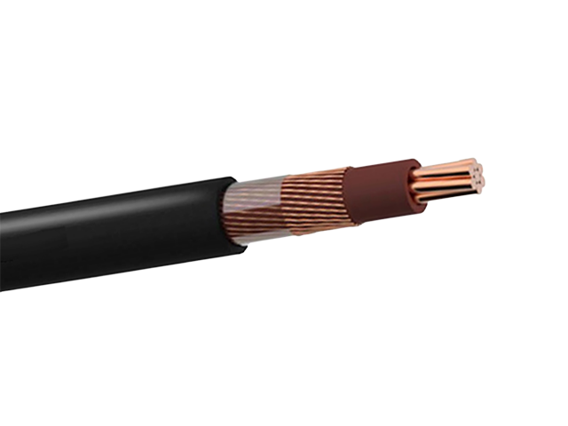
Copper Concentric Flat LV Cable 600/1000V
The Copper Concentric Flat LV Cable is engineered for safe and efficient low-voltage power delivery in residential and commercial applications. It consists of a stranded hard-drawn copper phase conductor with XLPE insulation, concentrically arranged copper neutral conductors, and a durable black polyethylene outer sheath. The flat design offers superior flexibility for easy installation in limited spaces while maintaining excellent electrical balance and mechanical protection. With high conductivity and UV-stabilized materials, this cable performs reliably in both overhead aerial and underground environments. The Copper Concentric Flat LV Cable meets international performance standards and undergoes extensive quality testing to ensure consistent performance, safety, and long service life for modern LV networks.
230kV 3-Phase Step-Down Power Transformer
The 230kV 3-Phase Step-Down Power Transformer is designed to reduce high transmission voltages to suitable distribution levels while maintaining excellent efficiency and operational stability. Engineered for utility substations and large-scale grid interfaces, this transformer ensures safe and controlled power delivery from high-voltage networks to regional or industrial distribution systems. Its oil-immersed insulation system provides strong dielectric protection and efficient thermal dissipation, enabling reliable continuous operation under varying load conditions. Precision core construction and optimized winding layout help minimize energy losses and voltage fluctuation. The transformer’s robust mechanical design enhances resistance to short-circuit forces and thermal stress, supporting long service life and low maintenance. This solution is ideal for modern power grids requiring dependable voltage transformation and efficient energy management.
220kV 230kV Power Transformer
The 220kV / 230kV Power Transformer is an extra-high-voltage, oil-immersed, three-phase power transformer engineered for backbone transmission networks, major utility substations, large-scale renewable energy integration, heavy industrial corridors, and cross-border grid interconnections. Typical specifications include mineral oil or FR3 natural ester insulation (ONAN/ONAF/ODAF/OFWF cooling configurations), high-conductivity copper windings (aluminum optional), primary voltages 220kV or 230kV (grounded wye/delta, dual-voltage or multi-tap options), secondary voltages 35kV, 66kV, 110kV, 132kV, 138kV or custom (e.g., 230kV/115kV, 220kV/35kV, 230kV/13.8kV step-down), BIL ratings 950–1050kV (up to 1175kV for ultra-high lightning areas), impedance 10–18% (tolerances ±7.5%), ±8×1.25% or ±10×1.25% off-load tap changer (OLTC ±16–25% range common), conservator with bladder or sealed tank, Buchholz relay, sudden pressure relay, oil/winding temperature indicators (OTI/WTI), fiber-optic hot-spot sensors, partial discharge monitoring, pressure relief device, and ANSI 61 gray or custom tank finish.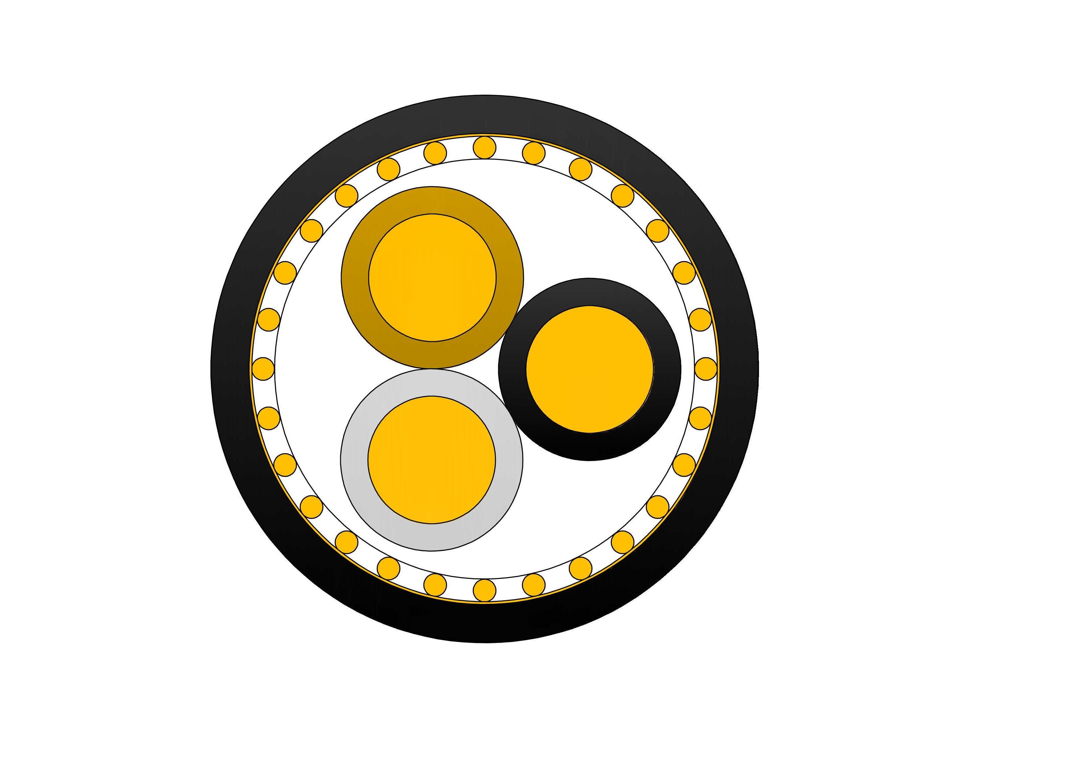
NYCY 0.6/1kV Low Voltage Power Cable
NYCY 0.6/1kV are low-voltage power cables designed according to VDE 0276 standard, suitable for fixed installation in indoor, outdoor, underground, cable ducts, or concrete (not exposed to mechanical vibration). Featuring stranded copper conductors, PVC insulation, filler, concentric copper wire screen with counter-helix tape, and robust PVC outer sheath, it complies with VDE 0276-603 and IEC standards. The concentric screen serves as neutral/earth conductor and provides excellent EMI shielding, reducing interference in sensitive areas. Suitable for direct burial, ducts, or indoor fixed installations, it offers good mechanical strength, moisture resistance, and flame-retardant properties. Copper conductors ensure low losses and high current capacity. The NYCY 0.6/1kV Low Voltage Power Cable delivers long service life with minimal maintenance, making it ideal for industrial plants, commercial buildings, residential networks, and infrastructure projects requiring screened, efficient low-voltage copper cabling for safe and interference-free energy transmission worldwide.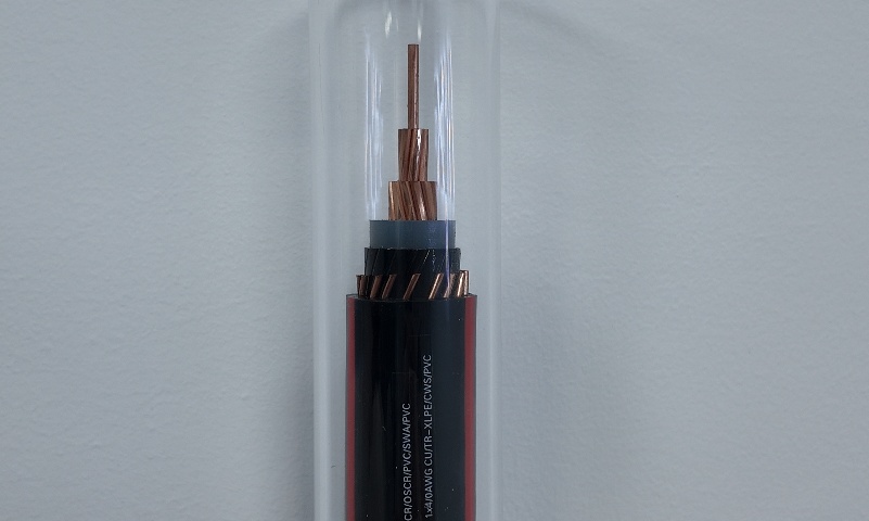
4/0 AWG Aluminum URD Cable 1/3 Neutral
The 4/0 AWG Aluminum URD Cable 1/3 Neutral is a durable and economical 600V underground residential distribution cable engineered for service entrance and secondary power delivery. It utilizes a 4/0 AWG stranded AA8000 aluminum alloy phase conductor with XLPE insulation and a 1/3 concentric aluminum alloy neutral, all protected by a rugged black polyethylene sheath. This design offers excellent flexibility, high conductivity, and superior moisture resistance, making it suitable for direct burial or conduit installations. The 1/3 neutral configuration provides a balanced and cost-effective solution for most residential applications. Manufactured to UL 854 and ICEA standards, the 4/0 AWG Aluminum URD Cable 1/3 Neutral undergoes extensive quality testing to ensure consistent performance and long service life in underground environments.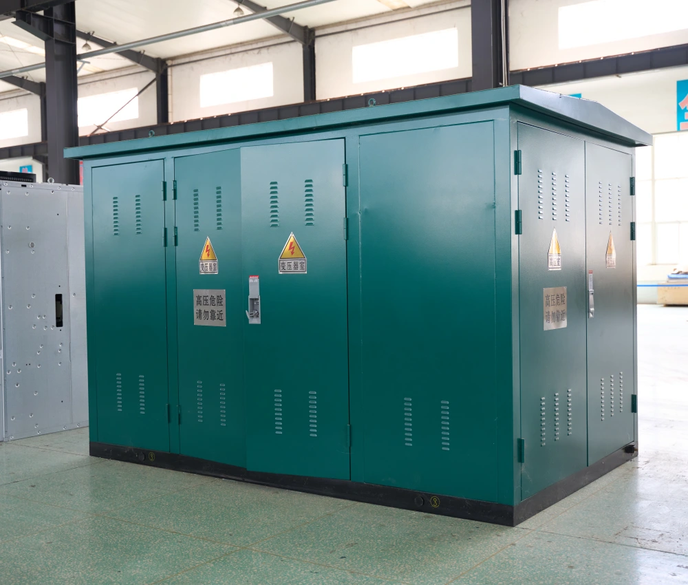
High Voltage Prefabricated Transformer Substation
The High Voltage Prefabricated Transformer Substation is a fully integrated power distribution system designed for high-voltage transmission and medium-voltage distribution applications in utility networks, renewable energy facilities, industrial plants, and infrastructure projects. The system integrates high-voltage switchgear, power transformers, low-voltage distribution equipment, intelligent protection devices, and automation systems within a compact modular enclosure to provide reliable and efficient electrical power transformation. Engineered for demanding outdoor operating conditions, the substation features a reinforced corrosion-resistant enclosure, advanced insulation technology, optimized thermal management systems, and intelligent safety protection structures. The prefabricated modular design significantly reduces civil construction requirements, shortens installation time, and improves transportation efficiency while maintaining high operational reliability and electrical safety performance. The High Voltage Prefabricated Transformer Substation supports flexible voltage classes, transformer capacities, and smart-grid communication interfaces, making it suitable for modern utility distribution systems, renewable energy integration projects, mining operations, oil and gas facilities, and industrial manufacturing plants. With customizable electrical configurations and intelligent monitoring functions, the substation delivers scalable and energy-efficient power distribution performance for complex electrical infrastructure applications.
266.8 MCM Waxwing ACSR Conductor Cable
The Waxwing ACSR Conductor Cable is engineered for demanding overhead transmission, with 266.8 MCM size and 18/1 stranding configuration. High-purity aluminum (1350-H19) surrounds a galvanized steel core, offering a DC resistance of 0.0643 Ω/MFT and ampacity up to 340A. Adhering to ASTM B230 for aluminum and B232 for assembly, it provides excellent corrosion resistance and mechanical integrity for spans up to 300m. The steel core minimizes sag under heavy loads, while aluminum ensures high conductivity (61.5% IACS) and lightweight design for easier installation. Suitable for distribution voltages up to 138kV, the Waxwing ACSR Conductor Cable reduces line losses and withstands extreme weather, including ice loads up to 1/2 inch. Its economical profile makes it a staple for utility expansions, renewable connections, and grid modernization, delivering consistent power with high weather tolerance and minimal maintenance in global overhead networks.
4 Strombus Aluminum Conductor Triplex Overhead Service Drop Cable
4 Strombus Aluminum Conductor Triplex Overhead Service Drop Cable is designed for reliable overhead power distribution from utility lines to service entrances of residential, commercial, and light industrial buildings. This cable consists of two insulated phase conductors and one bare or insulated neutral messenger made from high-purity aluminum, ensuring excellent conductivity, reduced weight, and long service life. The 4 Strombus Aluminum Conductor Triplex Overhead Service Drop Cable is manufactured using precision stranding and advanced insulation extrusion technology, providing stable electrical performance and strong mechanical strength. The insulation material offers excellent resistance to weathering, UV radiation, moisture, and temperature fluctuations, making the cable suitable for long-term outdoor installation. To guarantee consistent quality, the 4 Strombus Aluminum Conductor Triplex Overhead Service Drop Cable undergoes a comprehensive testing system covering raw materials, production processes, and finished products. Each stage follows standardized testing procedures to ensure compliance with international standards and utility requirements. This cable is an ideal solution for cost-effective, safe, and efficient overhead service drop applications.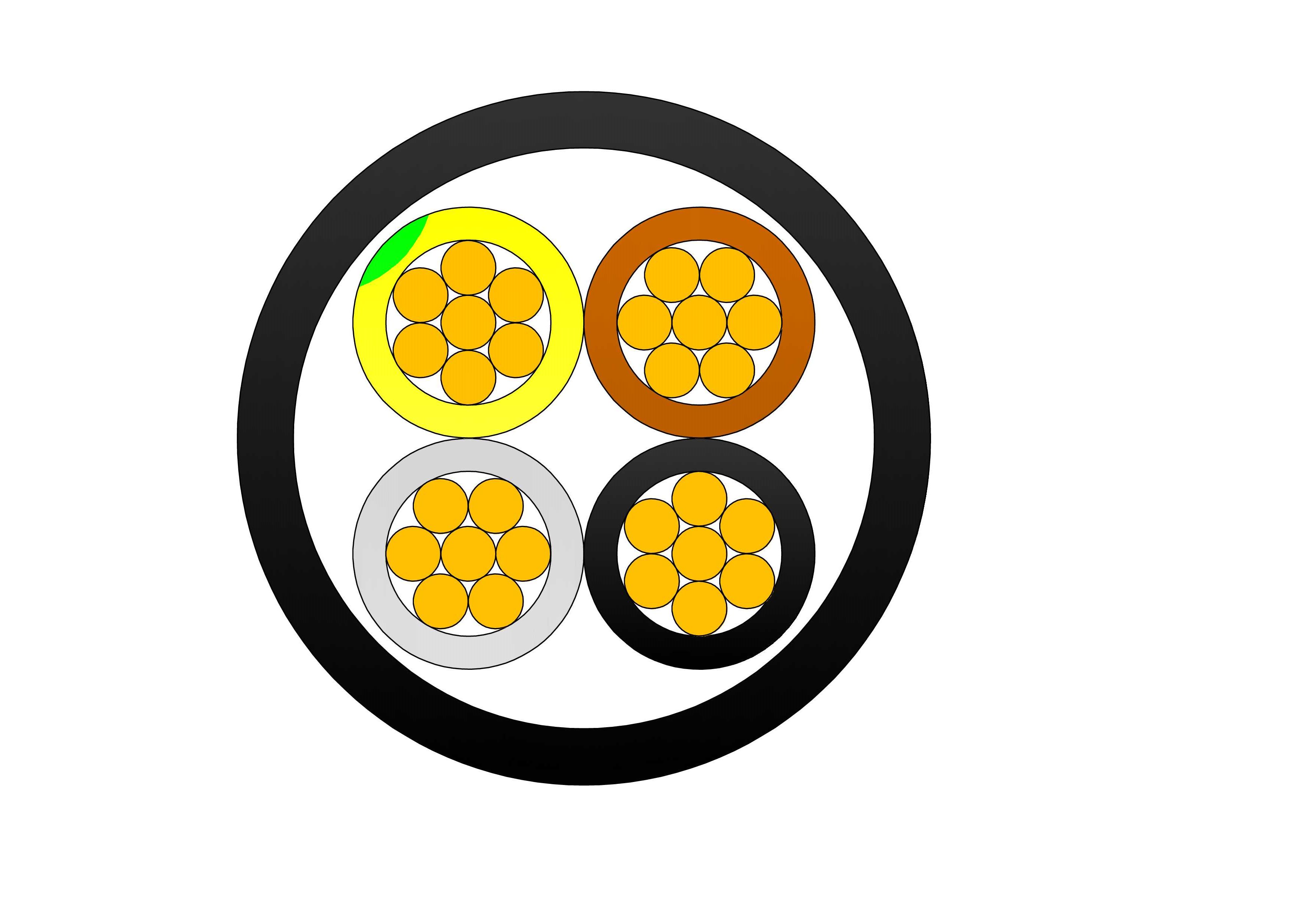
Solar Cable Aluminum Single/Twin Core
Solar Cable Aluminum Single/Twin Core is designed for modern photovoltaic power generation systems, providing a reliable and cost-effective solution for solar energy transmission. Manufactured with high-performance AA-8000 series aluminum alloy conductors and premium XLPE insulation, the cable delivers excellent electrical performance, lightweight installation advantages, and long-term operational reliability. The aluminum alloy conductor offers high conductivity, superior flexibility, and enhanced corrosion resistance compared to conventional aluminum conductors. The XLPE insulation provides excellent thermal stability, UV resistance, ozone resistance, moisture protection, and weather durability, ensuring dependable operation in demanding outdoor environments. Available in both single-core and twin-core configurations, the cable is suitable for interconnecting solar panels, combiner boxes, inverters, battery storage systems, and DC distribution equipment. Its lightweight construction reduces transportation and installation costs while maintaining efficient power transmission.
954 MCM RAIL ACSR Conductor Cable
The ACSR CAA 954 MCM 45/7F RAIL is a robust Aluminium Conductor Steel Reinforced (ACSR) cable designed to meet the demanding requirements of modern overhead transmission and distribution systems. It consists of 45 hard-drawn 1350-H19 aluminium strands concentrically wound around 7 galvanized steel strands, forming a high-capacity conductor with a reliable strength-to-conductivity ratio. Manufactured in accordance with ASTM B232, the RAIL configuration is ideal for long-span installations where increased tensile strength and environmental durability are essential. The galvanized steel core, coated to Class A or B standards, provides corrosion resistance and mechanical reinforcement against environmental stressors like wind, ice loading, and mechanical tension. This ACSR design supports efficient power delivery across overhead transmission networks, while also serving as a dependable solution for primary and secondary distribution lines. Suitable for voltages up to 230kV in distribution lines, the Rail ACSR Conductor Cable minimizes line losses and withstands harsh weather, including wind and ice loading.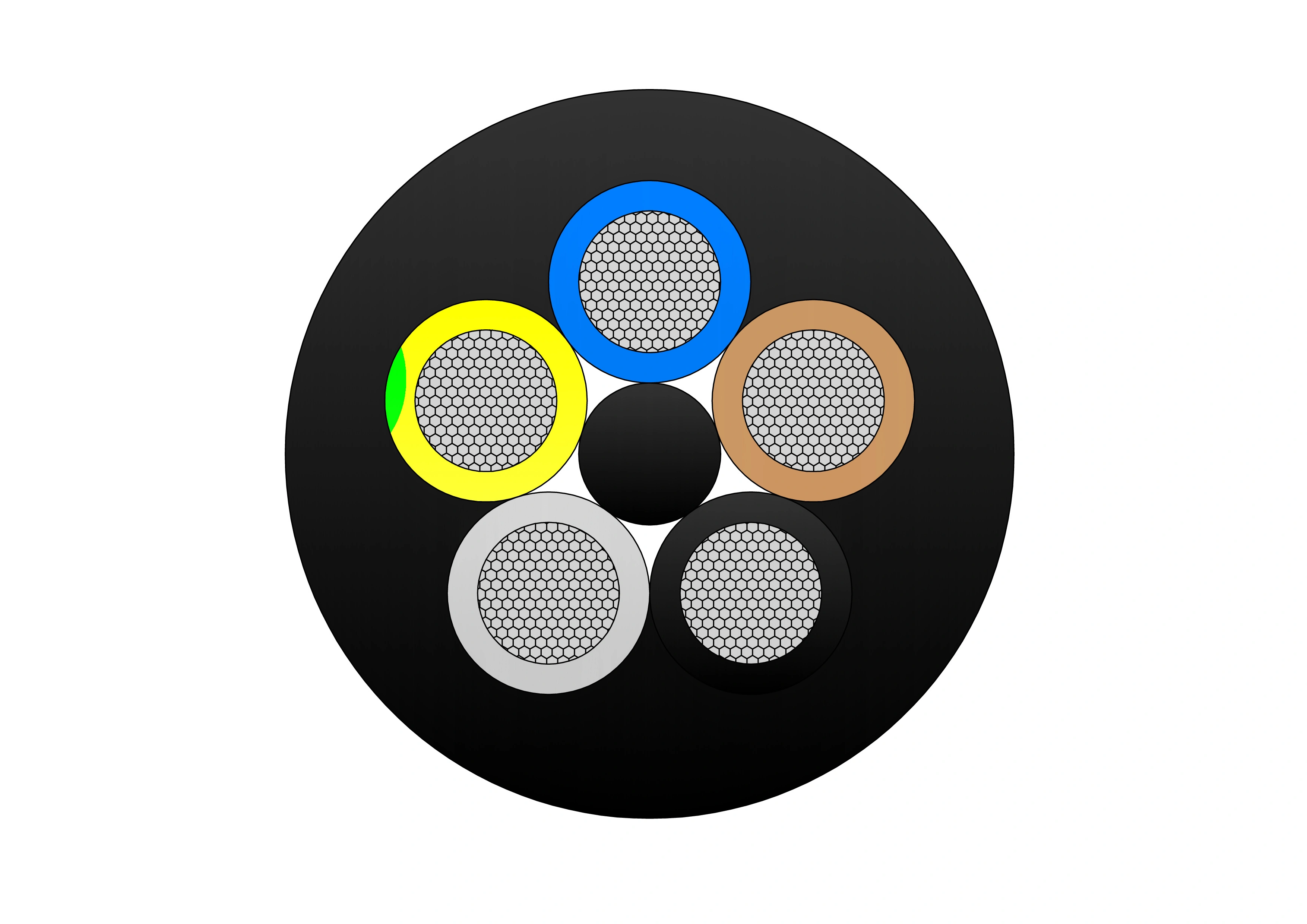
(N)TSCGEWOU 3.6/6kV, 6/10kV, 8.7/15kV and 12/20kV ATB Cable
The (N)TSCGEWOU 3.6/6kV, 6/10kV, 8.7/15kV, and 12/20kV ATB Cable is a medium voltage flexible power cable designed in compliance with VDE 0250 standards. It features Class 5 tinned copper conductors, EPR rubber insulation, semi-conductive layers, halogen-free flame-retardant rubber sheath, and an earth detection conductor. The ATB construction ensures superior mechanical strength, oil resistance, abrasion resistance, and flame retardancy, making it ideal for open-pit mining, tunneling, and other heavy-duty mobile equipment applications under extreme mechanical stress. It includes tinned class 5 copper phase conductors, semi-conductive screens, EPR insulation for reliable dielectric and thermal performance (90°C rating), copper braid screen, control conductors, monitoring conductor (ÜL), anti-torsion braid to reduce twisting under load, and a robust rubber sheath resistant to oils, flames, abrasion, and mechanical damage.
4/0 Cerapus Aluminum Conductor Triplex Overhead Service Drop Cable
4/0-4/0-2/0 Cerapus Aluminum Conductor Triplex Overhead Service Drop Cable provides premium overhead power transmission for utility-to-consumer connections with elevated capacity needs. Featuring concentric or compressed 1350-H19 aluminum phase conductors (#4/0 AWG), black XLPE insulation for enhanced thermal, abrasion, and environmental protection, plus a bare ACSR neutral messenger (#2/0 AWG), it ensures efficient conductivity, corrosion resistance, and structural integrity. Rated 600V phase-to-phase up to 90°C (XLPE), with ≈315A ampacity, it complies with ASTM B-230/B-231/B-232/B-399 and ICEA S-76-474. Its balanced, lightweight design facilitates easy installation while offering robust long-term performance against demanding outdoor factors like extreme temperatures, moisture, UV exposure, and mechanical loads in residential, commercial, and light industrial settings.
2 AWG IRIS AAC Cable
The 2 AWG IRIS AAC Cable is a premium All Aluminum Conductor designed for efficient overhead power transmission and distribution. Manufactured with high-purity 1350-H19 aluminum wires in a 7-strand concentric lay configuration, this bare conductor offers excellent electrical conductivity and lightweight performance. Ideal for urban and rural utility networks, the IRIS AAC delivers superior current-carrying capacity up to 185 amps while maintaining low sag and high reliability in various weather conditions. Its corrosion-resistant properties ensure long service life with minimal maintenance. Rigorously tested from raw materials to finished product, the 2 AWG IRIS AAC Cable meets or exceeds ASTM B-230 and B-231 standards, providing optimal strength-to-weight ratio and low DC resistance of 0.260 ohms per 1000ft. Choose this dependable solution for cost-effective power delivery in overhead lines on poles and towers.
125kVA Cast Resin Dry Type Transformer 3 Phase 10kV/0.4kV Copper Winding IEC Certified
The 125kVA Cast Resin Dry Type Transformer is a compact, three-phase, high-efficiency indoor power transformer engineered for safe and reliable voltage transformation in commercial, institutional, and light-to-medium industrial environments. Featuring advanced cast-resin encapsulation and full copper windings, it eliminates oil-related fire hazards, environmental risks, and routine maintenance while delivering superior performance in confined spaces, high-rise buildings, hospitals, schools, data centers, office complexes, and renewable energy tie-in applications. Fully compliant with IEC 60076-11, IEC 60076-1, IEC 60076-3, IEC 60076-5, IEC 60076-20, IEEE C57.12.01, IEEE C57.12.91, UL 1561 (optional), and DOE 2016 efficiency standards.Welcome your inquiry
Honesty, Integrity, Frugality, Activeness and Passion