What is a Rectifier Transformer? Differences from Power Transformer Explained
2026-05-13
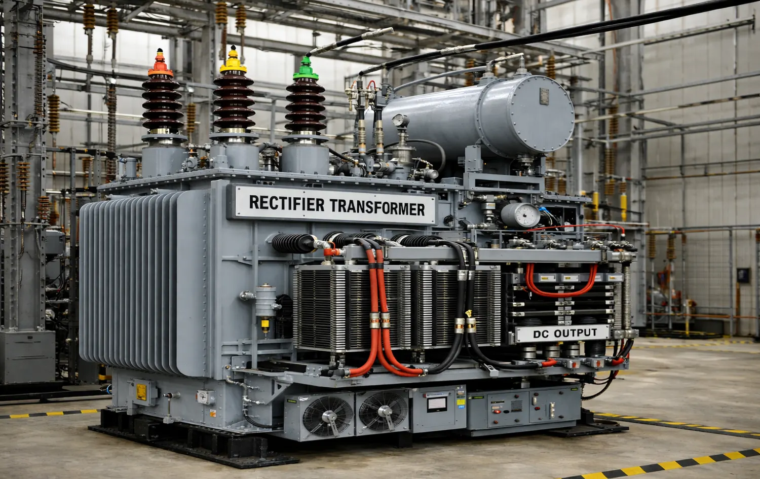
Modern industrial processes require reliable DC power systems. Since electrical grids generate AC power, specialized equipment must convert this energy into DC voltage and a DC supply for industrial applications. A Rectifier Transformer is a specially designed type of transformer used to supply AC power to rectifier circuits that convert AC into DC power. Unlike conventional power transformers, which only adjust voltage levels for transmission and distribution, rectifier transformers are optimized to handle nonlinear loads, harmonic currents, and high DC power demand.
These transformers are widely used in:
- Electrolysis plants
- Aluminum smelting
- Electroplating industries
- Railway traction power supply
- HVDC power transmission
- Industrial DC power systems
1. Transformer Rectifier Machine Definition
A Transformer Rectifier Machine (also known as a transformer rectifier unit, rectifier transformer system, or rectifier duty transformer set) is a specialized industrial power conversion device that combines a rectifier transformer with a rectifier bridge (typically using diodes or thyristors/SCRs). It steps down and isolates the incoming AC voltage from the grid, then converts it to direct current (DC) output through rectification.
Unlike standard power transformers, it is engineered to handle non-linear loads, high harmonic currents, commutation stresses, and extra heating. Multi-pulse configurations (e.g., 6-pulse, 12-pulse, 24-pulse) reduce harmonics. Widely used in electrolysis, aluminum smelting, electroplating, metal refining, traction, DC drives, and heavy industrial DC power supplies.
Rectifier Transformer Definition Table
|
Term |
Explanation |
|
Rectifier Transformer |
Transformer supplying AC power to rectifier circuits |
|
Transformer Rectifier Unit |
Combined transformer + rectifier system |
|
Rectifier Duty Transformer |
Transformer designed for harmonic loads |
|
Power Rectifier Transformer |
High-capacity rectifier transformer for industry |
The transformer ensures that the voltage level and phase configuration match the requirements of the rectifier system.
2. How a Rectifier Transformer Works
A rectifier transformer (also called a rectifier duty transformer) is a specialized power transformer designed to feed rectifier circuits that convert high-power AC (alternating current) from the grid into DC (direct current). It differs from standard transformers because it must handle non-linear loads, heavy harmonic currents, commutation notches, and extra heating caused by rectification.
Step-by-Step Working Principle
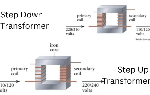
- Voltage Transformation (Electromagnetic Induction) The rectifier transformer operates on the same basic principle as any power transformer: Faraday's law of electromagnetic induction.
- AC voltage is applied to the primary winding (usually connected to the utility grid, e.g., 11 kV or 33 kV).
- Alternating current in the primary creates a changing magnetic flux in the iron core.
- This flux links to the secondary winding(s), inducing a lower (or sometimes higher) AC voltage at the desired level for the rectifier (typically hundreds to a few thousand volts).
- Multi-Secondary Windings & Phase Shifting. Unlike ordinary transformers, rectifier transformers almost always feature multiple secondary windings configured to produce phase-shifted outputs:
- Common setups: delta-star, extended delta, zigzag, or polygon connections.
- Typical phase shifts: 30° (for 12-pulse), 15° (for 24-pulse), etc.
- Purpose: Create multiple AC supplies offset in phase → when rectified, their DC ripples partially cancel each other → smoother DC output with fewer harmonics injected back into the grid.
- Rectification Stage (AC → DC Conversion) Each secondary winding feeds a rectifier bridge (usually 6 diodes or thyristors/SCRs per bridge):
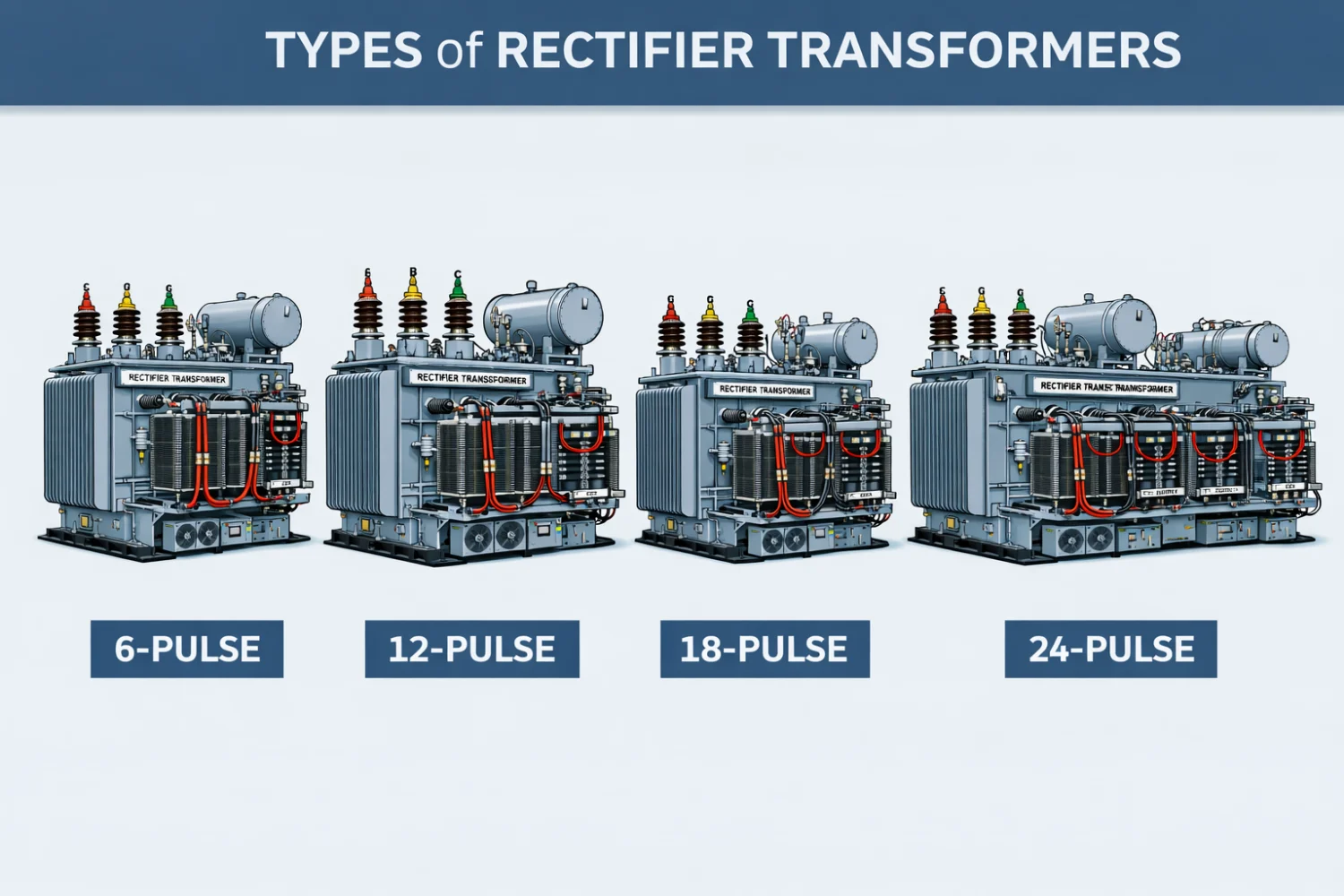
- 6-pulse rectifier (single bridge): Produces 6 pulses per cycle → significant ripple and harmonics (5th, 7th, 11th, 13th dominant).
- 12-pulse (two bridges + 30° shift): Cancels 5th & 7th harmonics → only 11th, 13th remain (much lower THD).
- 24-pulse (four bridges with 15° shifts): Further reduces harmonics to 23rd/25th → very clean DC, common in high-power electrolysis or HVDC. The rectifier "chops" the AC waveform, allowing current to flow only in one direction → pulsating DC output.
- Output Smoothing & Load: The pulsating DC is usually smoothed with:
- DC inductors (chokes) → reduce current ripple.
- Capacitors or LC filters → flatten voltage. Final stable DC feeds heavy industrial loads like aluminum smelters, copper electrolysis, chlor-alkali plants, traction substations, electroplating, or DC arc furnaces.
Key Visual Concept
Imagine a standard sine wave AC input → transformer steps it down and splits it into phase-shifted versions → each feeds its own diode bridge → overlapping DC pulses combine into nearly flat DC with minimal ripple and harmonics.
Advantages of Multi-Pulse Designs
- Dramatically lower input current harmonics (meets IEEE 519, IEC 61000 standards).
- Smoother DC output → less stress on load and better efficiency.
- Higher pulse number = cleaner system, but more complex & expensive transformer.
In summary: The rectifier transformer first transforms & isolates AC voltage (with clever phase-shifting windings), then supplies multiple offset AC feeds to rectifier bridges, which convert it to high-quality DC while minimizing grid pollution.
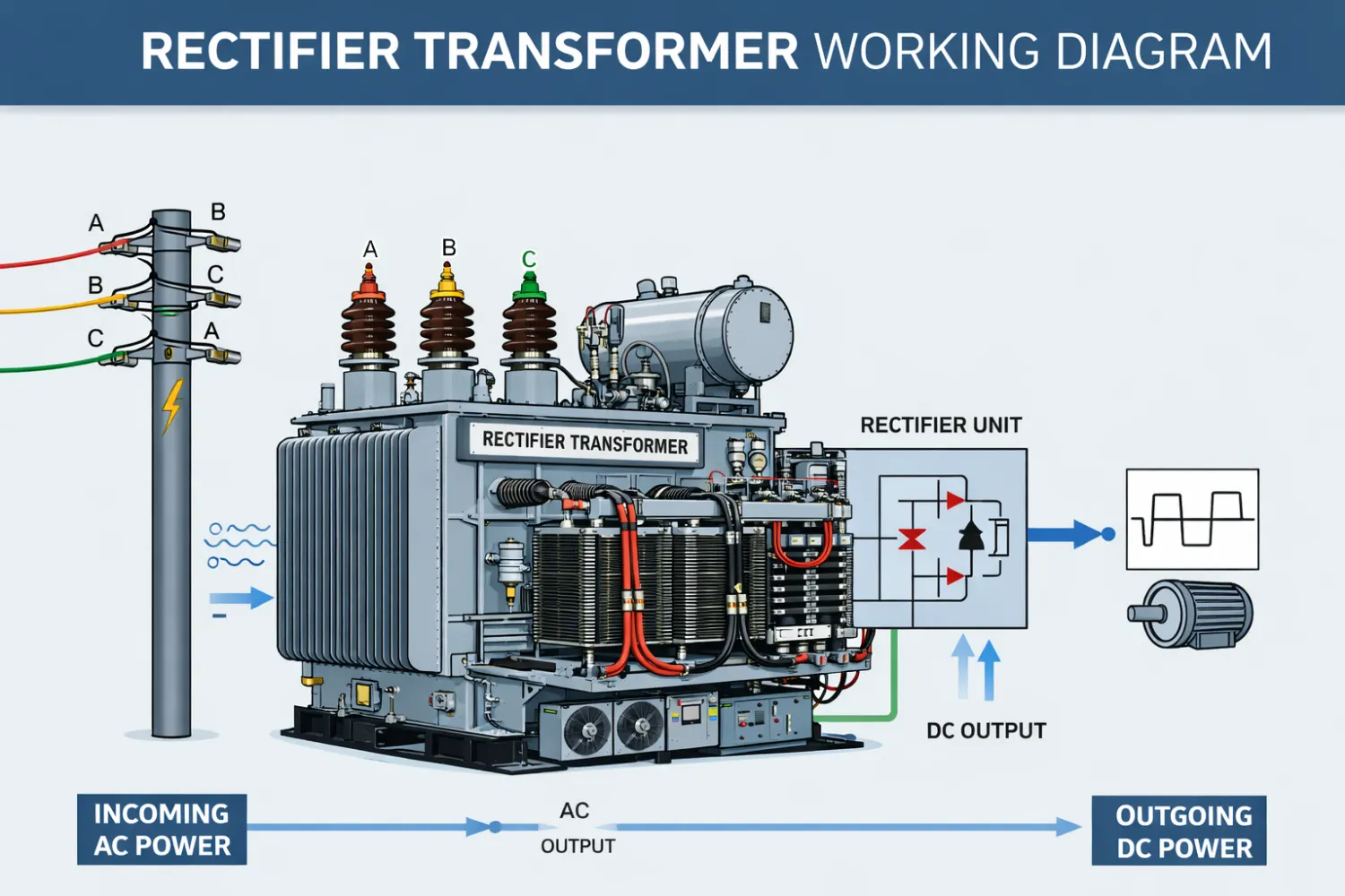
3. Rectifier Transformer Working Diagram
Understanding the electrical configuration is easier through a rectifier transformer diagram.
Basic Rectifier Transformer Structure
|
Component |
Function |
|
Primary Winding |
Receives AC power from the grid |
|
Secondary Winding |
Supplies voltage to the rectifier |
|
Rectifier Bridge |
Converts AC into DC |
|
Filter System |
Smooths DC voltage |
|
Load |
Industrial equipment requiring DC power |
Simplified Power Flow
AC Grid
   │
Primary Winding
   │
Rectifier Transformer
   │
Secondary Winding
   │
Rectifier Circuit
   │
DC Output
   │
Industrial Load
This configuration forms the foundation of transformer rectifier units used in industrial DC power systems.
4. Rectifier Transformer Design
The rectifier transformer design differs significantly from conventional transformers due to special operating conditions.
Key Design Features
|
Design Element |
Purpose |
|
Multiple secondary windings |
Feed rectifier bridges |
|
Phase shifting |
Reduce harmonics |
|
High current capability |
Support DC load |
|
Enhanced insulation |
Handle voltage stress |
|
Thermal management |
Prevent overheating |
These design features allow rectifier transformers to operate reliably under nonlinear electrical loads.
5. Rectifier Transformer Pulse System (6-Pulse vs 12-Pulse)
Rectifier transformers are often designed to support multi-pulse rectification systems.
Pulse System Comparison
|
Feature |
6-Pulse Rectifier |
12-Pulse Rectifier |
|
Harmonic distortion |
Higher |
Lower |
|
Power quality |
Moderate |
High |
|
Efficiency |
Good |
Very high |
|
System complexity |
Simple |
More complex |
|
Typical use |
Medium power systems |
High-power industrial systems |
Most power rectifier transformers used in heavy industry utilize 12-pulse systems to reduce harmonic distortion.
6. Types of Rectifier Transformers
Different industrial environments require different transformer configurations.
Common Rectifier Transformer Types
|
Transformer Type |
Description |
Application |
|
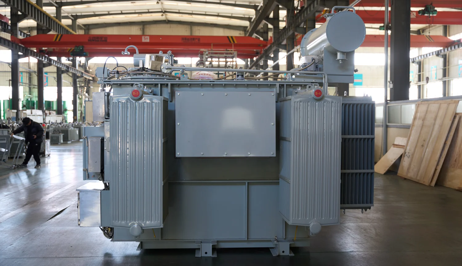
Oil Type Rectifier Transformer |
Oil cooled for heavy loads |
Smelting plants |
|
Dry Type Rectifier Transformer |
Air cooled indoor systems |
Industrial facilities |
|
HVDC Rectifier Transformer |
Ultra high voltage applications |
HVDC transmission |
|
Industrial Rectifier Transformer |
Designed for electrochemical processes |
Electrolysis plants |
Among these, Oil Type Rectifier Transformers are the most widely used due to their high thermal capacity and reliability.
7. Rectifier Transformer Harmonic Analysis
One of the most critical engineering challenges in rectifier transformer design is managing harmonic distortion. When AC power passes through rectifier circuits, nonlinear loads generate harmonic currents that can affect both the transformer and the power grid.
Harmonics can cause:
- Excessive transformer heating
- Increased core losses
- Reduced system efficiency
- Power quality issues in the grid
Therefore, rectifier transformers are designed with harmonic mitigation techniques.
Common Harmonic Orders in Rectifier Systems
|
Rectifier Type |
Dominant Harmonics |
|
6-Pulse Rectifier |
5th, 7th, 11th, 13th |
|
12-Pulse Rectifier |
11th, 13th |
|
24-Pulse Rectifier |
Very low harmonic distortion |
Using phase-shifting transformer windings, engineers can significantly reduce harmonic currents.
Harmonic Reduction Methods
|
Method |
Description |
|
Phase shifting |
Reduces harmonic overlap |
|
Multi-pulse rectifier systems |
Improves power quality |
|
Harmonic filters |
Removes distortion from grid |
|
Transformer impedance design |
Limits harmonic current |
Because of these design improvements, rectifier duty transformers maintain stable performance even under heavy industrial loads.
8. Rectifier Transformer Capacity Chart (500kVA–100MVA)
Rectifier transformers are manufactured in a wide range of power ratings.
Industrial Rectifier Transformer Capacity Table
|
Capacity |
Typical Application |
|
500 kVA |
Small electroplating systems |
|
1 MVA |
Chemical processing plants |
|
5 MVA |
Industrial DC power supply |
|
10 MVA |
Steel and metal processing |
|
20 MVA |
Aluminum smelting |
|
50 MVA |
Large electrolysis plants |
|
100 MVA |
HVDC converter stations |
Large systems may operate with multiple transformers in parallel to meet industrial power demand.
9. Rectifier Transformer vs Power Transformer
Although both are types of transformers, their design purposes are different.
Comparison Table
|
Feature |
Rectifier Transformer |
Power Transformer |
|
Main function |
AC to DC conversion support |
Voltage transformation |
|
Electrical load |
Nonlinear |
Linear AC load |
|
Harmonic tolerance |
High |
Low |
|
Secondary winding |
Multiple phase configurations |
Standard windings |
|
Typical industries |
Electrochemical industry |
Power grid |
Rectifier transformers must tolerate high harmonic distortion and fluctuating loads, which makes their design more complex.
10. Industrial Applications of Rectifier Transformers
Rectifier transformers are critical for industries requiring a large DC power supply.
Major Applications
|
Industry |
Application |
|
Aluminum smelting |
Electrolytic reduction |
|
Hydrogen production |
Water electrolysis |
|
Electroplating |
Surface metal treatment |
|
Railway electrification |
DC traction systems |
|
HVDC transmission |
Long distance power transmission |
These industries rely on stable DC power output for continuous production processes.
11. Rectifier Transformer vs Converter Transformer
Many engineers confuse rectifier transformers with converter transformers, especially in large power systems such as HVDC transmission.
Although both transformers are used in AC-DC power conversion, they serve slightly different purposes.
Comparison Table: Rectifier Transformer vs Converter Transformer
|
Feature |
Rectifier Transformer |
Converter Transformer |
|
Main purpose |
Supply rectifier circuits |
Used in HVDC converter stations |
|
Power level |
Medium to high industrial power |
Extremely high power |
|
Typical voltage |
Medium voltage |
Ultra high voltage |
|
Application |
Electrolysis, electroplating |
HVDC power transmission |
|
Harmonic design |
Multi-pulse winding |
Complex harmonic control |
|
Cooling system |
Oil or dry type |
Large oil-immersed systems |
Converter transformers are usually very large power transformers used in HVDC systems, while rectifier transformers are widely used in industrial DC power applications.
Rectifier Transformer Cooling Systems
Efficient cooling is essential for maintaining long-term transformer reliability, especially because rectifier transformers operate with high current loads.
Common Cooling Methods
|
Cooling Type |
Description |
Application |
|
ONAN |
Oil Natural Air Natural |
Small industrial systems |
|
ONAF |
Oil Natural Air Forced |
Medium capacity transformers |
|
OFAF |
Oil Forced Air Forced |
High-power rectifier transformers |
|
Dry Air Cooling |
Air-cooled transformer |
Indoor installations |
Oil-immersed designs provide excellent heat dissipation and electrical insulation, which is why Oil Type Rectifier Transformers are widely used in heavy industry.
12. Rectifier Transformer Efficiency Optimization
Improving efficiency is one of the key objectives in rectifier transformer engineering. Losses in transformers mainly come from two sources:
- Core losses
- Copper losses
Transformer Loss Components
|
Loss Type |
Cause |
|
Core loss |
Magnetic hysteresis and eddy currents |
|
Copper loss |
Current flowing through windings |
|
Stray loss |
Leakage magnetic fields |
|
Harmonic loss |
Nonlinear rectifier loads |
Efficiency Improvement Techniques
|
Technique |
Benefit |
|
High-grade silicon steel core |
Reduces core loss |
|
Optimized winding design |
Improves current distribution |
|
Advanced insulation materials |
Enhances reliability |
|
Harmonic optimized design |
Reduces additional heating |
These improvements allow modern power rectifier transformers to achieve efficiency levels above 98% in large industrial systems.
13. Future Trends in Rectifier Transformer Technology
With the growth of renewable energy and advanced industrial processes, rectifier transformer technology continues to evolve.
Key technological trends include:
- Smart monitoring systems
- Digital transformer diagnostics
- Advanced insulation materials
- Higher efficiency magnetic cores
- Integration with power electronics
Modern rectifier transformers are increasingly integrated into smart industrial power systems, enabling predictive maintenance and improved reliability.
14. Transformer Rectifier Unit (TRU)
A Transformer Rectifier Unit (TRU) integrates both the transformer and rectifier in a single system.
TRU Components
|
Component |
Function |
|
Rectifier Transformer |
Voltage conversion |
|
Rectifier Bridge |
AC-DC conversion |
|
Control System |
Regulates output voltage |
|
Cooling System |
Maintains temperature |
TRUs are widely used in aerospace, railway power supply, and industrial DC systems.
15. Advantages of Rectifier Transformers
Rectifier transformers offer several operational advantages.
Key Benefits
|
Advantage |
Description |
|
Stable DC power |
Reliable industrial operation |
|
Harmonic reduction |
Improved grid power quality |
|
High current capacity |
Supports heavy industrial loads |
|
Flexible voltage design |
Customizable output levels |
These features make rectifier transformers essential equipment in modern power electronics systems.
16. How to Select a Rectifier Transformer
Selecting the correct transformer requires careful engineering evaluation.
Selection Criteria
|
Parameter |
Importance |
|
DC output voltage |
Must match process requirements |
|
Transformer capacity |
Supports load current |
|
Pulse configuration |
Determines harmonic levels |
|
Cooling system |
Ensures long life |
|
Insulation system |
Protects against voltage stress |
Proper selection ensures long-term reliability and efficient industrial power conversion.
A Rectifier Transformer is a specialized electrical device designed to supply AC power to rectifier circuits that generate DC voltage and DC power for industrial applications.
Compared with conventional power transformers, rectifier transformers are engineered to handle harmonics, high current loads, and nonlinear power conditions.
From Oil Type Rectifier Transformers used in heavy industry to large HVDC rectifier transformers used in power transmission, these systems are essential components in modern industrial infrastructure.
As industries continue to expand electrochemical processing, renewable energy systems, and DC power technologies, advanced rectifier transformer design and manufacturing will remain critical for efficient power conversion.
Related Articles
Related Products
3+2 Cores Copper Cable CU/XLPE/PVC 0.6/1kV
The Single Core Copper Cable CU/XLPE/PVC 0.6/1kV is engineered for reliable power transmission and distribution in industrial, commercial, and utility applications. Featuring a high-purity copper conductor, XLPE insulation, and durable PVC outer sheath, the cable delivers outstanding electrical conductivity, thermal stability, and mechanical protection. The XLPE insulation offers superior dielectric properties, allowing the cable to operate continuously at conductor temperatures up to 90°C while maintaining excellent insulation performance. The PVC sheath provides resistance against moisture, abrasion, chemicals, and environmental exposure, ensuring a long service life even in demanding installations. Designed according to international standards including IEC 60502-1, this cable is suitable for fixed installations in power networks, industrial facilities, commercial buildings, renewable energy projects, and infrastructure developments. Various conductor sizes and sheath colors can be customized to meet specific project requirements. Its combination of safety, durability, and efficient power transmission makes the Single Core Copper Cable CU/XLPE/PVC 0.6/1kV a dependable solution for modern electrical systems.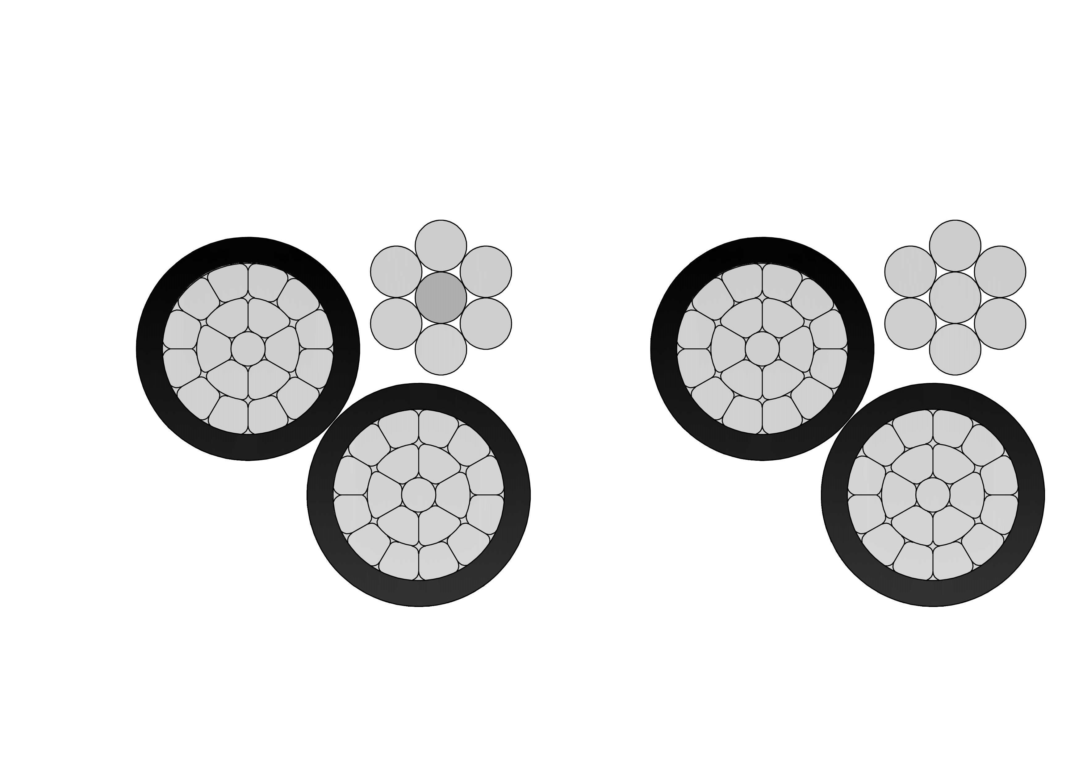
3/0 Aega Aluminum Conductor Triplex Overhead Service Drop Cable
The 3/0 Aega Aluminum Conductor Triplex Overhead Service Drop Cable is designed to deliver safe and efficient overhead power distribution for utility networks. It features two insulated aluminum phase conductors helically wrapped around a bare aluminum neutral messenger, providing strong mechanical support and stable electrical performance. Manufactured using premium aluminum materials and high-performance insulation compounds, the 3/0 Aega Aluminum Conductor Triplex Overhead Service Drop Cable offers excellent resistance to corrosion, UV radiation, and environmental stress. Its optimized construction supports easy handling and installation while meeting utility and industry standards. The cable performs reliably under mechanical load, temperature variation, and long-term outdoor exposure. Strict quality management systems and detailed testing procedures are implemented throughout production to ensure consistent performance and dependable service life.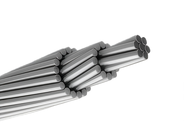
336.4 MCM LINNET ACSR Conductor Cable
The ACSR CAA 336.4 MCM 26/7F LINNET conductor is engineered for superior performance in overhead transmission and distribution systems. Constructed with 26 strands of hard-drawn 1350-H19 aluminium helically stranded around 7 galvanized steel wires, this conductor delivers the perfect balance of high electrical conductivity and enhanced tensile strength. Compliant with ASTM B232 standards, this ACSR conductor is ideal for long-span installations and demanding environmental conditions. The steel-reinforced core, galvanized to Class A or B standards, provides critical mechanical support, while the aluminium strands ensure efficient power transmission. This construction makes the LINNET configuration especially well-suited for medium- to high-voltage lines, where both strength and conductivity are crucial. Its corrosion-resistant steel core enhances durability and reduces maintenance needs, ensuring a long service life in overhead applications.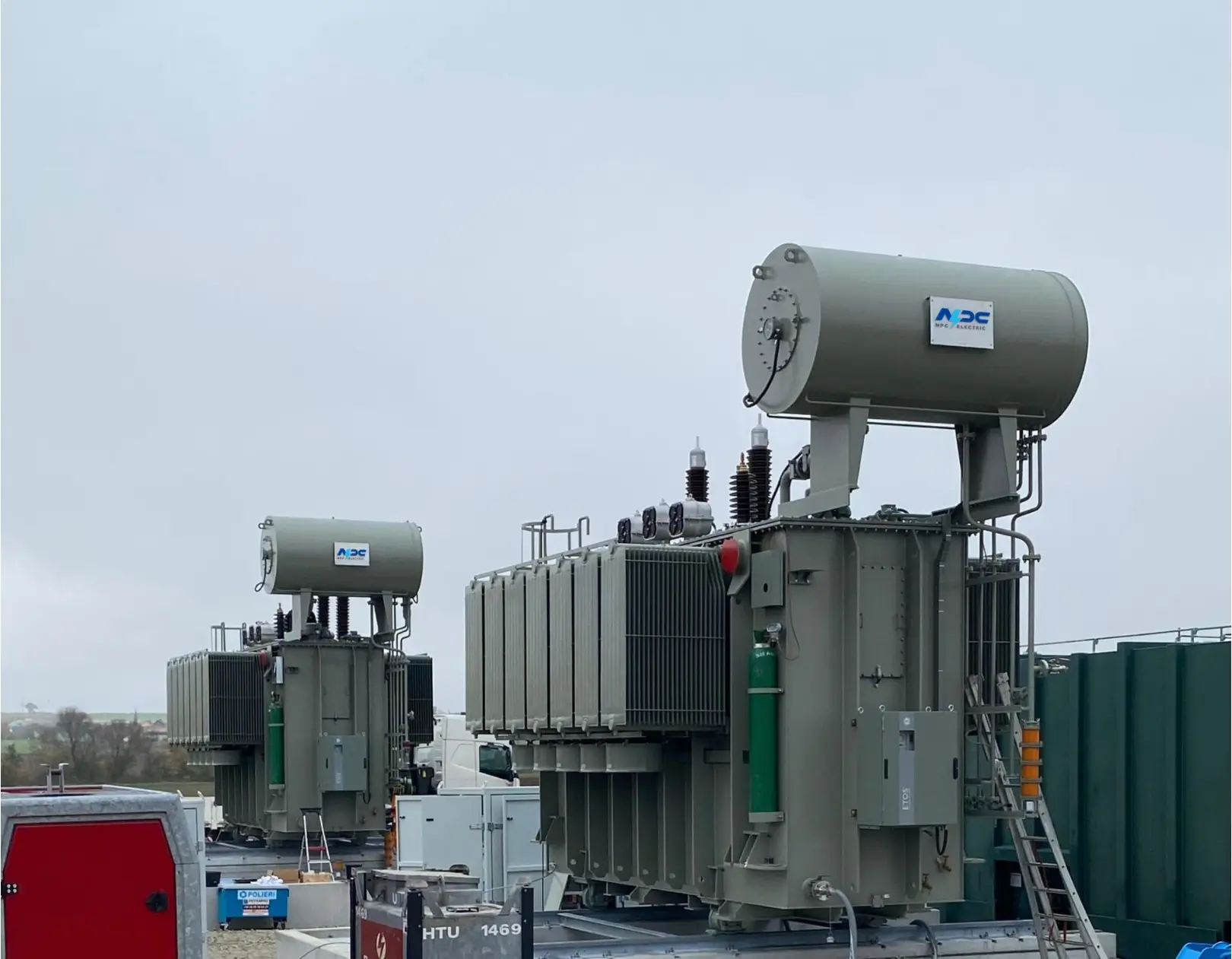
115kV 35MVA Three-Phase Oil-Immersed Power Transformer
The 115kV 35MVA Three-Phase Oil-Immersed Power Transformer is designed for reliable and efficient operation in high-voltage transmission and substation applications. Built with high-permeability silicon steel cores and precision-wound copper conductors, it delivers low losses, strong short-circuit withstand capability, and excellent thermal stability. The oil-immersed cooling system ensures effective heat dissipation, enabling continuous operation under heavy-load conditions. A robust tank structure, advanced insulation system, and outdoor-rated protection make the transformer suitable for harsh environmental conditions. Manufactured in accordance with IEC, IEEE, and ANSI standards, this transformer is widely used in utility substations, industrial power systems, and regional transmission networks where long service life, stable voltage regulation, and high operational reliability are critical.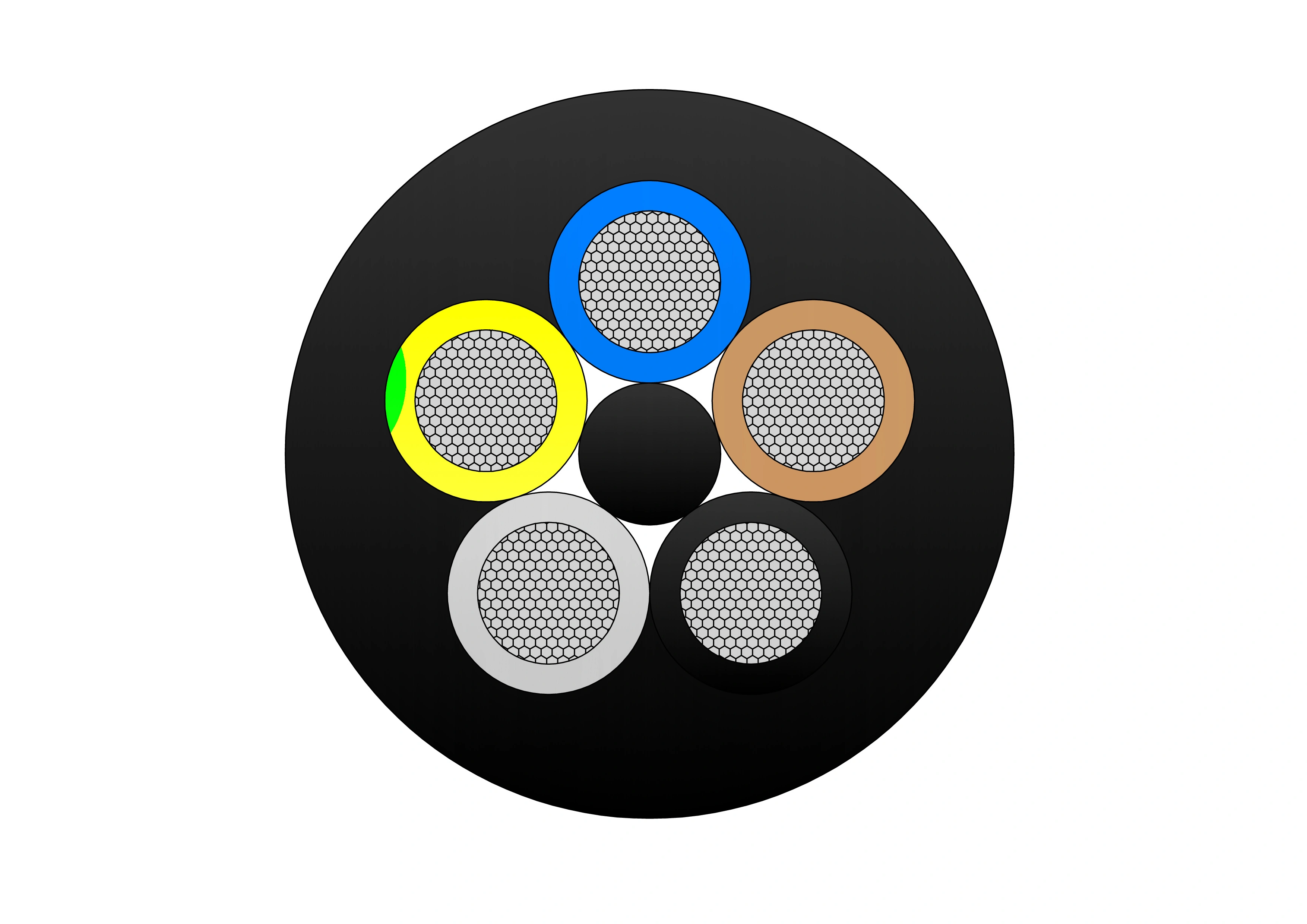
Type 409 Flexible Copper Screened Mining Cable With Central Pilot
The Type 409 Flexible Copper Screened Mining Cable with Central Pilot is a heavy-duty flexible cable engineered for reliable and safe underground mining operations. It features finely stranded tinned copper conductors (class 5) for excellent flexibility and corrosion resistance, EPR (ethylene propylene rubber) insulation for superior dielectric strength and 90°C continuous thermal rating, an overall tinned copper braid screen providing effective EMI protection and grounding, a central pilot core for earth continuity monitoring, safety interlocks, and fault detection, and an extra-heavy-duty flame-retardant rubber outer sheath resistant to oil, abrasion, tearing, crushing, impact, and chemicals. Compliant with AS/NZS 2802 and mining safety standards, it supports high tensile loads, frequent reeling/drag, tight bending radii, and reliable performance in wet, dusty, and hazardous mine conditions. The Type 409 is ideal for power supply to continuous miners, shuttle cars, longwall equipment, drills, and other mobile machinery in coal and metalliferous mines, ensuring enhanced safety through pilot core monitoring and maximum durability.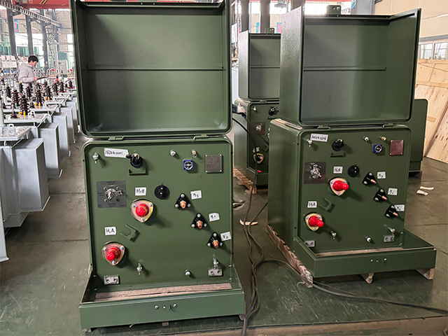
1600kVA Single Phase Pad Mounted Transformer
The 1600kVA Single Phase Pad Mounted Transformer represents the pinnacle of high-capacity underground distribution technology, engineered to handle the most demanding residential and commercial loads with outstanding efficiency and longevity. Conforming to the latest ANSI C57.12.38, IEEE C57.12.00, and DOE 2016/2020 efficiency tiers, this 1600kVA single-phase padmount provides reliable step-down from primary voltages up to 46kV to versatile secondary configurations, supporting massive loop-feed networks with superior overload tolerance and virtually silent operation.
65kV Three-Phase Oil-Immersed Power Transformer with No-Load Voltage Regulation
The 65kV Three-Phase Oil-Immersed Power Transformer with No-Load Voltage Regulation is engineered for medium-to-high voltage distribution systems requiring stable performance and precise voltage control. Equipped with a no-load tap changer, the transformer allows flexible adjustment of voltage ratios to meet varying grid demands. Its high-grade silicon steel core and oxygen-free copper windings ensure low losses, superior thermal efficiency, and long operational life. The oil-immersed cooling system provides enhanced heat dissipation, while the durable outdoor-rated tank structure enables reliable operation in harsh climatic environments. Designed in compliance with IEC, IEEE, and GB standards, this transformer is widely used in utility substations, industrial power networks, renewable energy stations, and large commercial distribution systems. It delivers consistent voltage regulation, strong overload capability, and dependable long-term grid support.
FG7H1OAR - 3.6/6kV, 6/10kV, 8.7/15kV and 12/20kV Cable
The FG7H1OAR - 3.6/6kV, 6/10kV, 8.7/15kV and 12/20kV Cable is a high-quality medium-voltage power cable designed for reliable fixed installations in demanding environments. It features stranded copper or aluminum conductors (class 2), semi-conductive conductor screen, XLPE (cross-linked polyethylene) insulation for excellent dielectric strength and thermal stability (90°C continuous, 250°C short-circuit), semi-conductive insulation screen, copper tape or wire screen for grounding and protection, optional armor (steel tape/wire), and a robust PVC or PE outer sheath resistant to mechanical stress, oils, chemicals, and UV. Compliant with IEC 60502-2 and equivalent standards (e.g., VDE, national codes), it offers low capacitance, high current-carrying capacity, and long service life. Available in single-core or multi-core configurations, the FG7H1OAR is ideal for power distribution in industrial plants, mining facilities, substations, and underground networks where safety, durability, and performance are critical.
LiHCH LSZH Screened Control Cable - 300/500V Halogen-Free Flexible Cable
The LiHCH Control Cable is a halogen-free screened flexible control cable engineered for modern safety-critical applications. It consists of finely stranded copper conductors with LSZH insulation, twisted cores, a tinned copper braid screen for effective EMI protection, and an LSZH outer sheath. This design combines high flexibility, reliable signal transmission, superior fire safety, and minimal smoke and toxic gas emission during combustion. Rated 300/500V, the LiHCH LSZH Screened Control Cable is particularly suitable for public infrastructure, transportation hubs, hospitals, and industrial facilities where fire safety regulations are strict. Manufactured under strict quality control from raw materials to finished product, it meets international standards and provides a safe, reliable solution for control and signal circuits.
600/1000V PVC Insulated Cable to IEC 60502-1 Standard
The 600/1000V PVC Insulated Low Voltage Power Cable is designed for reliable power transmission in low-voltage electrical systems. Manufactured with high-quality copper or aluminum conductors and PVC insulation, this cable provides stable electrical performance, good flexibility, and long service life. The PVC insulation offers effective protection against moisture, abrasion, oils, and common chemicals, making the cable suitable for both indoor and outdoor installations. Rated at 600/1000 volts, the cable ensures safe and efficient power distribution under normal operating conditions. Its robust insulation structure supports consistent current flow while maintaining electrical safety. The cable is easy to install, route, and terminate, making it a practical solution for residential, commercial, and industrial power networks. With dependable insulation performance and mechanical durability, this low voltage power cable meets the demands of everyday electrical infrastructure.
1/0 Murex Aluminum Conductor Triplex Overhead Service Drop Cable
1/0 Murex Aluminum Conductor Triplex Overhead Service Drop Cable is engineered for secondary overhead power distribution from utility lines to residential and light commercial service entrances. The triplex construction consists of two insulated aluminum phase conductors twisted around a bare aluminum neutral messenger, providing both electrical transmission and mechanical support. The 1/0 Murex conductor size offers high current-carrying capacity, excellent tensile strength, and controlled sag performance, making it suitable for longer service drop spans and higher load requirements. Aluminum conductors ensure reduced weight, corrosion resistance, and ease of installation in outdoor environments. Manufactured in accordance with ASTM and utility standards, the 1/0 Murex Aluminum Conductor Triplex Overhead Service Drop Cable delivers consistent electrical performance, long-term durability, and reliable mechanical stability. It is widely used by utilities and contractors seeking a cost-effective and dependable overhead service drop solution.
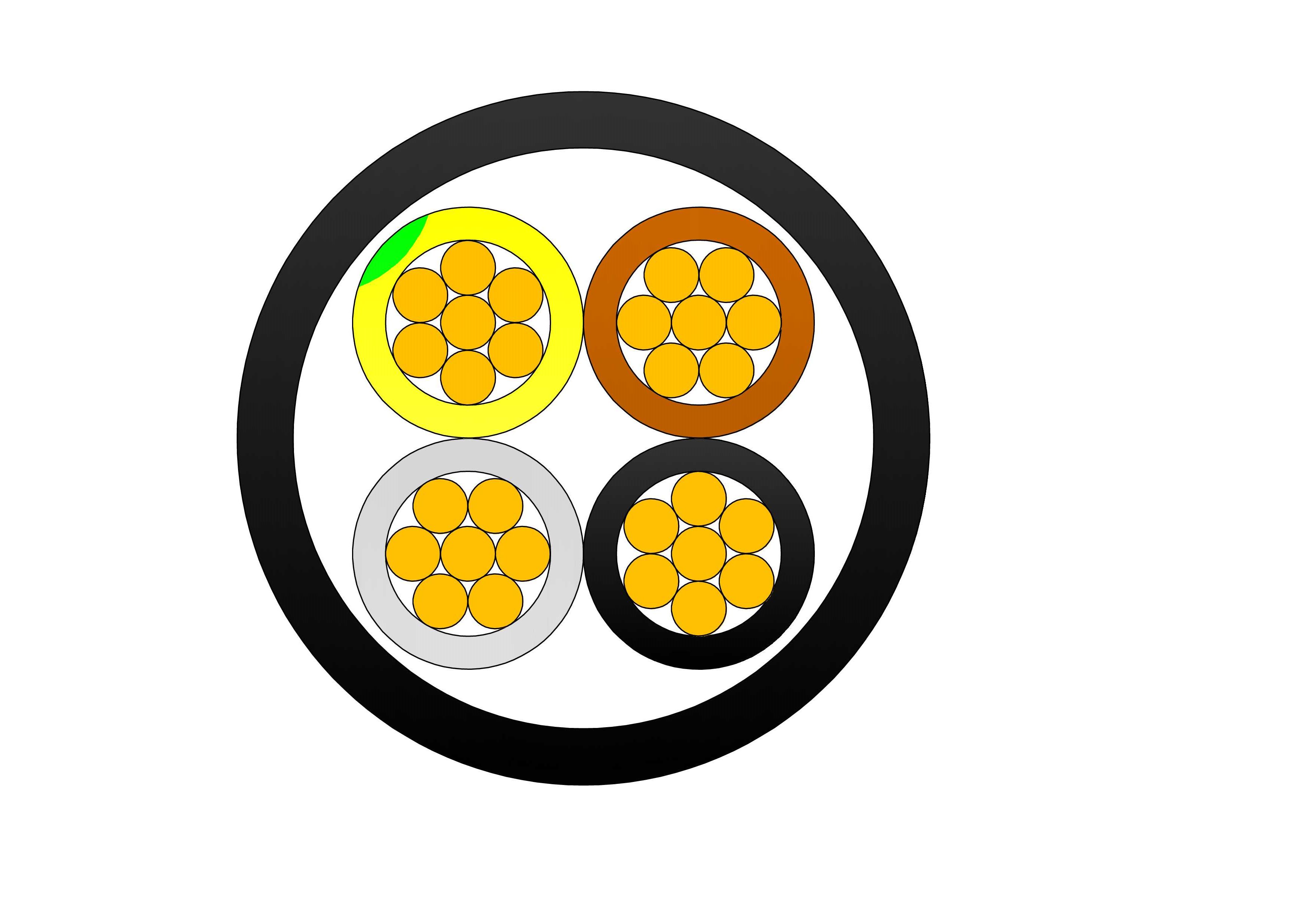
4/5 Cores Copper Cable CU/XLPE/PVC 0.6/1kV
The 4/5 Cores Copper Cable CU/XLPE/PVC 0.6/1kV is engineered for reliable low-voltage power distribution in industrial, commercial, and infrastructure applications. Constructed with high-conductivity stranded copper conductors, premium XLPE insulation, and a durable PVC outer sheath, the cable provides excellent electrical performance, thermal stability, and mechanical protection. The XLPE insulation enables continuous conductor operating temperatures up to 90°C while maintaining outstanding dielectric strength and insulation reliability. The PVC sheath protects against moisture, abrasion, oils, chemicals, and environmental stresses, ensuring long service life in demanding installations. Available in both 4-core and 5-core configurations, the cable is ideal for three-phase power distribution systems, industrial machinery, commercial buildings, utility projects, and electrical networks. Manufactured according to IEC 60502-1 standards, it guarantees safety, efficiency, and dependable performance. Custom conductor sizes, sheath colors, and packaging options are available to meet project-specific requirements. The 4/5 Cores Copper Cable CU/XLPE/PVC 0.6/1kV is a trusted solution for modern electrical infrastructure.
Three Core Medium Voltage Power Cable to IEC 60502
The Three Core Medium Voltage Power Cable to IEC 60502 is designed for stable and efficient power transmission in medium voltage distribution systems. Constructed with three insulated conductors laid together, this cable supports balanced load distribution and compact installation. High-purity copper or aluminum conductors ensure low electrical resistance and reliable current flow. The insulation system, typically based on XLPE, provides excellent dielectric strength, thermal endurance, and resistance to electrical stress. The three-core configuration simplifies installation in substations, industrial plants, and infrastructure projects where space efficiency and system reliability are critical. Manufactured in accordance with IEC 60502, the cable meets international standards for electrical performance, mechanical durability, and operational safety. Its robust construction ensures long service life and dependable operation in demanding medium voltage applications.
2 AWG SPARATE ACSR Conductor Cable
The 2 AWG SPARATE ACSR (Aluminum Conductor Steel Reinforced) cable, compliant with ASTM B232, ABNT NBR 7270/88, and IEC 61089 standards, is engineered for reliable performance in overhead transmission and distribution systems. Featuring a stranded 1350-H19 aluminum conductor for high conductivity and a single galvanized steel core for enhanced mechanical strength, this cable is ideal for medium to long spans in rural, utility, or open-terrain environments. With a voltage rating of up to 25 kV, an operating temperature range of -10°C to +75°C, and a short-circuit tolerance of up to 150°C (5s), the SPARATE ACSR offers an excellent balance of conductivity, tensile strength, and corrosion resistance. Its lightweight, bare aluminum design with a zinc-coated steel core ensures durability and ease of installation, making it suitable for diverse outdoor conditions. Ampacity is calculated under standard conditions (conductor temperature: 75°C; ambient temperature: 25°C; wind speed: 1 m/s; full sun exposure). Manufactured in accordance with ASTM and IEC standards, the 2 AWG SPARATE ACSR Conductor Cable offers stable quality, easy handling, and long service life, making it suitable for utility distribution networks, rural electrification projects, and overhead line upgrades where dependable performance is required.2Y-high-voltage-power-cable-2.webp)
A2XS(FL)2Y MDPE High Voltage 76/132 (145) kV Power Cable
The A2XS(FL)2Y MDPE High Voltage 76/132 (145) kV Power Cable is a single-core aluminum conductor cable with XLPE insulation and MDPE sheath, designed for high-voltage power transmission. Built in accordance with IEC 60840 standards, it provides excellent electrical performance, water resistance, and mechanical protection. Suitable for underground, underwater, indoor, outdoor, and duct installations, the cable features water-blocking tape that prevents water propagation inside, ensuring long-term reliability in power stations, industrial plants, and distribution networks. The A2XS(FL)2Y MDPE is widely used in major UHV transmission grids, underground/submarine lines, river crossings, offshore wind connections, and large-scale renewable energy projects where water ingress protection, efficiency, and ultra-reliability are essential.Welcome your inquiry
Honesty, Integrity, Frugality, Activeness and Passion