How to Design a Dry Type Transformer: Step-by-Step Guide with Design Calculations
2026-03-23
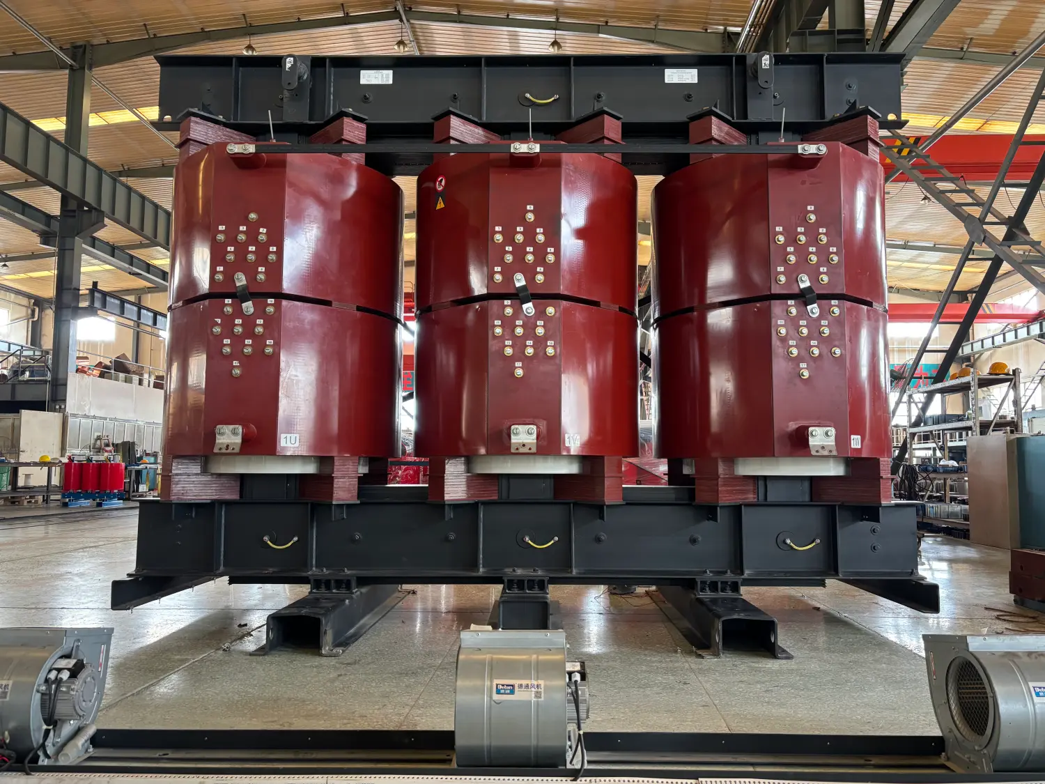
The design of a dry type transformer is a highly integrated multidisciplinary engineering task, encompassing electrical engineering, thermodynamics, mechanical structure, materials science, and safety standards. Unlike traditional oil-immersed transformers, dry type transformers do not rely on mineral oil for insulation and cooling. Instead, they utilize air natural cooling (AN), forced air cooling (AF), or cast resin epoxy systems. This innovative approach provides outstanding advantages such as superior fire resistance, maintenance-free operation, environmental friendliness, and suitability for indoor installations.
During the dry type transformer design process, engineers must precisely calculate electromagnetic parameters for the core and windings to optimize short-circuit impedance, load losses, and no-load losses. Thermal simulations are essential for analyzing temperature rise distribution, enabling the selection of appropriate cooling methods and insulation classes to prevent localized overheating and insulation degradation. Additionally, critical performance indicators—including voltage regulation, noise control, mechanical strength, and short-circuit withstand capability—must comply with national and international standards such as GB/T 1094 or IEC 60076 series.
Leveraging advanced CAD/CAE tools and finite element analysis, modern dry type transformer design achieves higher efficiency, lower operating costs, and extended service life. These transformers are widely applied in high-safety-demand environments like data centers, hospitals, subways, and high-rise buildings.
Step 1: Define Electrical Ratings and Application Conditions
Every transformer design begins with system requirements.
Typical inputs:
- Rated power: 100 kVA – 25 MVA
- Primary voltage: e.g. 11 kV, 22 kV, 33 kV
- Secondary voltage: e.g. 400 V, 690 V
- Frequency: 50 / 60 Hz
- Cooling: AN or AF
- Installation: indoor, confined space, high-rise building
Example: Basic Rating Definition
Assume:
- Rated power: 1000 kVA
- Primary voltage: 11 kV
- Secondary voltage: 415 V
- Frequency: 50 Hz
- Type: Cast resin dry-type transformer
This rating determines current, conductor size, insulation class, and cooling system.
Step 2: Calculate Rated Currents (Primary and Secondary)
Rated current is fundamental to winding and conductor design.
Formula

Example Calculation
Primary current:

Secondary current:

These values drive coil windings' cross-section, current density, and thermal losses.
Step 3: Selection of Dry Type Transformer Type
Based on application:
- Cast resin dry-type transformer → high humidity, high voltage, fire safety
- VPI dry transformer → standard indoor electrical rooms
- Dry-type triplex transformers → rectifier and special industrial loads
For the example above, a cast resin transformer is preferred due to high secondary current and thermal stability requirements.
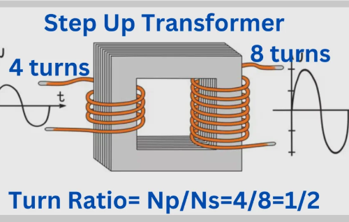
Step 4: Winding Design and Turns Calculation
Turns Ratio

If the LV winding has 40 turns, then:

Current Density Selection
Typical design values:
- Copper windings: 2.5–3.2 A/mm² (dry transformer)
- High reliability designs: lower current density
Secondary conductor cross-section:

Multiple parallel copper strips or foil windings are used to achieve this area.
Step 5: Winding Resistance and Copper Loss Calculation
Formula

Assume:
- Secondary winding resistance = 0.002 Ω

Copper losses are a major contributor to temperature rise, influencing cooling system design.
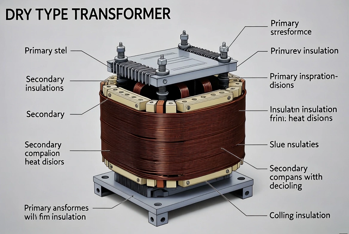
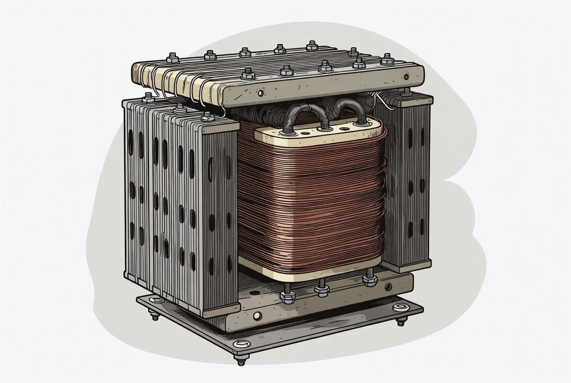
Step 6: Core Design and Magnetic Flux Calculation
EMF Equation

Where:
- BBB = flux density (typically 1.4–1.6 T)
- AAA = core area
Assuming:
- Flux density = 1.5 T
- Frequency = 50 Hz
The core cross-section is selected to keep no-load losses and noise within limits, especially critical in high-rise buildings.
Step 7: Cooling System Design (Air Cooled vs Forced Air)
Dry transformers rely on air cooling, but load and ambient conditions dictate the method.
Temperature Rise Limits
- Class F insulation: 100 K
- Class H insulation: 125 K
Cooling Decision Example
If calculated total losses:
- Core losses: 1.8 kW
- Copper losses: 3.9 kW
- Total losses: 5.7 kW
Natural air cooling may be sufficient up to ~1000 kVA. If overload capacity or confined installation is required, forced air (AF) is added to increase the rating by 25–40%.
Step 8: Short-Circuit Withstand and Mechanical Design
Short-circuit forces are proportional to:

High secondary currents require:
- Rigid coil bracing
- Axial and radial reinforcement
- Strong resin encapsulation (for cast resin transformers)
This ensures compliance with IEC short-circuit withstand requirements.
Step 9: Voltage Regulation Calculation
Approximate Formula

Well-designed dry transformers typically achieve:
- Voltage regulation: 4–6%
Low regulation is essential for sensitive loads and stable output voltage.
Step 10: Industry Standards and Testing
Dry-type transformers must comply with:
- IEC 60076
- IEEE C57
- Local grid and project specifications
Routine and type tests include:
- Winding resistance measurement
- Temperature rise test
- Partial discharge test
- Sound level measurement
Application-Specific Design Considerations
|
Application |
Design Focus |
|
High-rise buildings |
Low noise, compact size |
|
Data centers |
Forced air cooling, redundancy |
|
Renewable energy |
Voltage stability, efficiency |
|
Industrial plants |
Overload capability |
Designing a dry-type transformer is a calculation-driven engineering process that integrates electrical ratings, winding resistance, cooling system performance, and mechanical integrity. By applying correct design calculations at each stage—from rated current to temperature rise—engineers ensure reliable operation, safety, and compliance with industry standards.
For critical infrastructure such as high-rise buildings, industrial facilities, and renewable energy systems, partnering with an experienced dry type transformers manufacturer ensures that theoretical calculations translate into robust, field-proven transformer designs.
Related Articles


Related Products
18 Gauge Galvanized Steel Conductor Wire for Fencing & Binding
The 18 Gauge Galvanized Steel Conductor Wire is designed for flexibility, durability, and reliable performance in light-duty applications. Manufactured from high-quality carbon steel and coated with a protective zinc layer through hot-dip galvanization, it offers excellent resistance to corrosion, rust, and environmental exposure. With its thinner 18 gauge diameter, this wire provides superior flexibility while maintaining adequate tensile strength, making it ideal for applications such as agricultural fencing, construction binding, packaging, and general industrial use. The uniform zinc coating ensures long-lasting protection, even in outdoor and humid environments. The smooth and clean surface reduces friction during handling and installation, improving efficiency and safety. Produced under strict quality control procedures and compliant with international standards such as ASTM and IEC, the wire ensures consistent performance. Customization options including zinc coating thickness, tensile strength, and packaging are available to meet specific customer requirements, making it a cost-effective and versatile solution.
NTSCGECECWOU 8.7/15kV and 12/20kV Cable
NTSCGECECWOU 8.7/15kV and 12/20kV cable is a flexible medium voltage power cable manufactured according to DIN VDE 0250 standards, engineered for heavy-duty energy supply in mining, tunneling, and mobile equipment applications. Featuring Class 5 tinned copper conductors, EPR insulation, a halogen-free flame-retardant sheath, and concentric copper conductors for EMC protection, it ensures outstanding mechanical strength, oil and moisture resistance, and fire safety. Designed for reeling drum systems and mobile machinery, it is ideal for both indoor and outdoor use in harsh, demanding environments.
NTSCGECEWOU 3.6/6kV, 6/10kV, 8.7/15kV and 12/20kV Cable
The NTSCGECEWOU 3.6/6kV, 6/10kV, 8.7/15kV and 12/20kV Cable is a flexible, heavy-duty medium-voltage trailing/reeling cable designed for demanding mining and tunnelling operations. It features class 5 finely stranded tinned copper phase conductors for superior flexibility and corrosion resistance, semi-conductive conductor and insulation screens for field control, EPR (ethylene propylene rubber) insulation providing high dielectric strength and 90°C continuous operation, individual copper wire screens serving as earth conductors, control conductors, a monitoring conductor (ÜL), and a robust rubber outer sheath resistant to oil, flame, abrasion, tearing, and mechanical stress. Compliant with DIN VDE 0250, it supports high tensile loads, fast reeling speeds, tight bending radii, and effective EMC shielding across voltage ranges. The NTSCGECEWOU ensures safe, reliable MV power supply to mobile equipment such as shearers, tunnel boring machines, and conveyors in harsh underground and opencast environments, minimising downtime and enhancing operational efficiency.
2 Conch Aluminum Conductor Triplex Overhead Service Drop Cable
The 2-2-2 Conch Aluminum Conductor Triplex Overhead Service Drop Cable is a trusted solution for overhead power distribution from utility poles to residential or commercial weatherheads. Featuring concentric-lay-stranded 1350-H19 aluminum phase conductors (#2 AWG, 7-strand), durable black cross-linked polyethylene (XLPE) insulation, and a bare ACSR neutral messenger (#2 AWG, 6/1), it provides excellent electrical conductivity, superior weather/UV resistance, and mechanical support. Rated for 600 volts phase-to-phase with conductor temperatures up to 90°C (XLPE), it delivers an allowable ampacity of approximately 150 amps. Compliant with ASTM B-230, B-231, B-232, B-399, and ICEA S-76-474 standards, this lightweight, flexible cable ensures easy installation and long-term reliability in harsh outdoor environments, including wind, ice loading, and temperature fluctuations.
2 AWG SPARATE ACSR Conductor Cable
The 2 AWG SPARATE ACSR (Aluminum Conductor Steel Reinforced) cable, compliant with ASTM B232, ABNT NBR 7270/88, and IEC 61089 standards, is engineered for reliable performance in overhead transmission and distribution systems. Featuring a stranded 1350-H19 aluminum conductor for high conductivity and a single galvanized steel core for enhanced mechanical strength, this cable is ideal for medium to long spans in rural, utility, or open-terrain environments. With a voltage rating of up to 25 kV, an operating temperature range of -10°C to +75°C, and a short-circuit tolerance of up to 150°C (5s), the SPARATE ACSR offers an excellent balance of conductivity, tensile strength, and corrosion resistance. Its lightweight, bare aluminum design with a zinc-coated steel core ensures durability and ease of installation, making it suitable for diverse outdoor conditions. Ampacity is calculated under standard conditions (conductor temperature: 75°C; ambient temperature: 25°C; wind speed: 1 m/s; full sun exposure). Manufactured in accordance with ASTM and IEC standards, the 2 AWG SPARATE ACSR Conductor Cable offers stable quality, easy handling, and long service life, making it suitable for utility distribution networks, rural electrification projects, and overhead line upgrades where dependable performance is required.
(N)TSCGECECWOU 3.6/6kV and 6/10kV ZH Cable
The (N)TSCGECECWOU is a flexible medium voltage reeling and trailing cable manufactured in compliance with DIN VDE 0250 standards. Designed for demanding mining, tunneling, and heavy industrial applications, it offers exceptional mechanical strength, flexibility, fire safety, and electromagnetic compatibility (EMC). The cable features EPR insulation, low smoke zero halogen (LSZH) inner sheath, halogen-free polyurethane (PUR) outer sheath, and a copper wire braid with concentric conductor for enhanced shielding and durability. Its design ensures reliable performance in environments requiring fire safety, oil resistance, and high torsional strength.
75kV 1250kVA Three Phase Oil Immersed Power Transformer Copper
The 75kV 1250kVA Three Phase Oil Immersed Power Transformer Copper is engineered for regional 66–75 kV transmission and industrial step-down applications. It adopts 99.99 % electrolytic copper windings, high-grade grain-oriented silicon steel S13 core, corrugated tank + ONAN cooling, and ±5 % off-circuit tap changer (on-load optional). Fully compliant with IEC 60076, lightning impulse withstand 350 kV peak, PD <10 pC, noise ≤58 dB. Fully sealed or conservator design with vacuum oil filling and nitrogen sealing ensures >30-year maintenance-free operation even in high-altitude or polluted areas. Ideal for mining, metallurgy, wind farms, and urban 75 kV substations requiring high reliability and low loss.
GYTA53 Fiber Optic Cable
The GYTA53 Fiber Optic Cable is a high-strength outdoor communication cable specifically designed for direct burial applications and harsh installation environments. The cable features a stranded loose tube structure, central strength member, water-blocking system, aluminum polyethylene laminated tape (APL), corrugated steel tape armor (PSP), and double polyethylene outer jackets for maximum mechanical protection. Optical fibers are housed within gel-filled loose tubes that provide excellent moisture resistance and protection against external stress. The combination of aluminum tape and steel tape armor significantly enhances crush resistance, impact resistance, rodent protection, and moisture barrier performance. The dual PE sheath structure further improves environmental durability and long-term reliability. Manufactured according to IEC 60794 and ITU-T standards, the GYTA53 Fiber Optic Cable offers low attenuation, stable transmission performance, and excellent protection in underground installations. It is widely used in long-distance telecommunications networks, backbone communication systems, utility networks, and infrastructure projects requiring direct burial deployment.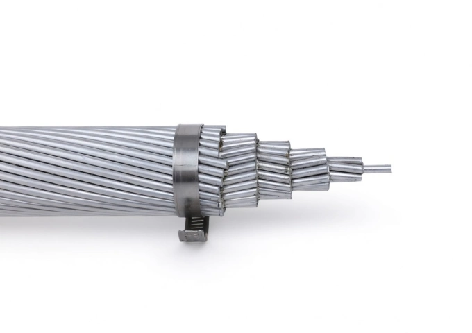
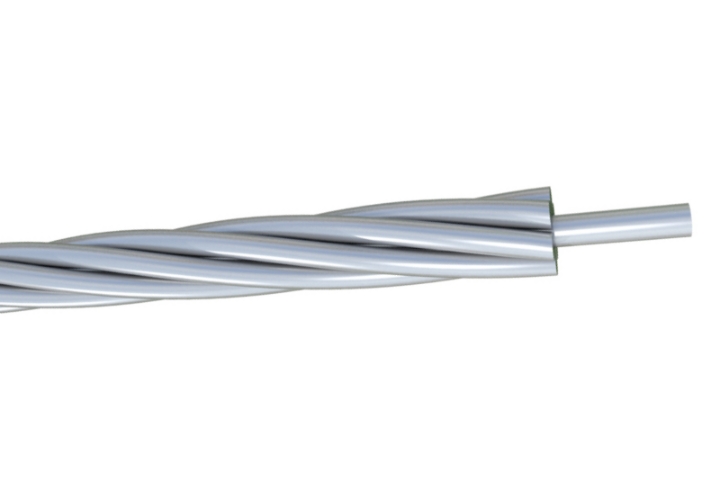
477 MCM Syringa AAC Cable
The 477 MCM Syringa AAC Cable is a high-performance All Aluminum Conductor designed for demanding overhead power transmission and distribution lines. Manufactured with 37 strands of premium 1350-H19 aluminum wire in a concentric lay configuration, this bare conductor provides excellent electrical conductivity with a low DC resistance of 0.0362 ohms per 1000 ft at 20°C. Featuring an overall diameter of 0.795 inches and a rated breaking strength of 8,690 lbs, the Syringa AAC delivers a robust ampacity of 639 amps while weighing only 447.8 lbs per 1000 ft. Its optimized strength-to-weight ratio minimizes sag and structural loading. Fully compliant with ASTM B-230 and B-231 standards, the 477 MCM Syringa AAC Cable offers outstanding corrosion resistance for long-term durability in harsh outdoor environments, making it the preferred choice for utility networks requiring cost-effective, high-reliability bare aluminum conductors.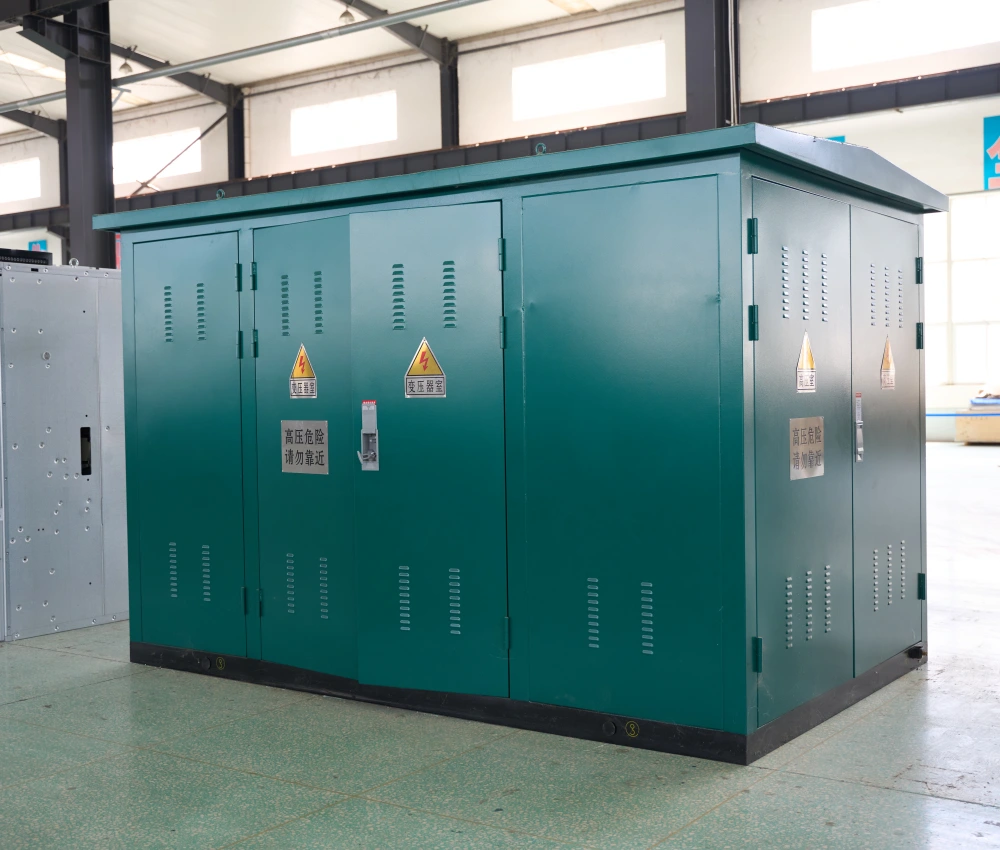
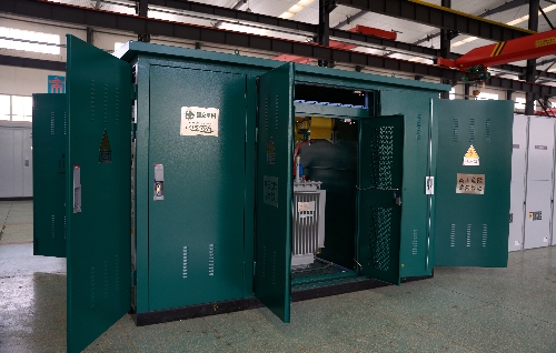
Outdoor Prefabricated Transformer Substation
The Outdoor Prefabricated Transformer Substation is an integrated medium-voltage power distribution solution designed for outdoor installation in industrial, commercial, utility, and renewable energy applications. The system combines medium-voltage switchgear, distribution transformer, low-voltage distribution equipment, and intelligent control systems into a compact prefabricated enclosure, providing efficient and reliable power transformation while minimizing construction time and installation costs. Engineered for harsh environmental conditions, the outdoor substation features a weather-resistant enclosure, corrosion-protected structure, advanced insulation technology, and optimized thermal ventilation system to ensure long-term operational stability. Its modular design allows rapid deployment, simplified transportation, and flexible installation while improving maintenance accessibility and operational safety. The Outdoor Prefabricated Transformer Substation supports multiple voltage levels, transformer capacities, and intelligent automation functions, making it suitable for utility distribution systems, renewable energy projects, urban infrastructure, mining facilities, transportation networks, and industrial manufacturing plants. With smart-grid compatibility and customizable configurations, the substation provides efficient and scalable electrical distribution performance for modern power networks.
8 Gauge Galvanized Steel Conductor Wire
The 8 Gauge Galvanized Steel Conductor Wire is engineered for demanding utility applications, delivering reliable high-strength performance with outstanding corrosion resistance. Produced with heavy hot-dip galvanizing, this 8 AWG wire features a uniform zinc coating that effectively protects against rust in challenging environments. It performs exceptionally well as overhead ground wire, static wire, or guy wire for pole guying in power transmission and distribution systems. Meeting ASTM A475 requirements, the 8 Gauge Galvanized Steel Conductor Wire provides excellent tensile strength and long service life with minimal maintenance. Rigorous quality testing throughout production ensures consistent mechanical properties and coating integrity, making it a cost-effective and dependable solution for shielding and structural support in overhead lines.
230kV 3-Phase Step-Down Power Transformer
The 230kV 3-Phase Step-Down Power Transformer is designed to reduce high transmission voltages to suitable distribution levels while maintaining excellent efficiency and operational stability. Engineered for utility substations and large-scale grid interfaces, this transformer ensures safe and controlled power delivery from high-voltage networks to regional or industrial distribution systems. Its oil-immersed insulation system provides strong dielectric protection and efficient thermal dissipation, enabling reliable continuous operation under varying load conditions. Precision core construction and optimized winding layout help minimize energy losses and voltage fluctuation. The transformer’s robust mechanical design enhances resistance to short-circuit forces and thermal stress, supporting long service life and low maintenance. This solution is ideal for modern power grids requiring dependable voltage transformation and efficient energy management.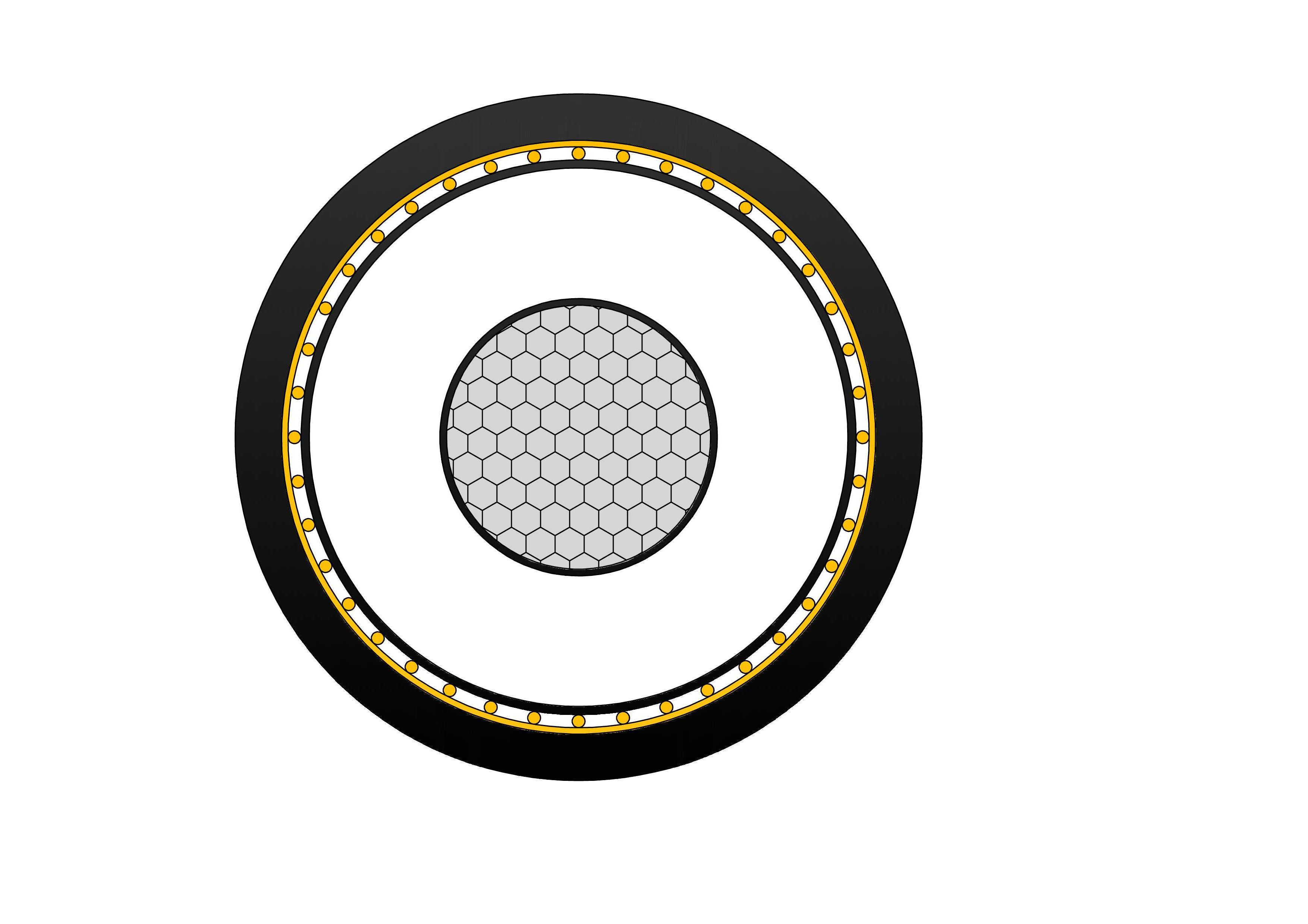
N2XSH Medium Voltage Power Cable(6/10kV, 12/20kV, 18/30kV)
N2XSH are flame-retardant, low smoke, zero halogen (LSZH) medium voltage cables with copper conductors, manufactured according to IEC 60502-2 standards. Featuring stranded copper conductors, cross-linked polyethylene (XLPE) insulation, copper tape or wire screen, and low smoke zero halogen (LSZH) outer sheath, it complies with IEC 60502-2 and fire performance standards. In fire situations, the LSZH sheath emits minimal smoke and no toxic halogen gases, protecting lives and equipment. Excellent electrical properties, low dielectric losses, and high thermal stability ensure efficient power transmission. Suitable for direct burial, ducts, or indoor installations in public areas, it offers good mechanical protection and moisture resistance. The N2XSH Medium Voltage Power Cable is the preferred choice for utilities, hospitals, schools, tunnels, and infrastructure projects demanding reliable, environmentally friendly medium voltage cabling with superior fire safety and long service life worldwide.
11kV Oil Immersed Transformer
The 11kV Oil Immersed Transformer is a robust, three-phase medium-voltage distribution unit optimized for efficient step-down power delivery in 50/60Hz AC networks. Engineered with a hermetically sealed tank featuring corrugated fins for thermal expansion compensation, it eliminates conservator requirements while offering superior moisture protection and extended operational durability. High-grade cold-rolled grain-oriented silicon steel laminations reduce core losses significantly, paired with low-resistance copper or aluminum windings for minimized load losses and enhanced conductivity.
1113 MCM Marigold AAC Cable
The 1113 MCM Marigold AAC Cable is a high-performance All Aluminum Conductor designed for demanding overhead power transmission and distribution lines. Manufactured with 37 strands of premium 1350-H19 aluminum wire in a concentric lay configuration, this bare conductor provides excellent electrical conductivity with a low DC resistance of 0.0155 ohms per 1000 ft at 20°C. Featuring an overall diameter of 1.216 inches and a rated breaking strength of 19,300 lbs, the Marigold AAC delivers a robust ampacity of 1083 amps while weighing only 1045.4 lbs per 1000 ft. Its optimized strength-to-weight ratio minimizes sag and structural loading. Fully compliant with ASTM B-230 and B-231 standards, the 1113 MCM Marigold AAC Cable offers outstanding corrosion resistance for long-term durability in harsh outdoor environments, making it the preferred choice for utility networks requiring cost-effective, high-reliability bare aluminum conductors.Welcome your inquiry
Honesty, Integrity, Frugality, Activeness and Passion