Solar Cable Guide: Types, Specs, Installation & Safety Tips
2026-08-12
As global demand for renewable energy continues to grow, solar energy systems have become a cornerstone of sustainable power generation. While solar panels often receive the most attention, the performance, efficiency, and safety of any solar power system depend heavily on one critical component: the solar cable.
Solar cables serve as the electrical pathway connecting solar panels, inverters, batteries, charge controllers, grounding systems, and other essential components. Improper cable selection can result in power losses, overheating, reduced system lifespan, and safety hazards. Conversely, properly engineered solar wiring ensures reliable energy transmission, long-term durability, and compliance with international standards.
1. Understanding the Role of Solar Cables in Solar Energy Systems
A solar cable is a specialized electrical conductor designed to withstand the demanding environmental conditions associated with photovoltaic (PV) installations.
Unlike conventional electrical cords, solar cables must endure:
- Continuous UV exposure
- Extreme temperature variations
- Moisture and humidity
- Mechanical stress
- Ozone exposure
- Chemical contamination
In a typical solar power system, cables perform multiple functions:
Power Transmission
Solar cables transfer electricity from solar panels to inverters and energy storage systems.
System Interconnection
They connect panels and other components within the photovoltaic array.
Grounding Protection
Specialized solar ground cable products provide fault current paths and improve electrical safety.
Battery Integration
Solar battery cables facilitate reliable power transfer between batteries, charge controllers, and inverters.
Because solar installations often operate outdoors for more than 25 years, cable reliability directly affects project performance and lifecycle cost.
2. Types of Solar Cables and Their Applications
Understanding the different types of solar cables is essential when designing efficient solar energy systems.
DC Solar Cables
DC solar cables connect photovoltaic modules and carry direct current generated by solar panels.
Key characteristics include:
- Double insulation
- UV resistance
- Flame retardancy
- Ozone resistance
- High-temperature tolerance
These cables are specifically engineered for outdoor solar installations.
AC Solar Cables
After power is converted by the inverter, AC cables transmit electricity to electrical panels or utility interconnection points.
AC cables must comply with local electrical codes and voltage requirements.
Solar Panel Extension Cable
A solar panel extension cable is commonly used when the distance between solar modules and other equipment exceeds standard cable lengths.
Applications include:
- Rooftop systems
- Ground-mounted arrays
- Portable solar systems
- Off-grid installations
Solar Battery Cables
Solar battery cables connect battery banks to inverters and charge controllers.
These cables typically require:
- Larger conductor sizes
- Low resistance
- Flexible construction
- High current-carrying capacity
Solar Ground Cable
Grounding conductors provide personnel protection and equipment safety during fault conditions.
Proper grounding is mandatory in most international electrical standards.
Table: Technical Comparison of Solar Cable Types
|
Cable Type |
Typical Voltage Rating |
Main Application |
Key Advantages |
|
DC Solar Cable |
1000V / 1500V DC |
PV module interconnection |
UV-resistant, weatherproof, low loss |
|
AC Solar Cable |
600V / 1000V AC |
Inverter to grid connection |
High current capacity, code compliant |
|
Solar Panel Extension Cable |
1000V / 1500V DC |
Extended panel connections |
Flexible installation, easy expansion |
|
Solar Battery Cable |
600V – 1000V DC |
Battery energy storage systems |
High current carrying capability |
|
Solar Ground Cable |
600V |
Grounding and bonding systems |
Enhanced safety and fault protection |
|
Portable Solar Cable |
600V – 1000V DC |
Mobile solar kits and RV systems |
Lightweight and flexible |
|
MC4 Connector Cable Assembly |
1500V DC |
Plug-and-play solar installations |
Fast deployment and secure connections |
Engineering Insight
Selecting the correct cable type depends on system architecture. DC solar cables are optimized for photovoltaic strings, while solar battery cables are engineered for higher current flow. Grounding conductors remain essential for personnel safety and equipment protection.
3. Solar Cable Specifications and Performance Requirements
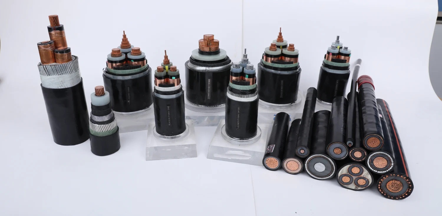
Solar cable performance is determined by several critical technical specifications.
Conductor Material
Most high-quality solar power cable products use:
- Tinned copper conductors
- Bare copper conductors
- Flexible stranded conductors
Tinned copper is preferred because it provides superior corrosion resistance in outdoor environments.
Insulation Material
Premium solar cables utilize:
- XLPO (Cross-linked Polyolefin)
- XLPE (Cross-linked Polyethylene)
- Halogen-free compounds
These materials improve thermal stability and fire safety.
Voltage Rating
Typical voltage ratings include:
- 600 V
- 1000 V
- 1500 V
Modern utility-scale projects increasingly adopt 1500V systems to improve efficiency and reduce installation costs.
Temperature Rating
High-quality solar cables typically operate within:
-40°C to +90°C
with short-term temperature resistance exceeding 120°C.
International Standards
Common standards include:
- IEC 62930
- EN 50618
- TÜV 2 PfG 1169
- UL 4703
Compliance with these standards ensures product reliability and global market acceptance.
Table: International Standards for Solar Cables
|
Standard |
Region |
Scope |
|
IEC 62930 |
Global |
Photovoltaic DC cable requirements |
|
EN 50618 |
Europe |
H1Z2Z2-K solar cable specification |
|
TÜV 2 PfG 1169 |
Europe |
PV cable certification |
|
UL 4703 |
North America |
Photovoltaic wire requirements |
|
NEC Article 690 |
USA |
Solar installation regulations |
|
IEC 60364 |
International |
Electrical installation standards |
|
IEC 60228 |
International |
Conductor classification |
|
RoHS Compliance |
Global |
Environmental protection requirements |
Engineering Insight
For international EPC projects and export-oriented solar cable manufacturers, compliance with IEC 62930, EN 50618, and UL 4703 significantly improves market acceptance and facilitates certification across multiple regions.
4. Solar Cable Size Selection and Voltage Drop Considerations
One of the most common design errors in solar installations involves improper cable sizing.
Cable size affects:
- Voltage drop
- Energy efficiency
- Heat generation
- Safety
- System performance
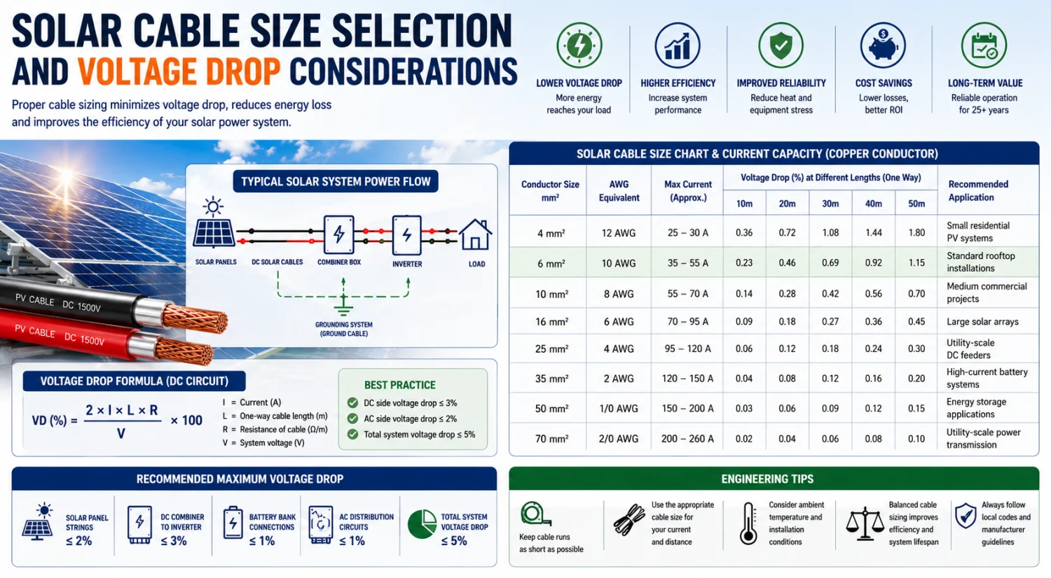
Engineering Solar Cable Size Chart
|
Conductor Size |
AWG Equivalent |
Max Current (Approx.) |
Recommended Solar Application |
|
4 mm² |
12 AWG |
25–30 A |
Small residential PV systems |
|
6 mm² |
10 AWG |
35–55 A |
Standard rooftop solar installations |
|
10 mm² |
8 AWG |
55–70 A |
Medium commercial projects |
|
16 mm² |
6 AWG |
70–95 A |
Large solar arrays |
|
25 mm² |
4 AWG |
95–120 A |
Utility-scale DC feeders |
|
35 mm² |
2 AWG |
120–150 A |
High-current battery systems |
|
50 mm² |
1/0 AWG |
150–200 A |
Energy storage applications |
|
70 mm² |
2/0 AWG |
200–260 A |
Utility-scale power transmission |
Recommended Maximum Voltage Drop
|
System Section |
Recommended Voltage Drop |
|
Solar Panel Strings |
≤ 2% |
|
DC Combiner to Inverter |
≤ 3% |
|
Battery Bank Connections |
≤ 1% |
|
AC Distribution Circuits |
≤ 2% |
|
Total System Voltage Drop |
≤ 5% |
Engineering Insight
Reducing voltage drop directly increases energy yield. In large solar farms, a 1% reduction in cable losses can translate into significant lifetime energy gains and improved project ROI.
6mm Solar Cable
The 6mm solar cable is one of the most commonly used conductor sizes for residential rooftop installations.
Advantages include:
- Low voltage drop
- Easy installation
- Cost efficiency
10 AWG Solar Cable
A 10 AWG solar cable is widely used in small-to-medium solar arrays and battery connections.
8 AWG Solar Cable
An 8 AWG solar cable is suitable for longer cable runs and higher current applications.
Voltage Drop Best Practice
Industry best practice recommends:
- DC side voltage drop ≤ 3%
- AC side voltage drop ≤ 2%
Reducing voltage drop improves energy production and overall system efficiency.
5. Cable Selection for Residential and Commercial Solar Projects
The ideal cable selection depends on project size, electrical load, environmental conditions, and installation method.
Residential Solar Installations
Homes or businesses operating rooftop solar systems typically require:
- 4 mm² to 6 mm² PV cables
- UV-resistant insulation
- MC4-compatible connectors
The focus is often on balancing performance and installation cost.
Commercial Solar Projects
Commercial systems generally involve:
- Longer cable runs
- Higher string voltages
- Larger current loads
These applications frequently require:
- 10 AWG solar cable
- 8 AWG solar cable
- Larger battery cables
Utility-Scale Solar Farms
Utility-scale projects prioritize:
- Energy efficiency
- Reduced voltage drop
- Long-term durability
Engineering teams typically conduct detailed cable calculations to optimize project economics and system performance.
6. Installation Best Practices for Solar Cables
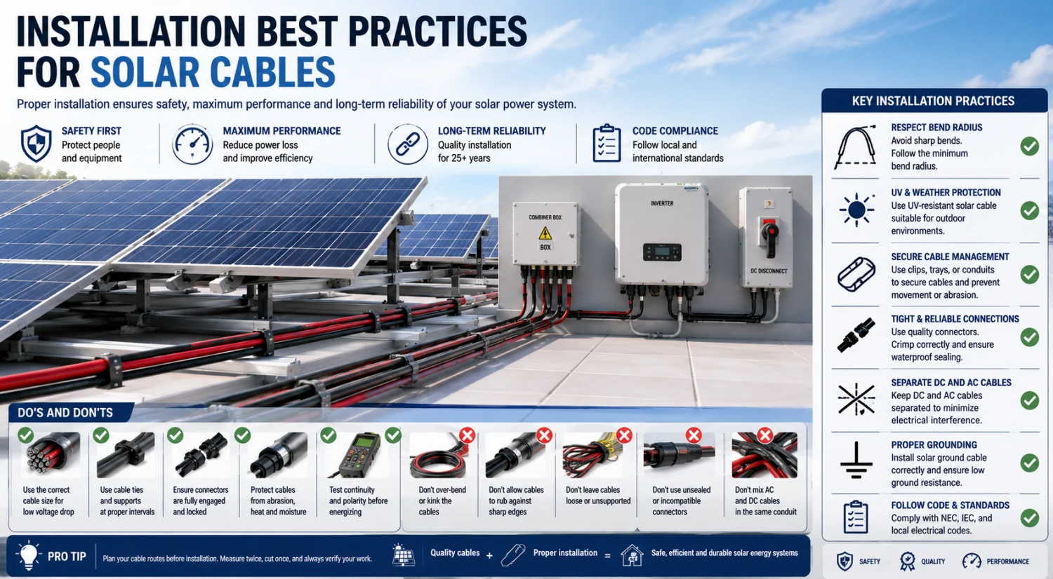
Proper installation is just as important as cable selection.
Poor workmanship can compromise even the highest-quality solar cable.
Cable Routing
Installers should:
- Avoid sharp bends
- Maintain proper bend radius
- Minimize cable stress
- Prevent mechanical damage
Environmental Protection
Solar cables should be protected from:
- Abrasion
- Rodent damage
- Standing water
- Excessive heat sources
Connector Integrity
Poor connections are a leading cause of solar system failures.
Best practices include:
- Using certified connectors
- Proper crimping techniques
- Torque verification
- Moisture sealing
Cable Management
Professional cable management improves:
- Safety
- Maintenance accessibility
- System aesthetics
- Long-term reliability
Cable trays, conduits, and UV-resistant ties should be used whenever appropriate.
7. Safety Tips for Long-Term Solar System Reliability
Electrical safety remains a critical consideration throughout the lifecycle of solar energy systems.
Prevent Overheating
Undersized conductors can create excessive heat and insulation damage.
Always select cables based on:
- Current capacity
- Ambient temperature
- Installation method
Inspect Regularly
Routine inspections should verify:
- Cable integrity
- Connector condition
- Insulation performance
- Grounding continuity
Protect Against UV Degradation
Only certified solar cables should be used in exposed outdoor environments.
Conventional electrical cords may deteriorate rapidly when exposed to sunlight.
Follow Electrical Codes
Compliance with local electrical regulations ensures:
- Personnel safety
- Insurance compliance
- Utility acceptance
Grounding and Bonding
A properly installed solar ground cable system minimizes electrical shock hazards and improves system fault protection.
Table: Recommended Solar Cable Inspection Schedule
|
Inspection Item |
Monthly |
Quarterly |
Annually |
Purpose |
|
Visual Cable Inspection |
✓ |
✓ |
✓ |
Detect physical damage |
|
Connector Condition Check |
✓ |
✓ |
✓ |
Prevent loose connections |
|
MC4 Connection Verification |
— |
✓ |
✓ |
Ensure low resistance contacts |
|
Cable Clamp Inspection |
— |
✓ |
✓ |
Prevent cable movement |
|
Insulation Resistance Test |
— |
— |
✓ |
Verify insulation integrity |
|
Ground Continuity Test |
— |
✓ |
✓ |
Confirm grounding effectiveness |
|
Thermal Imaging Inspection |
— |
✓ |
✓ |
Identify hot spots |
|
Battery Cable Inspection |
✓ |
✓ |
✓ |
Detect overheating or corrosion |
|
UV Degradation Assessment |
— |
— |
✓ |
Evaluate outdoor exposure effects |
|
Voltage Drop Measurement |
— |
— |
✓ |
Confirm system efficiency |
|
Junction Box Inspection |
— |
✓ |
✓ |
Prevent moisture ingress |
|
Documentation Review |
— |
— |
✓ |
Maintain compliance records |
Engineering Insight
Industry studies indicate that over 30% of solar system failures originate from wiring, connectors, or termination issues rather than photovoltaic modules. A structured cable inspection program can significantly reduce downtime and improve long-term system reliability.
8. Future Trends in Solar Cable Technology
As solar installations continue to expand globally, cable technology is evolving to support higher system voltages, larger power capacities, and improved reliability.
Emerging developments include:
Higher Voltage Systems
1500V solar arrays are becoming standard in large-scale projects.
Smart Monitoring Integration
Advanced cables may incorporate monitoring technologies capable of detecting:
- Temperature changes
- Insulation degradation
- Fault conditions
Enhanced Fire Resistance
New insulation materials provide improved fire performance and environmental sustainability.
Sustainable Manufacturing
Manufacturers increasingly adopt recyclable materials and environmentally responsible production processes.
As solar energy systems become more sophisticated, cable technology will play an increasingly important role in maximizing efficiency, safety, and project profitability.
Conclusion
Selecting the right solar cable is one of the most important decisions in any photovoltaic project. Whether designing a residential rooftop system, a commercial solar installation, or a utility-scale solar farm, engineers and installers must carefully evaluate cable type, conductor size, insulation quality, voltage rating, and environmental performance.
From DC solar cables and solar panel extension cable assemblies to solar battery cables and solar ground cable systems, every connection influences the efficiency and reliability of the overall solar power system. By applying proper sizing practices, following installation best practices, and implementing effective safety measures, project owners can maximize energy production while ensuring decades of reliable operation.
In modern solar energy systems, cables are far more than simple conductors—they are critical infrastructure that enables safe, efficient, and sustainable power generation.

Related Articles
Related Products
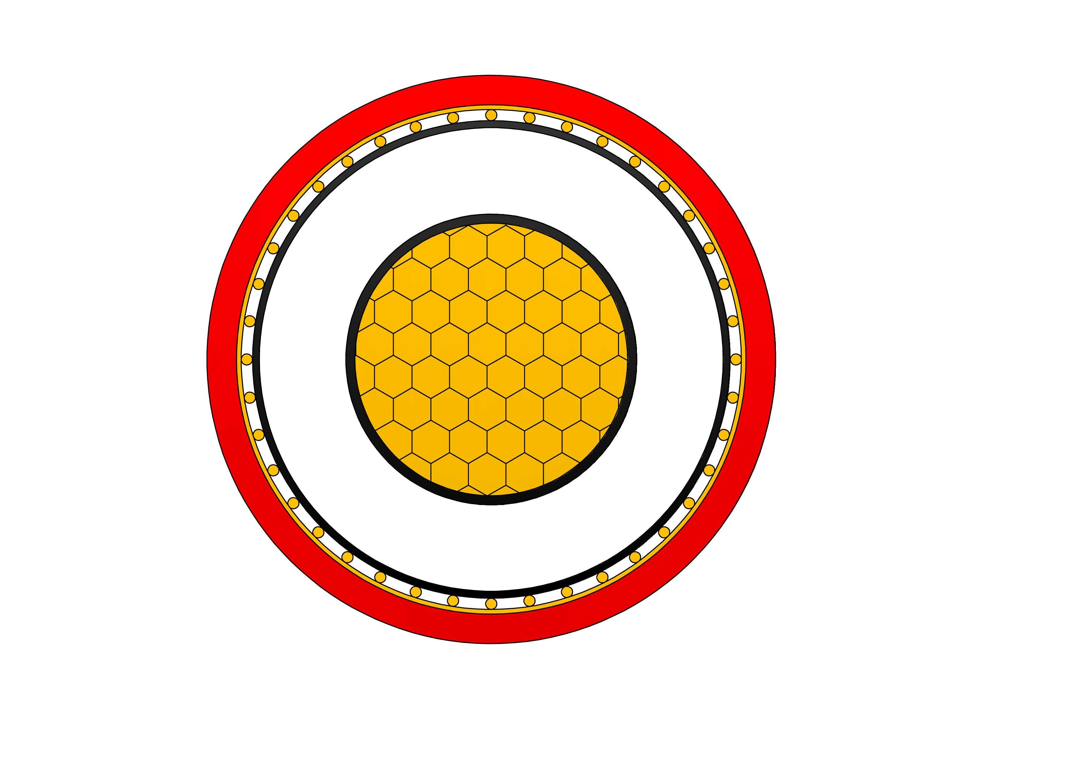
N2XSEY Medium Voltage Power Cable(6/10kV, 8.7/15KV,12/20kV, 18/30kV)
N2XSEY are medium voltage power cables with copper conductors, XLPE insulation, and PVC outer sheath, designed in accordance with VDE 0276-620 standards. Built with copper conductors, thermosetting XLPE insulation, individual metallic screens (copper tape/wire) per core, filler, and tough PVC outer sheath, it meets IEC 60502-2 requirements. Per-core screening minimizes interference and provides fault protection. Low tan delta, high breakdown strength, and excellent thermal endurance ensure efficient operation with reduced losses. PVC sheath delivers good mechanical and moisture protection for fixed installations. Optional longitudinal water-blocking enhances performance in wet conditions. Flame-retardant and durable, the N2XSEY Medium Voltage Power Cable is favored for power grids, industrial sites, renewable installations, and urban infrastructure demanding reliable three-core medium voltage cabling with superior shielding and long-term stability in buried or ducted systems.-AL-medium-voltage-power-cable-2.jpg)
RHZ1-2OL(S)-AL Medium Voltage Power Cable(8.7/15kV, 12/20kV, 18/30kV Specifications)
NPC Electric RHZ1-2OL(S)-AL Medium Voltage Power Cable (8.7/15kV, 12/20kV, 18/30kV) combines economy with special fire safety for demanding medium voltage networks. Built with aluminium conductors, thermosetting XLPE insulation, metallic screen, and specially formulated LSZH sheath with superior fire-retardant characteristics (S), it meets UNE 21123-4 and higher CPR classifications. The special LSZH sheath drastically reduces smoke and eliminates corrosive gases in fires. Lightweight aluminium minimizes costs and installation effort. Excellent partial discharge resistance, low tan delta, and thermal endurance ensure efficiency and longevity. Suitable for direct burial, ducts, or indoor use in high-risk areas, the RHZ1-2OL(S)-AL Medium Voltage Power Cable is favored for metro systems, data centers, public venues, and infrastructure demanding reliable medium voltage cabling with advanced fire protection, environmental compliance, and enhanced life-safety in populated or confined spaces.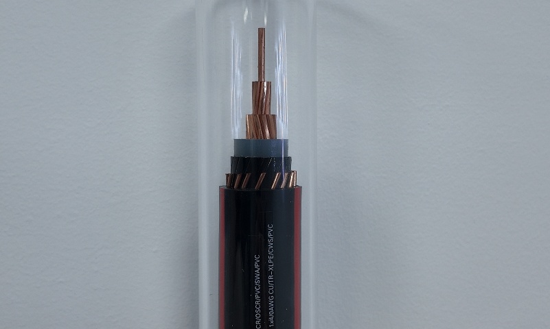
5-46kV TR-XLPE URD Medium Voltage Utility Cables
5–46kV TR-XLPE URD Medium Voltage Utility Power Cables are specifically designed for underground residential distribution and utility power networks. Manufactured with high-quality copper or aluminum conductors and tree-retardant cross-linked polyethylene (TR-XLPE) insulation, these cables provide superior resistance to electrical treeing, moisture ingress, and long-term aging. The TR-XLPE insulation system significantly extends service life in underground installations where environmental stress and moisture exposure are common. Rated for voltage levels from 5kV to 46kV, the cable ensures stable and efficient power transmission under continuous operating conditions. Its robust construction supports direct burial or duct installation, meeting the reliability requirements of modern utility infrastructure. Designed to meet utility and industry performance expectations, TR-XLPE URD cables offer consistent electrical performance, enhanced durability, and reduced maintenance over their operational lifespan.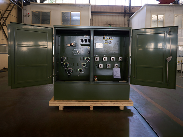
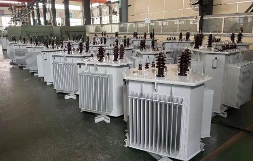
1250kVA Three Phase Pad Mounted Transformer
NPC ELECTRIC's 1250kVA Three Phase Pad Mounted Transformer is a high-performance, oil-immersed distribution transformer engineered for reliable underground power distribution in demanding environments. It delivers exceptional efficiency (up to 99.2% or higher), low no-load and load losses, and a 65°C average winding rise for extended service life exceeding 30-40 years. Key components include high-grade silicon steel core, aluminum or copper windings, 5-position tap changer (±2x2.5%), pressure relief valve, oil level gauge, and tamper-resistant enclosure in Munsell green finish.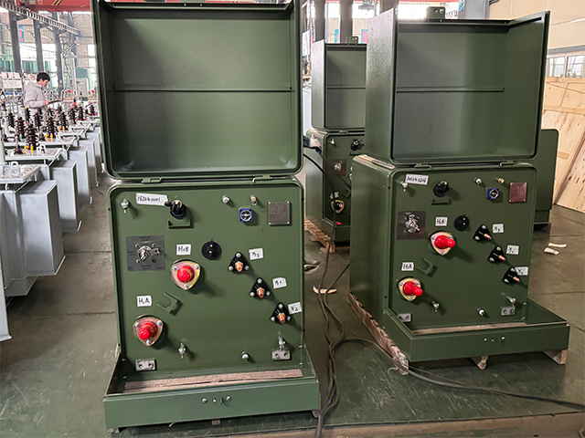
630kVA Single Phase Pad Mounted Transformer
Elevate your underground power distribution with the robust 630kVA Single Phase Pad Mounted Transformer, specifically designed for high-demand residential and commercial loop-feed networks. This oil-immersed, single-phase unit incorporates premium electrical steel laminations and heavy-duty windings to minimize energy losses and provide outstanding thermal performance under continuous loads. Meeting ANSI C57.12.38 and IEEE C57.12.90 standards, this 630kVA padmount transformer delivers precise voltage transformation from primary levels up to 34.5kV to common secondary voltages like 120/240V or 277/480V, supporting extended overloads and long-term reliability in densely populated areas.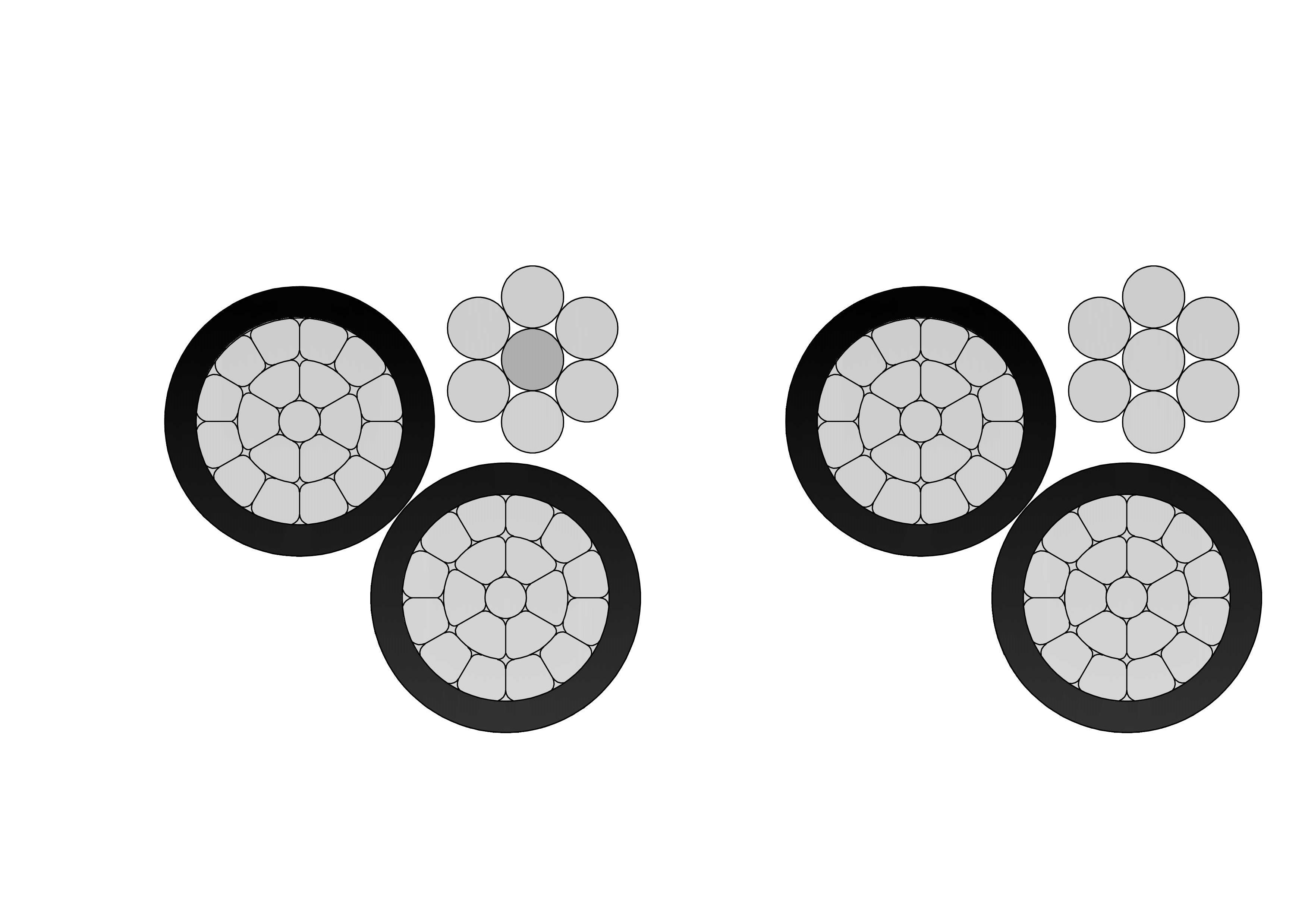
Triplex Service Drop Cable
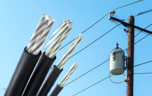
The Triplex Service Drop Cable is designed for overhead power distribution from utility lines to residential and commercial service entrances. It typically consists of two insulated phase conductors and one bare or insulated neutral messenger conductor, twisted together to provide mechanical support and electrical reliability. The phase conductors are insulated with weather-resistant materials such as XLPE or PE, offering excellent resistance to UV radiation, moisture, and environmental aging. Engineered for dependable performance, the Triplex Service Drop Cable ensures stable power delivery while minimizing line losses and installation complexity. Its lightweight yet robust construction allows for easy stringing across poles and buildings, while maintaining adequate tensile strength for long-span applications. Manufactured in accordance with applicable utility and industry standards, this cable is widely used in low-voltage overhead distribution networks where safety, durability, and long service life are essential.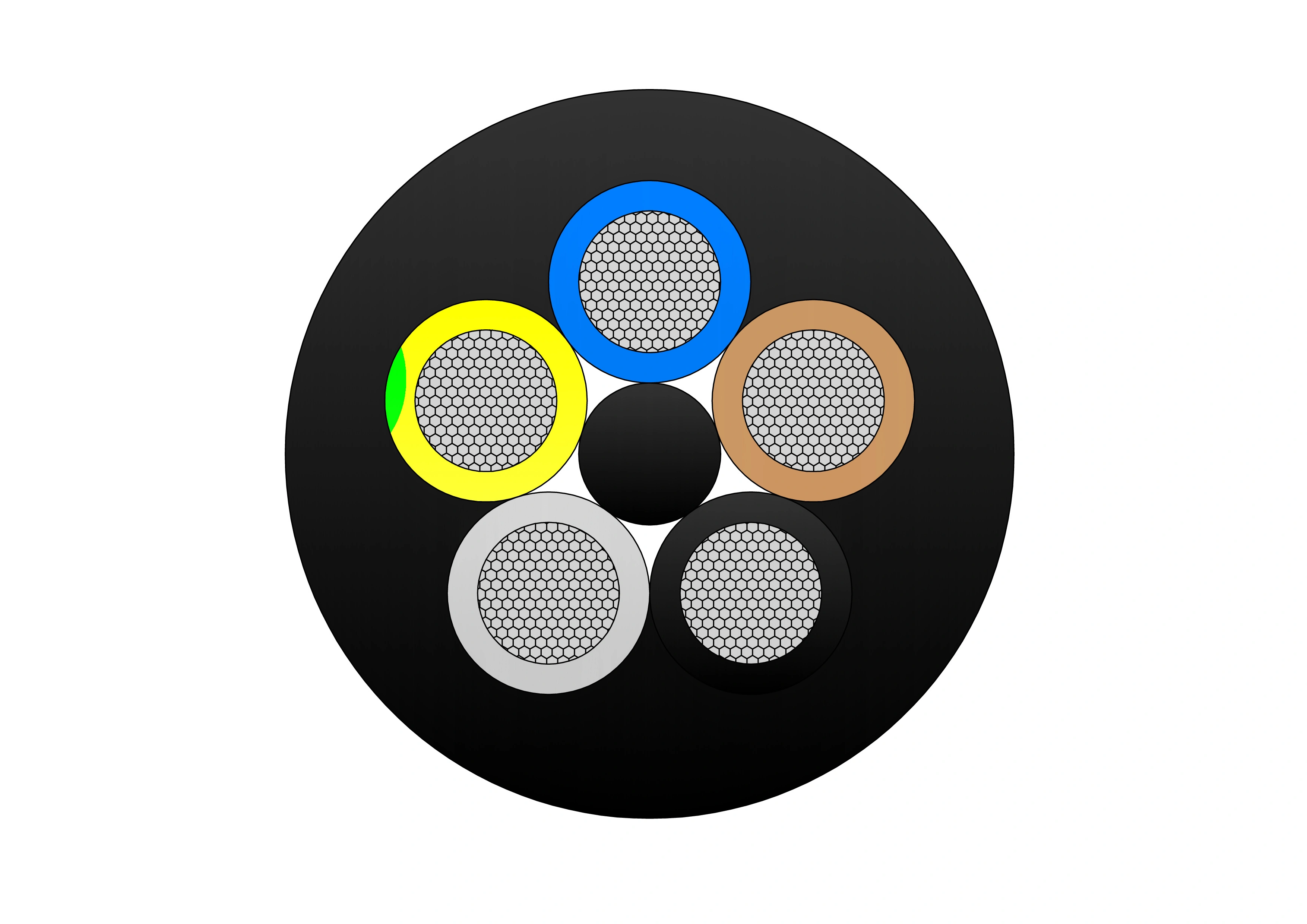
NTSCGECECWOU 3.6/6kV and 6/10kV Cable
The NTSCGECECWOU 3.6/6kV and 6/10kV cable is a flexible medium voltage power cable manufactured to VDE 0250 Part 813 standards, designed for reeling and trailing applications in mining, tunneling, and other demanding industrial environments. Constructed with Class 5 tinned copper conductors, EPR insulation, and a robust halogen-free sheath, it delivers exceptional mechanical strength, flame retardancy, oil resistance, and flexibility. Its copper wire screen ensures EMC protection, while the rugged sheath withstands extreme temperatures, making it suitable for both indoor and outdoor installations in harsh conditions.
500kVA Dry Type Transformer
NPC ELECTRIC 500kVA Dry-Type Transformer offers reliable and efficient power distribution with a compact, oil-free design. It ensures safe, low-maintenance operation with advanced insulation and cooling systems, making it ideal for industrial and commercial use. With a capacity of 500kVA, it delivers stable performance while being environmentally friendly and cost-effective. Key characteristics feature three-phase design (single-phase adaptable), primary voltages 208V–600V (e.g., 480V Delta, 600V Delta), secondary voltages such as 208Y/120V, 480Y/277V, or custom, aluminum or copper windings, 150°C rise (standard) or 115°C/80°C with 220°C insulation class, ±2×2.5% primary taps, NEMA 1 ventilated enclosure (NEMA 3R/encapsulated options), natural convection cooling (AN), electrostatic shielding, and low sound levels per NEMA.
7500kVA Dry Type Transformer
7500kVA Dry Type Transformer is a high-capacity, reliable power solution designed for large-scale industrial and commercial applications. With a robust 7500kVA rating, it incorporates advanced dry-type insulation technology, ensuring enhanced safety, minimal maintenance, and exceptional durability. Engineered for demanding environments, this transformer delivers stable, efficient, and low-noise operation while reducing environmental impact. The NPC ELECTRIC 7500kVA Dry Type Transformer is the ideal choice for high-power applications, providing secure and continuous power distribution for critical infrastructure. Typical attributes encompass three-phase construction, primary voltages 208V–600V (e.g., 480V Delta, 600V Delta), secondary voltages such as 208Y/120V, 480Y/277V, or custom, aluminum or copper windings, 150°C rise (standard) or 115°C/80°C with 220°C insulation class, ±2×2.5% primary taps, NEMA 1 ventilated enclosure (NEMA 3R/encapsulated options), natural convection cooling (AN), electrostatic shielding, and low sound levels per NEMA.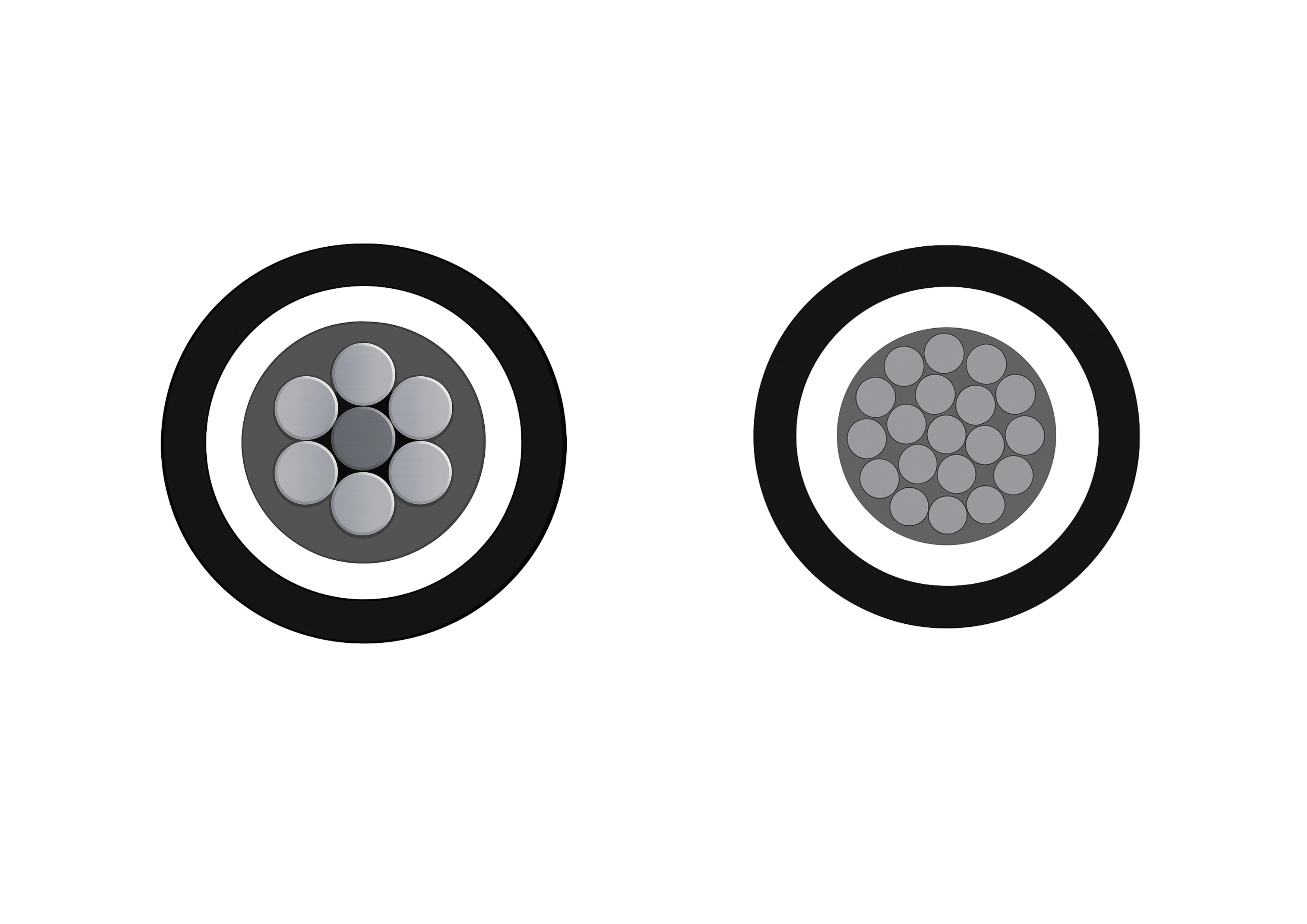
25kV 3-Layer AAAC/ACSR/AAC Tree Wire - Triple Layer Covered MV Conductor
The 3-Layer 25kV AAAC/ACSR/AAC Tree Wire is a specialized covered medium-voltage overhead conductor developed for distribution lines in areas with dense vegetation. It uses concentrically stranded AAAC, ACSR, or AAC conductors protected by a triple-layer system of track-resistant HDPE or XLPE. The multi-layer covering delivers exceptional tracking resistance, abrasion protection, and weatherability while greatly reducing the risk of electrical faults from tree limb contact and helping minimize wildfire ignition potential. This advanced design allows closer spacing to vegetation and lowers vegetation management costs. Suitable for conventional overhead or spacer cable systems, the 3-Layer 25kV AAAC/ACSR/AAC Tree Wire offers a cost-effective solution for improving line reliability. It complies with ICEA and ASTM standards and undergoes extensive quality testing to ensure long-term performance and safety.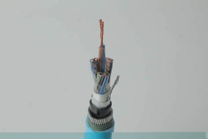
Instrumentation Cables—PVC Insulated, Overall Screened, Unarmoured PVC Sheathed Cables (CU/PVC/OSCR/PVC)
Instrumentation Cables CU/PVC/OSCR/PVC are PVC Insulated, Overall Screened, Unarmoured PVC Sheathed Cables. They are multi-conductor cables that carry and transport low-voltage electrical signals. These low-voltage signals are used to control and monitor electrical power systems. Instrumentation cables have many different industrial applications that include broadcasting, equipment control, such as drilling and pumping in the oil and gas industry, and data transfer, which includes analog and digital signals. They are manufactured according to the BS EN 50288-7 and BS EN 50288-1 standards to ensure quality. Depending on the application, instrumentation cables can be insulated with PVC or XLPE; the cables can be armoured or unarmoured. The sheathing materials can be of PVC, LSZH, or PE. The cables can have additional flame retardant or flame retardant properties, and they can be manufactured with special protections such as lead sheaths, or DRYLAM or AIRBAG technology.
1/0 Neritina Aluminum Conductor Triplex Overhead Service Drop Cable
1/0 Neritina Aluminum Conductor Triplex Overhead Service Drop Cable is designed for reliable secondary overhead power distribution from utility poles to residential and light commercial service entrances. The triplex structure consists of two insulated aluminum phase conductors helically wrapped around a bare aluminum neutral messenger, which provides both electrical grounding and mechanical support. The 1/0 Neritina conductor size offers enhanced current-carrying capacity, strong tensile performance, and controlled sag characteristics, making it suitable for longer spans and higher service loads. Aluminum conductors reduce overall cable weight while delivering excellent corrosion resistance and ease of installation in outdoor environments. Manufactured in compliance with ASTM and utility specifications, the 1/0 Neritina Aluminum Conductor Triplex Overhead Service Drop Cable ensures stable electrical performance, long service life, and dependable mechanical integrity. It is widely adopted by utilities and contractors seeking a cost-efficient and durable overhead service drop solution.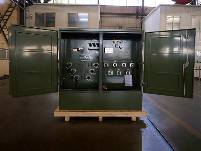
300kVA Three Phase Pad Mounted Transformer
The 300kVA three-phase pad transformer is an efficient and reliable power device designed for commercial, industrial and distribution systems. The transformer provides a high power capacity of 300kVA, which can provide a stable three-phase power supply for high-load equipment, ensuring efficient and smooth operation of the power system. Its sturdy housing adopts a protective design that meets the NEMA 3R standard, which can effectively resist the invasion of the external environment and is suitable for outdoor installation.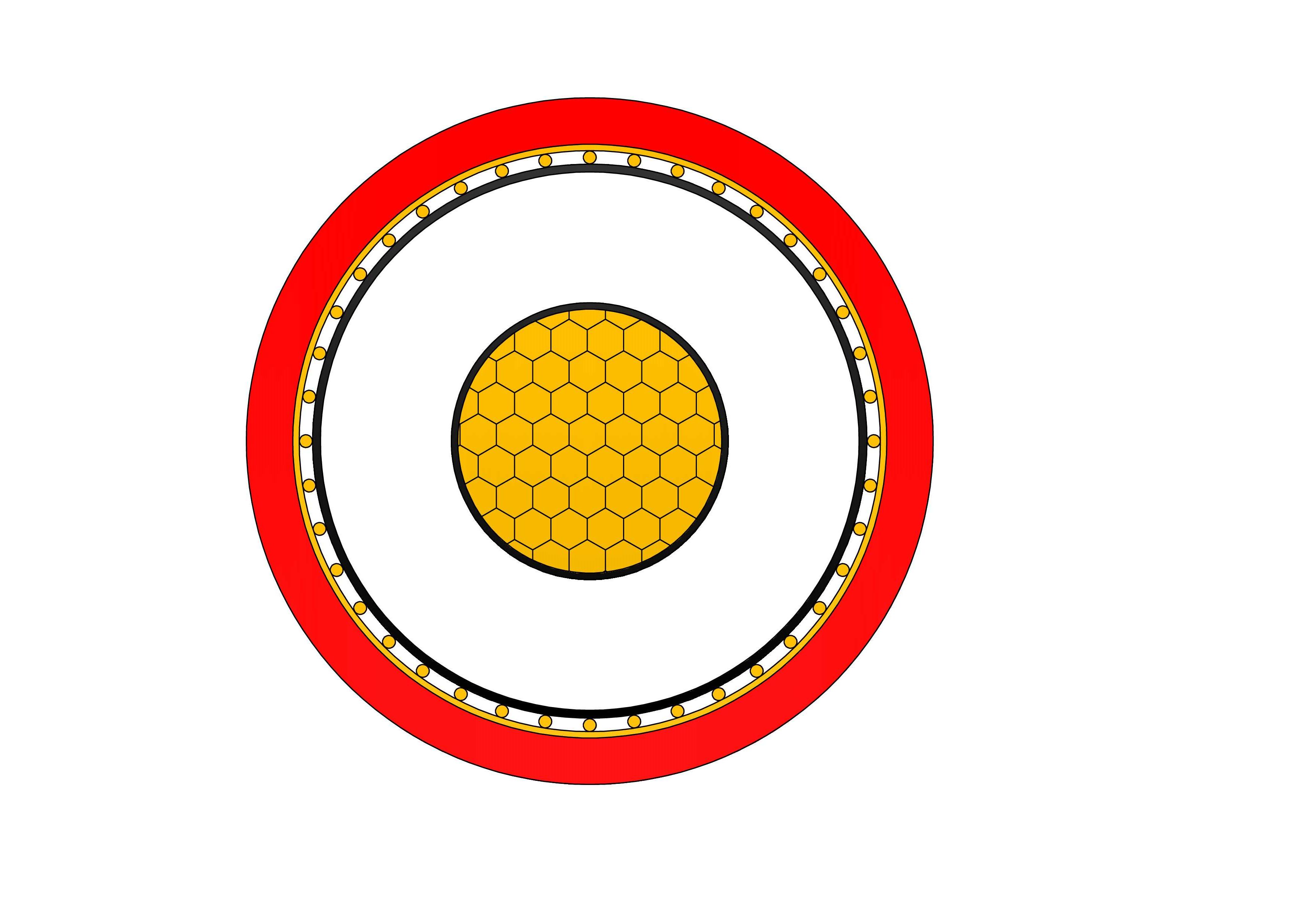
N2XSY Medium Voltage Power Cable(6/10kV, 12/20kV, 18/30kV)
N2XSY are medium voltage power cables with copper conductors and cross-linked polyethylene (XLPE) insulation, designed according to DIN VDE 0276-620 standards. Constructed with high-purity copper conductors, thermosetting XLPE insulation, metallic screen (copper tape or wires), and tough PVC outer sheath, it meets IEC 60502-2 requirements. The screen ensures electromagnetic compatibility and fault protection. Low tan delta, high breakdown strength, and excellent thermal endurance minimize losses and support overloads. PVC sheath provides solid mechanical and moisture protection for fixed installations. Optional longitudinal water-blocking improves performance in damp areas. Flame-retardant and easy to handle, the N2XSY Medium Voltage Power Cable is favored for power grids, manufacturing plants, commercial developments, and renewable energy sites demanding robust single-core medium voltage cabling with proven durability and cost efficiency in buried or tray installations worldwide.
(N)TSCGEWOU 3.6/6kV, 6/10kV, 8.7/15kV and 12/20kV ATB Cable
The (N)TSCGEWOU 3.6/6kV, 6/10kV, 8.7/15kV, and 12/20kV ATB Cable is a medium voltage flexible power cable designed in compliance with VDE 0250 standards. It features Class 5 tinned copper conductors, EPR rubber insulation, semi-conductive layers, halogen-free flame-retardant rubber sheath, and an earth detection conductor. The ATB construction ensures superior mechanical strength, oil resistance, abrasion resistance, and flame retardancy, making it ideal for open-pit mining, tunneling, and other heavy-duty mobile equipment applications under extreme mechanical stress. It includes tinned class 5 copper phase conductors, semi-conductive screens, EPR insulation for reliable dielectric and thermal performance (90°C rating), copper braid screen, control conductors, monitoring conductor (ÜL), anti-torsion braid to reduce twisting under load, and a robust rubber sheath resistant to oils, flames, abrasion, and mechanical damage.Welcome your inquiry
Honesty, Integrity, Frugality, Activeness and Passion