How to Choose Power Transformers for Utility-Scale Solar & Renewable Energy Projects
2026-06-29
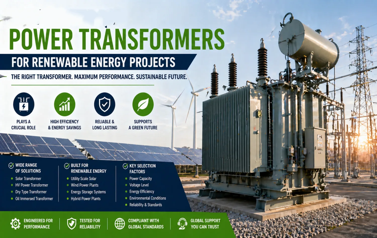
Why Power Transformers Play a Crucial Role in Modern Renewable Energy Projects
Power transformers serve as the backbone of grid integration for renewable generation. In utility-scale solar farms and large-scale renewable energy power plants, they step up voltages from solar inverters or wind turbines to transmission levels while maintaining stability and minimizing losses. Choosing the right renewable energy transformer directly impacts project reliability, energy efficiency, and long-term profitability.
From real-world engineering experience on international export projects, improper selection leads to higher losses, accelerated aging due to thermal cycling, harmonic issues from inverters, and costly delays. This practical guide walks through a systematic, science-based approach, incorporating 2026 market realities.
Types of Power Transformers Suitable for Renewable Energy Applications
1.1 Oil Immersed Power Transformer vs Dry Type Solar Energy Power Capacity Units
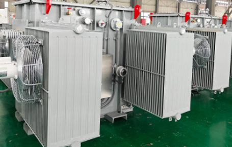
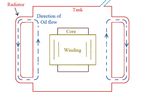
Oil-immersed power transformers remain the preferred choice for most utility-scale solar installations thanks to excellent thermal management and higher overload capability. They handle the variable loading patterns of solar generation effectively through ONAN/ONAF cooling, delivering efficiencies often exceeding 99% at rated capacity.
Dry-type solar energy power capacity transformers, typically cast-resin, offer superior fire safety and lower maintenance, making them ideal for urban or environmentally sensitive sites. However, they often require derating in high-ambient conditions common to desert solar farms. Field data consistently shows that oil-immersed designs provide better overall lifecycle performance in MW-scale applications.
The table below provides a clear technical comparison based on practical field performance in renewable projects:
Table 1: Oil-Immersed vs Dry-Type Transformers for Utility-Scale Solar Applications
|
Parameter |
Oil-Immersed Power Transformer |
Dry-Type Solar Transformer |
|
Typical Capacity Range |
2.5 MVA – 350+ MVA |
Up to 10 MVA (practical limit for renewables) |
|
Voltage Range |
Up to 400 kV+ |
Typically up to 35 kV |
|
Efficiency at Full Load |
98.8% – 99.7% |
96.5% – 98.5% |
|
Cooling Method |
ONAN / ONAF / ONAF |
AN / AF |
|
Fire Safety |
Moderate (requires oil containment) |
Excellent (cast-resin, flame-retardant) |
|
Overload Capability |
High (excellent thermal inertia) |
Moderate (requires derating in high ambient) |
|
Maintenance |
Higher (oil monitoring & filtration) |
Lower (no oil) |
|
Best Application |
Outdoor collector substations, high voltage scale solar farms |
Indoor inverter skids, urban or fire-sensitive sites |
|
Lifecycle Cost (TOC) |
Generally lower for MW-scale projects |
Higher upfront, better in constrained environments |
Source: Compiled from typical IEC 60076-based specifications and field data in utility-scale solar deployments.
This comparison shows why oil-immersed power transformer designs are favored for the majority of large-scale renewable energy power plants, while dry-type units serve niche requirements.
1.2 Generator Step-Up (GSU) and Inverter Transformers for Solar and Wind
Inverter transformers must withstand the harmonic distortion generated by modern solar inverters. Specialized renewable energy transformer designs incorporate reinforced insulation and K-factor ratings to reduce eddy current losses. Generator step-up transformers in hybrid plants require additional robustness against bidirectional power flows and frequent start-stop cycles.
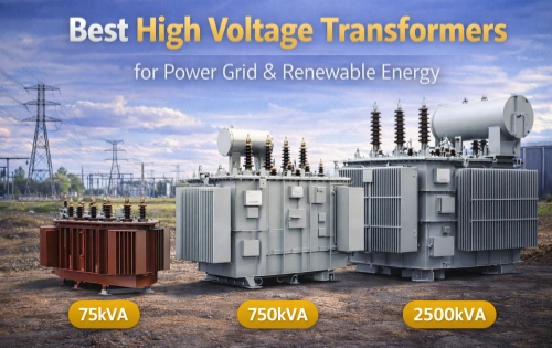
Determining Optimal Power Capacity and Voltage Ratings
Transformer sizing starts with a detailed load flow analysis. For utility-scale solar, aggregate inverter AC output and apply a conservative 8–15% margin to accommodate peak irradiance, future expansion, and overload conditions without excessive capital cost.
Voltage selection must align precisely with both inverter LV output (typically 0.69 kV or 1.1 kV) and the grid interconnection voltage (33 kV up to 400 kV+). HV power transformer impedance values are critical—they must limit fault currents while ensuring tight voltage regulation (±0.5% no-load typical per IEC 60076).
On-load tap changers (OLTC) with wide ranges enhance operational flexibility under fluctuating renewable output and evolving grid codes. Practical projects always validate specifications through detailed interconnection studies.
Table 2: Typical Voltage Ratings and Impedance for Renewable Energy Transformers
|
Transformer Type |
LV Side (Inverter / Generator) |
HV Side (Grid) |
Typical Impedance (%) |
Common Power Rating (MVA) |
Key Application |
|
Inverter Step-Up Transformer |
0.69 kV / 1.1 kV |
33 kV / 34.5 kV |
6 – 8% |
2 – 8 |
Direct connection to solar inverters |
|
Collector / Step-Up Transformer |
33 kV / 34.5 kV |
132 kV / 220 kV |
8 – 12% |
20 – 100 |
Utility-scale solar collector substation |
|
GSU / Main Power Transformer |
13.8 – 34.5 kV |
230 kV / 345 kV |
8 – 15% (avg. 9–10%) |
50 – 350 |
Large-scale renewable energy power plants interconnection |
|
HV Power Transformer |
132 kV |
400 kV+ |
10 – 18% |
100 – 500+ |
Transmission tie-in |
On-load tap changers (OLTC) with ±10% to ±20% range are recommended to maintain voltage regulation under variable renewable output.
Managing Harmonics, Thermal Cycling, and Solar Inverter Compatibility
Solar inverters produce significant harmonic content, primarily 5th, 7th, and 11th orders. Renewable energy transformers need K-4 to K-20 ratings, depending on inverter technology and system configuration. Advanced designs use finite element analysis to optimize winding geometry and minimize hot spots.
Thermal cycling from daily solar ramp-up and ramp-down accelerates insulation aging. Dual temperature rise ratings (55/65°C) and high-quality grain-oriented or amorphous core materials help mitigate this stress. Delta-wye configurations with properly grounded neutrals improve zero-sequence handling and support IEEE 1547-compliant ride-through capabilities.
Achieving High-Efficiency Power Systems and Loss Optimization
Energy efficiency has become a decisive factor in 2026. Compliance with IEC 60076-20, updated DOE standards, and regional Ecodesign requirements drives the adoption of low-loss cores and advanced cooling. Even small efficiency gains (0.3–0.7%) translate into substantial LCOE reductions over a 30-year project life.
Amorphous core transformers excel in minimizing no-load losses, while natural ester (vegetable) oils enhance fire safety and environmental performance compared to traditional mineral oil. Total ownership cost (TOC) analysis, factoring capitalized losses at site-specific energy values, consistently favors premium high-efficiency power systems over lowest-first-cost options.
Table 3: Typical Loss Comparison – Conventional vs High-Efficiency Designs (per 1000 kVA base, approximate values at 50/60 Hz)
|
Core / Design Type |
No-Load Loss (Core Loss) |
Load Loss (at Rated Current) |
Total Loss at 100% Load |
Efficiency Gain |
Best For Renewable Projects |
|
Conventional CRGO Silicon Steel |
1,100 – 1,400 W |
10,000 – 12,000 W |
~11,500 W |
Baseline |
Standard applications |
|
Amorphous Core Transformer |
300 – 550 W |
9,500 – 11,500 W |
~10,200 W |
0.4 – 0.8% |
High-voltage scale solar farms with high no-load hours |
|
High-Efficiency Oil-Immersed (Ester Oil + Optimized Design) |
600 – 900 W |
9,000 – 10,500 W |
~9,800 W |
0.3 – 0.6% |
Utility-scale solar with stringent LCOE targets |
|
1,200 – 1,800 W |
11,000 – 14,000 W |
~13,000 W |
Lower |
Fire-sensitive or indoor locations |
Amorphous core transformers significantly reduce no-load losses (often by 60–70%), making them ideal for solar applications where transformers may operate at partial load during non-peak sunlight hours. Natural ester oils further improve fire safety and biodegradability.
Site-Specific Environmental and Safety Design Considerations
Environmental conditions heavily influence transformer specification. High-ambient desert projects may require forced cooling or oversized radiators. Coastal installations demand enhanced corrosion protection and creepage distances. Seismic zones require reinforced tank designs and anchoring systems.
Safety features such as sudden pressure relays, Buchholz protection, fiber-optic winding temperature monitoring, and oil spill containment are standard on quality oil-immersed power transformer units. Acoustic performance must also meet local permitting limits through core clamping and enclosure treatments.
Standards Compliance and Grid Code Requirements
Successful international projects demand full compliance with IEC 60076 series for performance and testing, IEEE C57 for application guidance, and IEEE 1547 / IEEE 2800 for inverter-based resource interconnection. Grid codes increasingly require dynamic reactive power support and low-voltage ride-through capabilities indirectly supported by stable transformer voltage regulation.
Factory acceptance testing (FAT), including loss measurement, impulse testing, and power quality validation, forms a critical quality gate before shipment.
Selecting Reliable Power Transformer Manufacturers and Procurement Strategy
Partnering with experienced power transformer manufacturers is essential in a market still facing tight supply for large HV units. Evaluation criteria should include:
- Proven delivery record on utility-scale solar projects
- In-house design capability for renewable-specific stresses (harmonics, cyclic loading)
- Transparent efficiency guarantees backed by type test reports
- Strong after-sales support, including digital monitoring integration (smart transformer features)
- Ability to meet international certifications and export documentation requirements
Early engagement during the FEED stage helps avoid change orders and secures realistic lead times, which can still exceed 18 months for custom high-voltage scale solar farm transformers.
Lifecycle Cost Analysis, Maintenance, and Future-Proofing Your Investment
Comprehensive lifecycle costing integrates CAPEX, installation, capitalized losses, maintenance, and end-of-life considerations. Condition monitoring technologies—dissolved gas analysis (DGA), partial discharge sensors, and IoT-enabled bushing monitoring—enable predictive maintenance and extend service life beyond 30–40 years.
Future-proofing involves specifying extra capacity margins, wide tap ranges, and modular designs that facilitate upgrades as plants evolve toward hybrid renewable + storage configurations. The shift toward smart transformers with integrated sensors supports real-time grid support functions demanded by higher renewable penetration.
Conclusion: Strategic Transformer Selection for Long-Term Renewable Success
Selecting the optimal power transformers for renewable energy projects requires balancing electrical performance, environmental resilience, regulatory compliance, and economic outcomes. By focusing on solar transformer designs engineered for inverter characteristics, ensuring compatibility with high-voltage-scale solar farms, and collaborating with qualified power transformer manufacturers, developers achieve superior energy efficiency, enhanced reliability, and minimized operational risks.
Choosing the right power transformer for renewable energy projects is a critical engineering decision that impacts system performance, reliability, and cost efficiency.
From HV power transformer solutions for transmission to specialized solar transformer designs for PV systems, each transformer type serves a unique purpose. By focusing on power capacity, energy efficiency, and environmental conditions, project developers can ensure optimal performance in modern renewable energy systems.
For global EPC contractors and investors, partnering with experienced power transformer manufacturers is key to delivering successful, scalable, and sustainable energy projects.
Related Articles
Related Products
3750kVA Three Phase Pad Mounted Transformer
NPC ELECTRIC's 3750kVA Three Phase Pad Mounted Transformer is a heavy-duty, oil-immersed compartmental-type distribution transformer engineered for high-capacity underground power distribution in large-scale utility and industrial settings. This high-power pad-mounted transformer reduces energy consumption, lowers total ownership costs through superior efficiency and longevity (30+ years), and supports demanding loads with features like vacuum fault interrupters and harmonic mitigation, ideal for reliable, secure power in expansive commercial-industrial networks.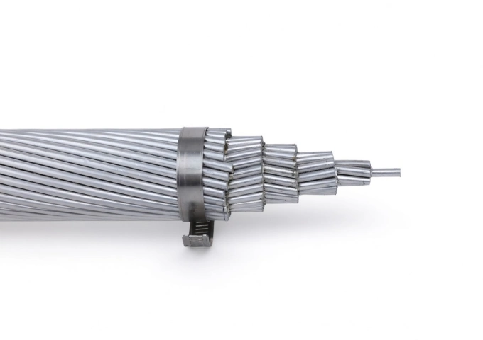
1113 MCM Marigold AAC Cable
The 1113 MCM Marigold AAC Cable is a high-performance All Aluminum Conductor designed for demanding overhead power transmission and distribution lines. Manufactured with 37 strands of premium 1350-H19 aluminum wire in a concentric lay configuration, this bare conductor provides excellent electrical conductivity with a low DC resistance of 0.0155 ohms per 1000 ft at 20°C. Featuring an overall diameter of 1.216 inches and a rated breaking strength of 19,300 lbs, the Marigold AAC delivers a robust ampacity of 1083 amps while weighing only 1045.4 lbs per 1000 ft. Its optimized strength-to-weight ratio minimizes sag and structural loading. Fully compliant with ASTM B-230 and B-231 standards, the 1113 MCM Marigold AAC Cable offers outstanding corrosion resistance for long-term durability in harsh outdoor environments, making it the preferred choice for utility networks requiring cost-effective, high-reliability bare aluminum conductors.2Y-high-voltage-power-cable-2.webp)
A2XS(FL)2Y MDPE High Voltage 26/45 (52)kV Power Cable
The A2XS(FL)2Y MDPE High Voltage Power Cable is a single-core aluminum conductor cable with XLPE insulation and an MDPE sheath, rated 26/45 (52) kV. Designed for reliable medium-voltage power transmission, it meets IEC 60840 standards, providing excellent electrical performance, mechanical protection, and environmental resistance. Its construction includes an aluminum conductor, semi-conductive conductor screen, XLPE insulation, semi-conductive insulation screen, semi-conductive water swelling tape, copper wire metallic screen, longitudinal aluminum tape with PE copolymer coating, and an MDPE sheath. Water-blocking tape prevents water propagation inside the cable, ensuring dependable operation in power stations, industrial plants, and distribution networks. Suitable for underground, underwater, indoor, outdoor, and duct installations, this cable is ideal for distribution networks, generation unit connections, and industrial processes.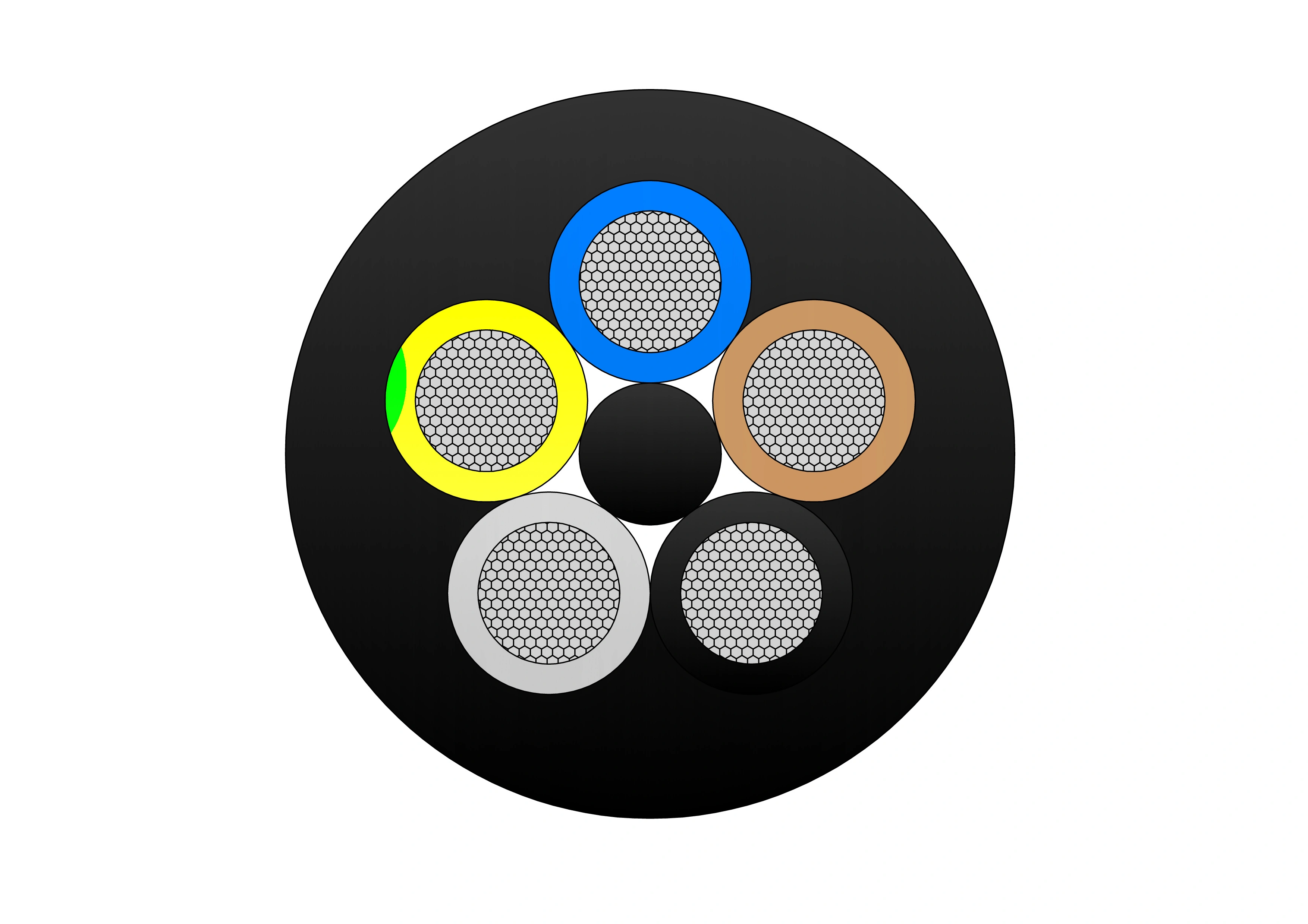
Type 409 Flexible Copper Screened Mining Cable With Central Pilot
The Type 409 Flexible Copper Screened Mining Cable with Central Pilot is a heavy-duty flexible cable engineered for reliable and safe underground mining operations. It features finely stranded tinned copper conductors (class 5) for excellent flexibility and corrosion resistance, EPR (ethylene propylene rubber) insulation for superior dielectric strength and 90°C continuous thermal rating, an overall tinned copper braid screen providing effective EMI protection and grounding, a central pilot core for earth continuity monitoring, safety interlocks, and fault detection, and an extra-heavy-duty flame-retardant rubber outer sheath resistant to oil, abrasion, tearing, crushing, impact, and chemicals. Compliant with AS/NZS 2802 and mining safety standards, it supports high tensile loads, frequent reeling/drag, tight bending radii, and reliable performance in wet, dusty, and hazardous mine conditions. The Type 409 is ideal for power supply to continuous miners, shuttle cars, longwall equipment, drills, and other mobile machinery in coal and metalliferous mines, ensuring enhanced safety through pilot core monitoring and maximum durability.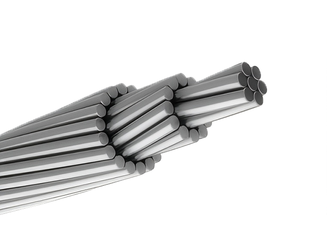
556.5 MCM OSPREY ACSR Conductor Cable
The ACSR CAA 556.5 MCM 18/1F OSPREY conductor is a durable and efficient Aluminium Conductor Steel Reinforced (ACSR) cable, engineered to deliver consistent performance in overhead power transmission and distribution systems. With its construction of 18 hard-drawn 1350-H19 aluminium strands wrapped around a single galvanized steel wire, this conductor offers a dependable combination of lightweight conductivity and mechanical strength. Complying with ASTM B232 standards, the OSPREY conductor is ideal for medium- to long-span installations, particularly where increased mechanical support is necessary. The steel core, available with Class A or B galvanization, enhances corrosion resistance while supporting the conductor’s tensile integrity under challenging environmental and load conditions. Its 18/1F construction makes it particularly suited for projects where a balance of performance, durability, and cost-effectiveness is essential. It is widely used by utilities in transmission infrastructure, especially where moderate-to-high current capacity is required without compromising on mechanical reliability.
6 Pekingese Aluminum Conductor Duplex Overhead Service Drop Cable
The 6 Pekingese Aluminum Conductor Duplex Overhead Service Drop Cable is designed for safe and efficient secondary overhead power distribution from utility lines to residential and light commercial service entrances. The duplex configuration consists of two concentrically stranded aluminum conductors, typically serving as a phase conductor and a neutral messenger, providing reliable electrical transmission and mechanical support. The No. 6 Pekingese conductor size is well suited for short-span service drop installations, offering stable current-carrying capacity with controlled sag and adequate tensile strength. Aluminum construction ensures lightweight handling, excellent corrosion resistance, and simplified installation in outdoor environments. Manufactured in accordance with ASTM standards and utility specifications, the 6 Pekingese Aluminum Conductor Duplex Overhead Service Drop Cable delivers uniform stranding, consistent conductivity, and dependable long-term performance. It is widely selected by utilities and contractors seeking a cost-effective, durable solution for overhead service drop applications.
(N)TSCGEWOU 3.6/6kV, 6/10kV, 8.7/15kV and 12/20kV Submersible Cable
The (N)TSCGEWOU 3.6/6kV, 6/10kV, 8.7/15kV and 12/20kV Submersible Cable is a robust, flexible medium-voltage cable optimized for full submersion in mining and industrial water environments. It comprises class 5 tinned copper conductors for corrosion resistance, semi-conductive screens, EPR insulation for reliable dielectric and thermal properties (90°C rating), copper braid screen for shielding, control/monitoring conductors, and a high-performance watertight rubber outer sheath incorporating water-blocking elements to resist high hydrostatic pressure and prevent longitudinal/transverse water ingress. Compliant with DIN VDE 0250 and IEC standards, it provides excellent mechanical strength, flame retardancy, oil/chemical resistance, and flexibility for dynamic submersible use. The (N)TSCGEWOU Submersible is ideal for reliable power delivery to submersible pumps, dredgers, and underwater equipment in flooded mines, tunnels, and offshore applications.
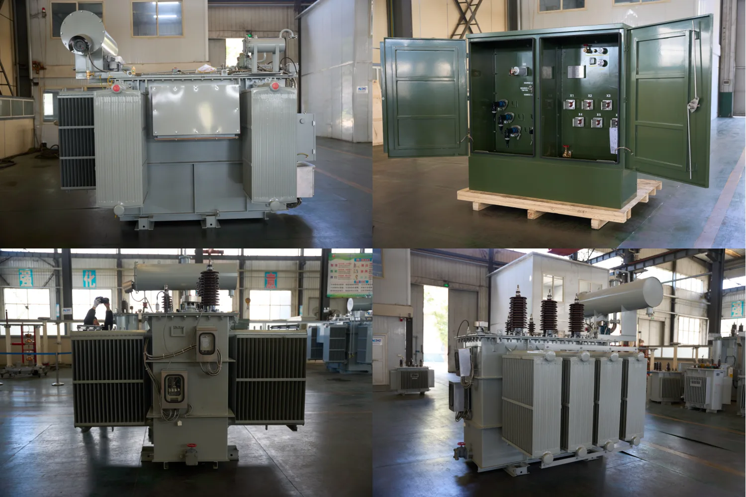
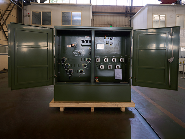
4000kVA Oil Immersed Transformer
4000kVA Oil Immersed Transformer is designed for medium and large-scale power distribution systems that require high reliability, strong overload capacity, and long-term stable operation. The transformer adopts a fully sealed oil-immersed structure, effectively preventing moisture ingress and oil oxidation, thereby extending service life and reducing maintenance frequency. The transformer features excellent thermal performance and robust insulation strength, ensuring stable operation under continuous load or fluctuating grid conditions. Advanced oil circulation and cooling structure enhance heat dissipation, while precise manufacturing processes guarantee low noise and high mechanical strength.
200kV High Voltage Power Transformers – Reliable & Efficient Solutions
The 200kV High Voltage Power Transformer is engineered to support large-scale power transmission systems requiring high reliability, electrical efficiency, and long-term operational stability. Designed for modern grid infrastructures, this transformer enables safe and efficient voltage transformation across extended transmission distances while minimizing energy losses. Its oil-immersed insulation system ensures strong dielectric performance and effective thermal management under continuous high-voltage stress. The transformer structure is optimized to withstand electrical, thermal, and mechanical loads, supporting stable operation under fluctuating demand conditions. Precision manufacturing and advanced design techniques contribute to low maintenance requirements and extended service life. Suitable for utility substations and critical power nodes, this transformer delivers dependable performance for high-capacity transmission and grid interconnection projects.
(N)TSCGEWOU 3.6/6kV, 6/10kV, 8.7/15kV and 12/20kV ATB Cable
The (N)TSCGEWOU 3.6/6kV, 6/10kV, 8.7/15kV, and 12/20kV ATB Cable is a medium voltage flexible power cable designed in compliance with VDE 0250 standards. It features Class 5 tinned copper conductors, EPR rubber insulation, semi-conductive layers, halogen-free flame-retardant rubber sheath, and an earth detection conductor. The ATB construction ensures superior mechanical strength, oil resistance, abrasion resistance, and flame retardancy, making it ideal for open-pit mining, tunneling, and other heavy-duty mobile equipment applications under extreme mechanical stress. It includes tinned class 5 copper phase conductors, semi-conductive screens, EPR insulation for reliable dielectric and thermal performance (90°C rating), copper braid screen, control conductors, monitoring conductor (ÜL), anti-torsion braid to reduce twisting under load, and a robust rubber sheath resistant to oils, flames, abrasion, and mechanical damage.
Duplex URD Cable
The Duplex URD Cable is a high-performance 600V underground residential distribution cable designed for reliable service entrance and secondary power delivery. It consists of two insulated AA8000 aluminum alloy phase conductors and a concentric neutral, all protected by a tough black polyethylene sheath. The duplex configuration provides a compact, easy-to-install solution for direct burial applications. Manufactured with XLPE insulation, this cable offers excellent electrical properties, moisture resistance, and long-term durability. The Duplex URD Cable is lightweight, flexible, and cost-effective compared to copper alternatives while maintaining high conductivity and mechanical strength. It meets UL 854, ICEA, and ASTM standards and undergoes rigorous quality testing from raw materials to finished product, ensuring consistent performance in underground environments.
RZ1-K XLPE LSZH Flexible Cable
RZ1-K XLPE LSZH Flexible Cable is for installation where fire,smoke emission and toxic fumes create a potential threat to life and equipment. A flexible power and control cable designed for fixed applications.Manufactured with flexible conductors with halgon free cables. Excellent flexibility allows tight bending radii, simplifying installation in complex routing. Resistant to oils, chemicals, and moisture, the RZ1-K XLPE LSZH Flexible Cable offers superior thermal performance and long service life.
120kV High-Voltage Three-Phase Oil-Immersed Power Transformer
The 120kV High-Voltage Three-Phase Oil-Immersed Power Transformer is engineered for reliable and efficient operation in transmission networks and high-voltage substations. Designed with high-permeability silicon steel cores and precision-wound copper conductors, it delivers low losses, excellent thermal performance, and strong short-circuit withstand capability. The oil-immersed cooling system ensures effective heat dissipation, supporting continuous operation under heavy-load and fluctuating grid conditions. A robust tank structure, advanced insulation system, and outdoor-rated protection allow stable operation in harsh climates and demanding environments. Manufactured in accordance with IEC, IEEE, and ANSI standards, this transformer is widely applied in utility grids, industrial power systems, and large-scale infrastructure projects where high reliability, long service life, and stable voltage transformation are essential.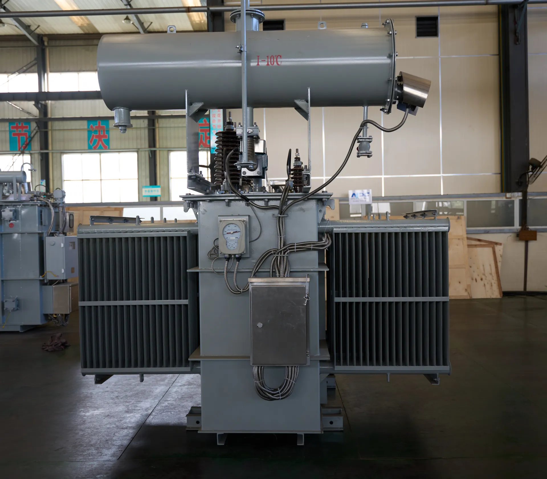
45kV 2500kVA Weatherproof & Oven-Proof Oil-Immersed Power Transformer
The 45kV 2500kVA Weatherproof & Oven-Proof Oil-Immersed Power Transformer is engineered for demanding outdoor applications requiring high durability, stable voltage transformation, and long-term operational reliability. Designed with premium cold-rolled silicon steel, high-conductivity copper windings, and a reinforced oil-immersed cooling system, the transformer ensures excellent thermal stability and resistance to overheating. Its oven-proof construction allows the unit to withstand high ambient temperatures, while the weatherproof enclosure provides protection against rain, dust, humidity, and corrosive environments. With advanced insulation, strong short-circuit endurance, and compatibility with both off-load and on-load tap changers, this 45kV outdoor transformer is ideal for substations, industrial facilities, renewable energy sites, and long-distance power distribution systems. Built in accordance with IEC 60076 standards, it delivers efficiency, reliability, and lifespan required for critical grid infrastructure.
AMHERST AAAC Conductor Cable
AMHERST AAAC (All Aluminum Alloy Conductor) cables comply with ASTM B399 standards and offer high strength, good conductivity, and excellent corrosion resistance. With 300 mm² nominal area and 37-strand design, it uses heat-treated aluminum-magnesium-silicon alloy (6201-T81) for enhanced strength (295 MPa min) and conductivity (53% IACS min). Meeting ASTM B398, B399, IEC 61089, and BS EN 50182 standards, this cable handles ampacity up to 700A at 75°C and voltages up to 33kV. The all-alloy construction avoids bimetallic corrosion, providing better resistance in harsh conditions than ACSR. Reduced weight minimizes sag and installation expenses, supporting longer spans. The Amherst AAAC Conductor Cable delivers low electrical losses, high mechanical endurance, and excellent weather tolerance. Flame-retardant variants available. Perfect for urban grids, renewable projects, and coastal setups, it provides cost-effective, low-maintenance power delivery in overhead applications globally, excelling in reliability and lifespan over conventional conductors.Welcome your inquiry
Honesty, Integrity, Frugality, Activeness and Passion