OPGW Cables: What Are They and Why Power Grids Need Them
2026-07-02
1. Introduction to OPGW Cables: Defining the Dual-Purpose Solution
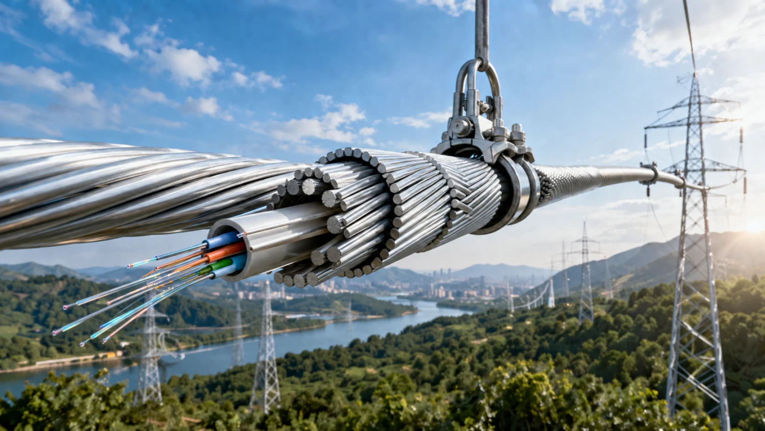
OPGW cable, short for Optical Ground Wire or Optical Fiber Composite Overhead Ground Wire, represents a sophisticated engineering solution that integrates two critical functions into a single overhead cable. At its core, an OPGW cable serves as a traditional ground wire (also known as shield wire or earth wire) while embedding high-capacity optical fibers for data transmission.
From a practical field perspective, transmission line engineers often face the challenge of balancing electrical protection with growing communication demands. Installing separate electric cable systems for grounding and fiber optic links increases costs, structural loads on towers, and maintenance complexity. OPGW resolves this by replacing conventional wires and cables with a hybrid design. The metallic outer layers handle fault currents and lightning strikes, while the inner optical unit provides low-latency, high-bandwidth communication immune to electromagnetic interference.
In modern power grids, where real-time monitoring and automation are non-negotiable, understanding what an OPGW cable is is fundamental. It is not merely an electric cable upgrade but a strategic enabler for grid resilience. Typical deployments occur on high-voltage lines from 110 kV upward, where the cable runs along the top of transmission towers, providing shielding to phase conductors below.
2. Historical Evolution and Technological Maturation
The concept of combining optical fibers with overhead ground wires emerged in the 1980s as utilities sought efficient ways to leverage existing transmission corridors for communication. Early OPGW fiber cable designs addressed limitations of separate installations, such as right-of-way constraints and signal degradation in traditional copper systems.
Over decades, standards like IEEE 1138 have driven rigorous testing for mechanical, electrical, and optical performance. Manufacturers refined constructions to handle extreme short-circuit currents, ice loading, and high winds while maintaining fiber integrity. Today, OPGW cable manufacturer innovations include higher fiber counts (up to 144 or more) and advanced materials like aluminum-clad steel (ACS) and aluminum alloy wires.
From a fieldwork viewpoint, older grids relying on pure metallic ground wires often suffer from communication gaps that delay fault location and response. The evolution to OPGW allows seamless SCADA (Supervisory Control and Data Acquisition) integration and predictive maintenance. This historical shift reflects a broader industry move toward multifunctional infrastructure, reducing capital expenditure over the asset lifecycle. Practical experience shows that well-designed OPGW systems achieve service lives exceeding 30-40 years with proper specification matching to line parameters like span length and fault levels.
3. Technical Structure and Material Composition
A typical OPGW cable features a multi-layered architecture optimized for dual performance. The central optical unit consists of one or more stainless steel or aluminum tubes housing loose-buffer tubes with optical fibers (commonly G.652D single-mode). These tubes are gel-filled for water blocking and fiber protection, allowing excess fiber length to accommodate cable elongation under tension.
Surrounding the core are concentric layers of stranded wires: inner layers often use aluminum-clad steel for high tensile strength and conductivity, while outer layers may incorporate aluminum alloy for optimized electrical performance and corrosion resistance. This design ensures the cable meets or exceeds the short-circuit current capacity and tensile strength of the ground wire it replaces.
Key specifications include:
- Fiber counts: 12 to 144+
- Diameter: Typically 10-30 mm depending on design
- Rated tensile strength (RTS): Up to several hundred kN
- Short-circuit capacity: Often 20-100+ kA²s
- Attenuation: ≤0.21 dB/km at 1550 nm for high-performance fibers
Table 1: Typical OPGW Cable Technical Specifications
|
Parameter |
Typical Value / Range |
Notes / Standards |
|
Fiber Type |
G.652D / G.655 (Single-mode) |
ITU-T compliant |
|
Fiber Count |
12 - 144 fibers |
Up to 288 in advanced designs |
|
Attenuation @ 1550 nm |
≤ 0.21 dB/km |
≤ 0.05 dB per splice |
|
Tensile Strength (RTS) |
50 - 700 kN |
Depends on line span & voltage |
|
Short-Circuit Capacity |
20 - 200+ kA²s (0.5s) |
40°C to 200°C |
|
Cable Diameter |
10 - 30 mm |
Single or multi-layer stranding |
|
Unit Weight |
400 - 1200 kg/km |
Varies with aluminum/steel ratio |
|
Operating Temperature |
-40°C to +80°C |
Installation: -10°C to +50°C |
|
Minimum Bend Radius |
15D (static) / 20D (dynamic) |
D = Cable diameter |
|
DC Resistance (20°C) |
0.08 - 0.98 Ω/km |
Optimized for fault current |
Engineers on-site must verify these parameters against line loading conditions. The metallic components provide low DC resistance for effective grounding, while the optical fibers maintain stable transmission across wide temperature ranges (-40°C to +80°C). This rigorous material science ensures minimal sag under load and superior lightning performance compared to non-conductive alternatives.
4. Key Advantages for Power Grid Reliability and Efficiency
OPGW cables deliver multifaceted benefits that directly impact operational outcomes. Electrically, they excel at dissipating lightning strikes and fault currents, protecting phase conductors and reducing outage frequency. The conductive path bonds towers to ground, enhancing overall system stability.
Optically, OPGW fiber cable enables high-speed, interference-free communication essential for protection relaying, phasor measurement units (PMUs), and wide-area monitoring. In practice, this translates to faster fault isolation—often within milliseconds—minimizing damage and improving SAIDI/SAIFI indices.
Additional advantages include:
- Cost efficiency: Single installation instead of separate ground wire and fiber runs
- Reduced tower loading compared to adding parallel cables
- Future-proof bandwidth for smart grid data, renewable integration, and even leased dark fiber revenue
- Enhanced security: Buried within the metallic structure, fibers are protected from vandalism and environmental degradation
From a maintenance crew's perspective, OPGW simplifies asset management. One cable handles both grounding tests and optical time-domain reflectometer (OTDR) checks. In high-lightning regions, the design's short-circuit rating prevents cascading failures, delivering measurable improvements in grid resilience.
5. Applications in High-Voltage Transmission Lines
OPGW cable finds primary use in overhead transmission lines where dual functionality is paramount. On new 220 kV to 765 kV+ projects, it is installed as the top shield wire, providing both lightning protection and a backbone for utility communication networks.
Practical deployments include interconnecting substations for real-time control, enabling condition monitoring of transformers and breakers, and supporting renewable energy evacuation from remote wind/solar farms. In transmission corridors, opgw cable in transmission line setups facilitates video surveillance, environmental sensors, and integration with emerging technologies like digital twins for grid simulation.
Internationally, utilities deploy it across diverse terrains—from coastal areas requiring corrosion-resistant designs to mountainous regions demanding high tensile strength. For export-oriented manufacturers, customizing OPGW to specific IEC/IEEE standards and local environmental conditions is critical for project success. The cable's ability to carry voice, data, and protection signals makes it indispensable in modern interconnected power grids.
Table 2: Key Performance Requirements for OPGW in Transmission Lines
|
Voltage Level |
Recommended Short-Circuit Capacity (kA²s) |
Typical Fiber Count |
Max Ruling Span (m) |
Primary Applications |
|
110 - 220 kV |
20 - 60 |
24 - 48 |
400 - 600 |
Substation interconnection, SCADA |
|
220 - 500 kV |
60 - 120 |
48 - 96 |
600 - 1000 |
Smart grid monitoring, PMU data |
|
≥ 500 kV (UHV) |
120 - 200+ |
72 - 144+ |
800 - 1200 |
Renewable integration, Wide-area control |
|
Key Consideration |
Fault current & lightning density |
Bandwidth needs |
Terrain & loading |
Grid modernization & digitalization |
6. Practical Installation and Maintenance Considerations
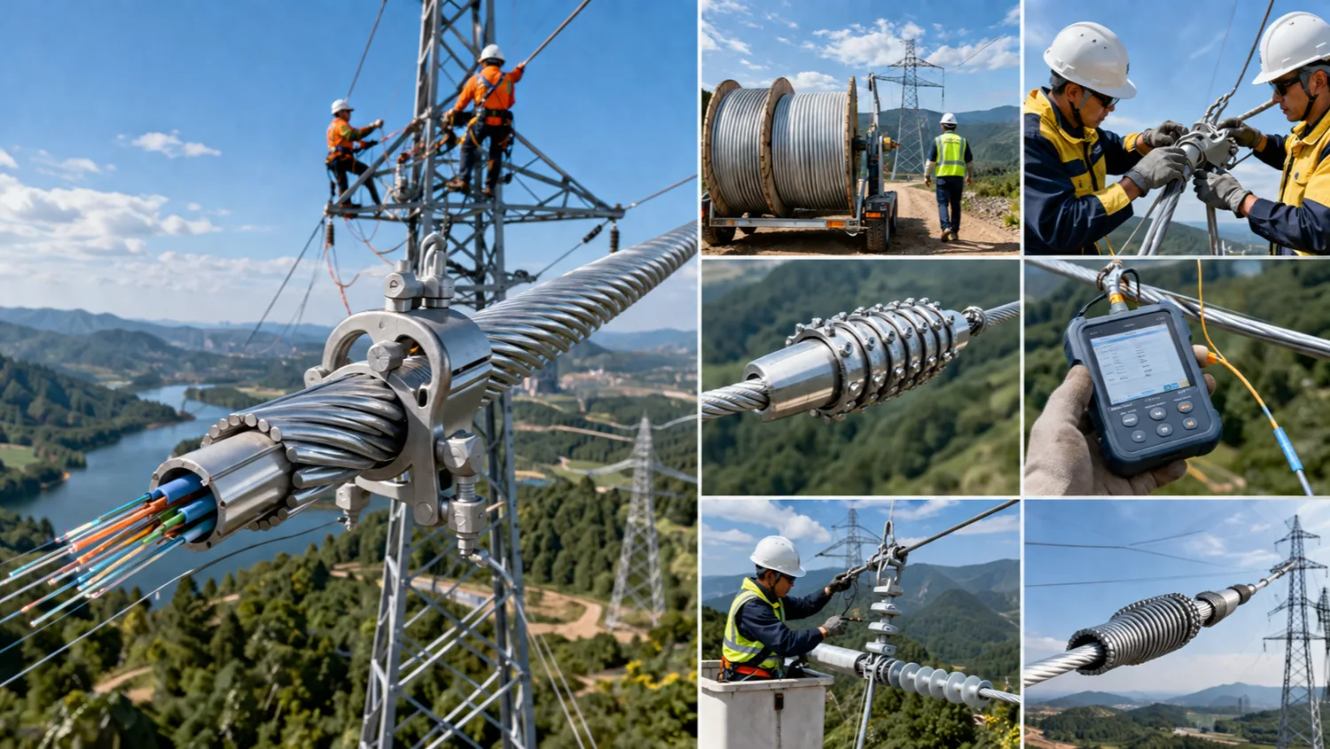
Successful OPGW deployment demands careful planning from a field execution standpoint. Installation typically requires line outages, as the cable replaces or augments existing ground wires using stringing equipment, tensioners, and pullers calibrated to the cable's weight and RTS.
Key practices include:
- Sag and tension calculations accounting for thermal expansion and ice/wind loads
- Proper grounding at each tower to maintain electrical integrity
- Splicing optical fibers in weatherproof closures with low-loss fusion splices (<0.05 dB)
- Post-installation OTDR testing to verify attenuation budgets
Maintenance involves periodic visual inspections, corrosion assessments on metallic layers, and optical performance monitoring. Unlike all-dielectric cables, OPGW requires attention to grounding continuity but offers robust mechanical protection. Crews appreciate the consolidated maintenance scope—one asset instead of multiple. Best practices emphasize matching cable specifications precisely to the line's ruling span and fault levels to avoid premature aging.
7. Comparison with Alternative Technologies (e.g., ADSS)
When evaluating OPGW cable against alternatives like ADSS (All-Dielectric Self-Supporting), practical trade-offs become clear. ADSS is lightweight, non-conductive, and suitable for live-line installation near energized conductors, making it ideal for retrofits without outages. However, it lacks inherent grounding capability, requiring a separate ground wire.
Table 3: OPGW vs ADSS Cable – Performance Comparison
|
Feature |
OPGW Cable |
ADSS Cable |
Winner / Best Use Case |
|
Primary Function |
Grounding + Communication |
Communication only |
OPGW for HV lines |
|
Construction |
Metallic (Al/Steel + Fiber) |
All-Dielectric (Aramid/FRP) |
ADSS for live-line installation |
|
Lightning / Fault Protection |
Excellent (handles high kA) |
None (requires separate ground wire) |
OPGW |
|
Typical Span Length |
200 - 1200 m |
500 - 1500+ m |
ADSS for long spans |
|
Weight |
400 - 1200 kg/km |
100 - 250 kg/km |
ADSS (lighter load on towers) |
|
Installation |
Requires outage |
Live-line possible |
ADSS for retrofits |
|
EMI Immunity |
Good (with proper grounding) |
Excellent |
ADSS |
|
Voltage Level Suitability |
≥ 110 kV (ideal for 220-765 kV) |
10 - 500 kV |
OPGW for ultra-high voltage |
|
Typical Fiber Capacity |
12 - 144+ |
12 - 288 |
Similar |
|
Lifespan |
30 - 40+ years |
20 - 30 years |
OPGW |
OPGW excels in high-voltage applications needing combined protection and communication. Its heavier construction provides better sag performance under icing and superior lightning shielding, though it demands de-energized installation and potentially tower reinforcements. Electrically, OPGW handles fault currents that ADSS cannot. For utilities prioritizing grid protection alongside data, OPGW delivers superior long-term value despite higher upfront complexity.
Other electric cable options, such as traditional ACSR ground wires, offer no communication pathway, forcing parallel fiber deployments that increase right-of-way usage and costs. OPGW's hybrid nature positions it as the optimized choice for comprehensive transmission line modernization.
8. Future Outlook: Why Power Grids Cannot Afford to Ignore OPGW
Looking ahead to 2026 and beyond, OPGW cables are pivotal for smart grid evolution, renewable integration, and grid digitalization. Rising fiber counts and embedded sensing capabilities will support AI-driven predictive maintenance and autonomous grid operations. Market growth reflects this necessity, driven by aging infrastructure replacement and expanding ultra-high-voltage networks.
From an engineering and operational viewpoint, power grids facing increasing extreme weather, cyber threats, and load variability need the reliability and bandwidth OPGW provides. Partnering with an experienced opgw cable manufacturer ensures tailored solutions meeting international standards.
In conclusion, OPGW is far more than an advanced wires and cable technology—it is a foundational element enabling resilient, intelligent power grids. Utilities investing in it today secure operational excellence and future readiness in an electrified world.
FAQ
Q1: What is an OPGW cable?
A: OPGW cable, also known as Optical Ground Wire or Optical Fiber Composite Overhead Ground Wire, is a dual-function cable that serves as both a traditional ground wire for lightning protection and a high-capacity optical fiber cable for data transmission. It is widely used in high-voltage power grids to combine electrical grounding with reliable communication.
Q2: What is the difference between OPGW cable and ADSS cable?
A: OPGW cable is a metallic hybrid design that provides grounding and fault current carrying capability, making it ideal for high-voltage transmission lines (≥110 kV). In contrast, ADSS is an all-dielectric, non-conductive cable that is lighter and suitable for live-line installation but does not replace the ground wire. OPGW is preferred when both protection and communication are required in one cable.
Q3: Why do power grids need OPGW cables?
A: Power grids need OPGW cables because they improve grid reliability by offering lightning protection, fast fault detection, and high-speed communication for smart grid applications. They reduce infrastructure costs by combining grounding and fiber optic functions, support renewable energy integration, and enable real-time monitoring essential for modern transmission lines.
Q4: What are the typical specifications of OPGW fiber cable?
A: Typical OPGW fiber cable specifications include 12 to 144 optical fibers, attenuation ≤0.21 dB/km at 1550nm, short-circuit capacity of 20–200 kA²s, and tensile strength up to 700 kN. The cable diameter ranges from 10–30 mm, with operating temperatures from -40°C to +80°C, compliant with IEEE 1138 and IEC standards.
Q5: How is OPGW cable installed on transmission lines?
A: OPGW cable installation usually requires a line outage. The process involves stringing the cable using tensioners and pullers, followed by sag-tension adjustment, fiber splicing in closures, and OTDR testing. Proper grounding at each tower is critical to maintain electrical performance and safety.
Q6: Who are the leading OPGW cable manufacturers?
A: Leading opgw cable manufacturers include Prysmian, ZTT, Fujikura, LS Cable & System, and APAR. When selecting a manufacturer, utilities should focus on compliance with international standards, custom engineering capabilities, and proven track records in high-voltage projects.
Related Articles
Related Products
75kVA Conventional Type Single Phase Pole Mounted Transformer
NPC ELECTRIC has been specialized in manufacturing 75kVA Conventional Type Single Phase pole Mounted transformer for more than 20 years, which complies with international standards such as ANSI/IEEE C57, IEC60076 and other standards. Its main function is to convert high voltage electricity (such as 11kV, 13.8kV, etc.) into low voltage electricity (such as 120V/240V), providing stable and reliable power supply to end users. It is suitable for residential, commercial, agricultural and small industrial loads. Typical specifications include mineral oil insulation (ONAN cooling), aluminum or copper windings, primary voltages 2.4kV–34.5kV grounded wye or delta (common: 7200/12470GrdY, 7620/13200GrdY, 12470GrdY/7200, 24940GrdY/14400, 34500GrdY/19920), secondary 120/240V or 240/120V split-phase, BIL ratings 95–150kV HV / 30kV LV, impedance typically 2.0–4.0%, ±2×2.5% or 5-position tap changer, conventional or CSP (completely self-protected) configurations with internal fuses, lightning arresters, weak-link protection, pressure relief valve, oil sight gauge, and ANSI 70 gray tank finish. Efficiency typically reaches 99.17–99.19% at 50% load per DOE levels, with low sound levels and corrosion-resistant hardware for extended outdoor service.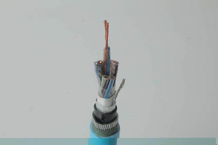
Instrumentation Cables—PVC Insulated, Overall Screened, Wire Armoured PVC Sheathed Cables(CU/PVC/OSCR/SWA/PVC)
Instrumentation Cables are multi-conductor cables that carry and transport low-voltage electrical signals. These low-voltage signals are used to control and monitor electrical power systems. Instrumentation cables have many different industrial applications that include broadcasting, equipment control, such as drilling and pumping in the oil and gas industry, and data transfer, which includes analog and digital signals. They are manufactured according to the BS EN 50288-7 and BS EN 50288-1 standards to ensure quality. Depending on the application, instrumentation cables can be insulated with PVC or XLPE; the cables can be armoured or unarmoured. The sheathing materials can be of PVC, LSZH, or PE. The cables can have additional flame retardant or flame retardant properties, and they can be manufactured with special protections such as lead sheaths, or DRYLAM or AIRBAG technology.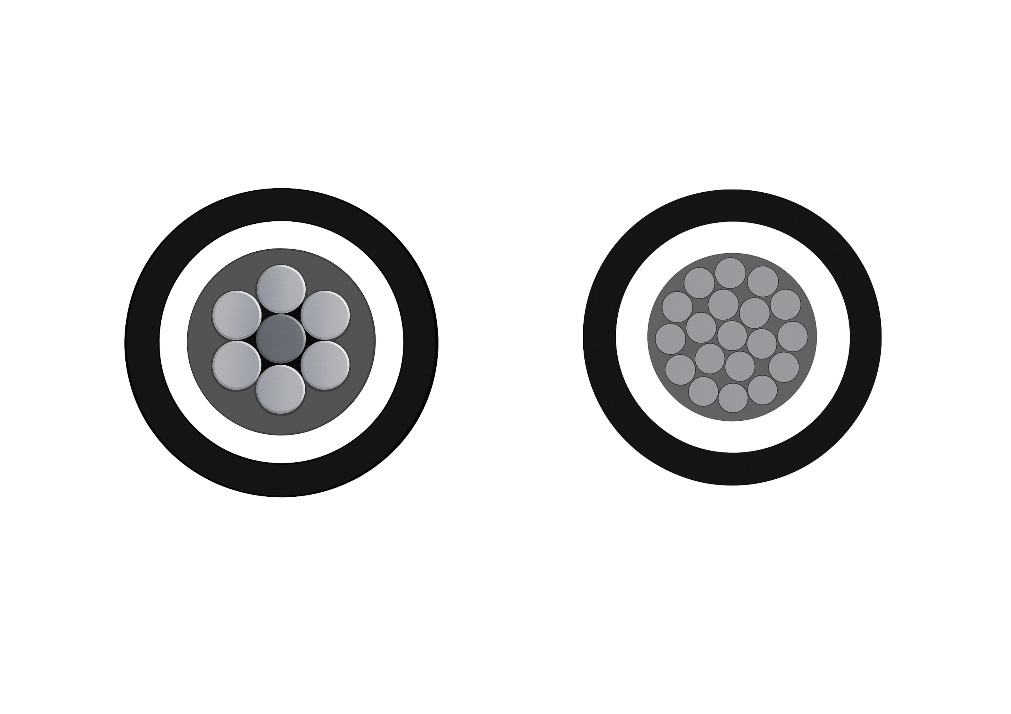
3-Layer 46kV Tree Wire - Covered Overhead MV Cable
The 3-Layer 46kV AAAC/ACSR/AAC Tree Wire is a premium covered medium-voltage overhead conductor designed for reliable performance in heavily vegetated environments. It features a concentrically stranded AAAC, ACSR, or AAC conductor protected by a robust triple-layer system of track-resistant high-density polyethylene (HDPE) or cross-linked polyethylene (XLPE). The multi-layer covering delivers exceptional tracking resistance, abrasion protection, and weatherability while significantly reducing the risk of electrical faults from tree limb contact and minimizing wildfire ignition potential. This advanced design allows closer spacing to vegetation and lowers vegetation management costs. Suitable for both conventional overhead lines and spacer cable systems, the 3-Layer 46kV AAAC/ACSR/AAC Tree Wire meets ICEA S-121-733 and related ASTM standards. It undergoes rigorous quality testing from raw materials to finished product, ensuring excellent dielectric strength, mechanical robustness, and long-term durability in demanding high-voltage applications.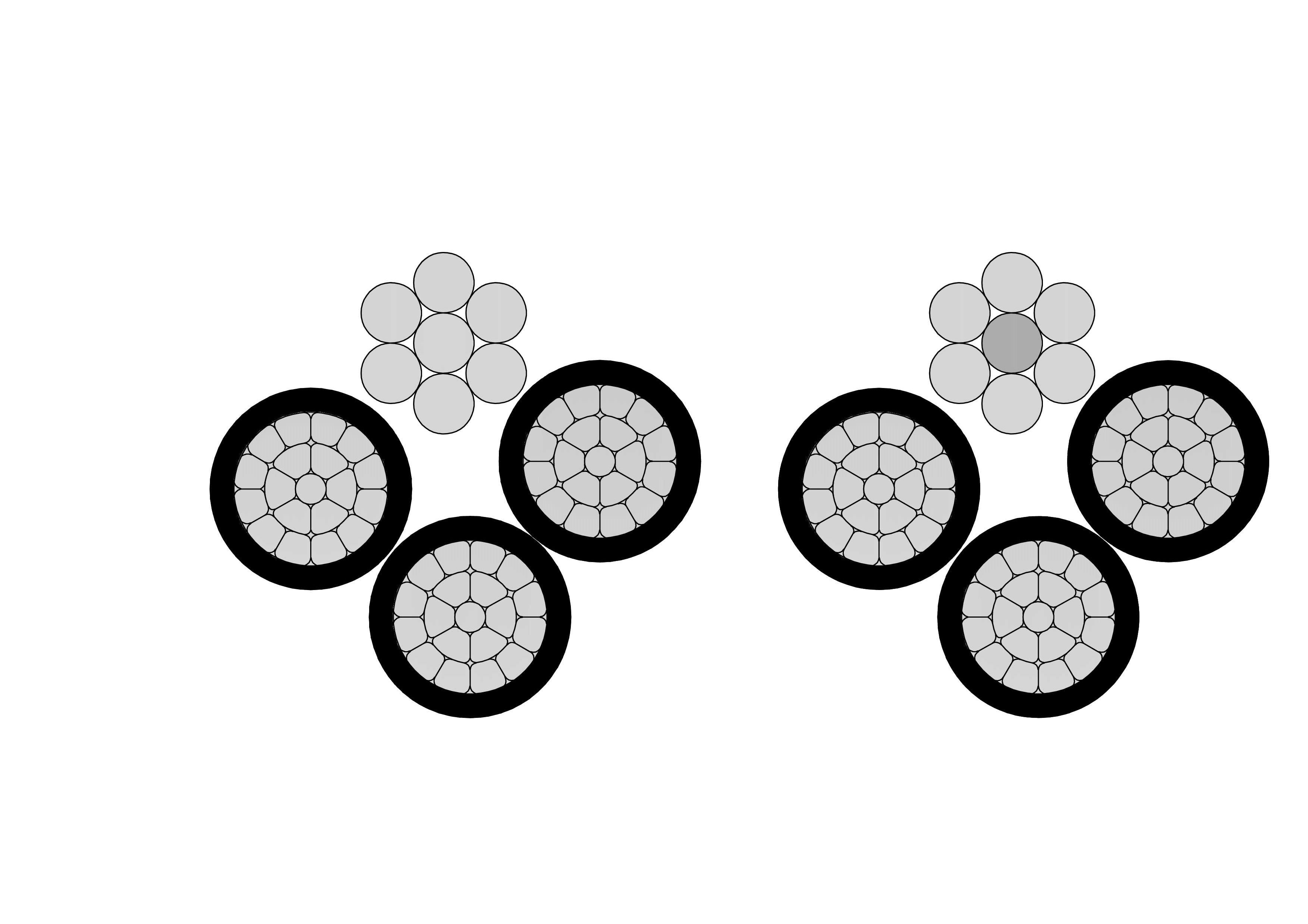
4/0 Appaloosa Aluminum Conductor Quadruplex Overhead Service Drop Cable
Our 4/0 Appaloosa Quadruplex Service Drop Cable delivers efficient overhead three-phase service with neutral support. Comprising three 4/0 AWG aluminum phase conductors (7-strand) insulated with XLPE or PE and helically twisted around a strong neutral messenger (ACSR or aluminum), it meets ASTM, ICEA, and international standards. The messenger provides full self-support, allowing longer spans and reduced infrastructure costs. Premium insulation resists sunlight, moisture, and mechanical abrasion for decades of outdoor service. Lightweight and flexible, it simplifies installation with low sag. The 4/0 Appaloosa Quadruplex Service Drop Cable ensures minimal losses, high mechanical endurance, and excellent weather performance up to 600V. Flame-retardant options enhance safety. Perfect for reliable power delivery in urban developments, commercial areas, street lighting, and temporary sites requiring safe, cost-effective aerial bundled quadruplex solutions.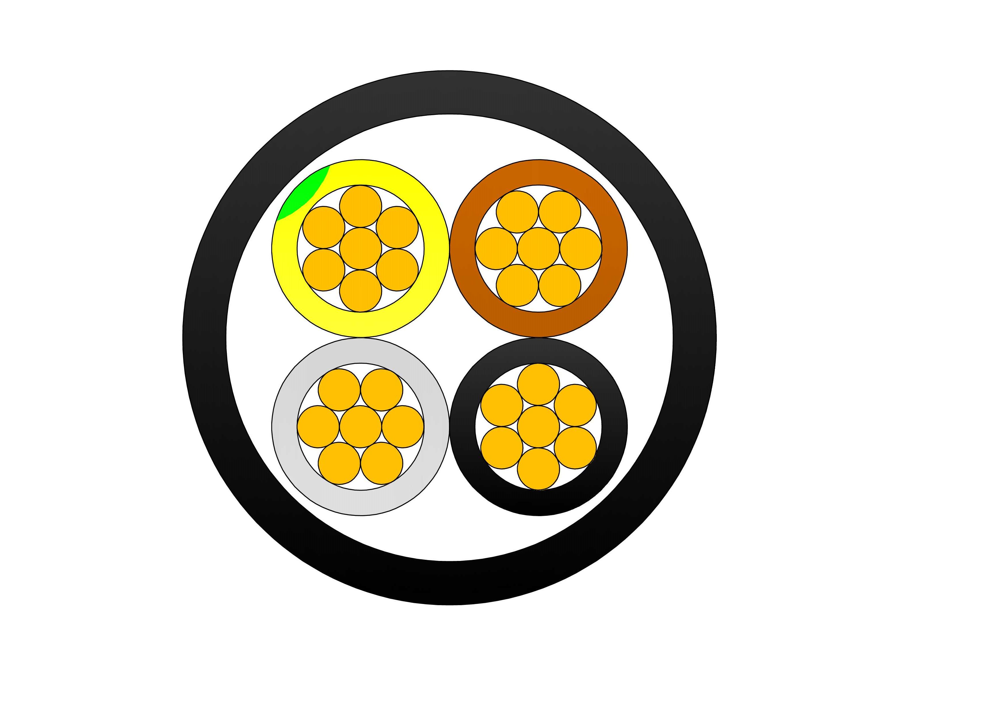
3+1 Cores Copper Cable CU/XLPE/PVC 0.6/1kV
The 3+1 Cores Copper Cable CU/XLPE/PVC 0.6/1kV is a high-performance low-voltage power cable designed for reliable electrical power transmission and distribution systems. Featuring three phase conductors and one neutral conductor, this cable is manufactured with high-purity copper conductors, cross-linked polyethylene (XLPE) insulation, and a durable PVC outer sheath. The combination of premium materials ensures excellent electrical conductivity, thermal stability, and mechanical protection. XLPE insulation provides superior dielectric properties, higher operating temperatures, and enhanced resistance to moisture, chemicals, and aging compared with conventional PVC-insulated cables. The PVC outer sheath offers excellent protection against abrasion, impact, and environmental conditions, making the cable suitable for indoor, outdoor, duct, tray, and underground installations. Designed to operate at rated voltages up to 0.6/1kV, this cable is widely used in industrial plants, commercial buildings, renewable energy projects, utility substations, and infrastructure developments. Manufactured according to international standards, the cable delivers long service life, reliable performance, and enhanced safety in demanding electrical distribution applications.
160 kVA Three Phase Cast Resin Dry Type Transformer Low Loss Energy Efficient
The 160 kVA Three Phase Cast Resin Dry Type Transformer Low Loss Energy Efficient is a state-of-the-art, maintenance-free power solution engineered for indoor installations where safety, reliability, and sustainability are paramount. Encased in high-quality epoxy resin under vacuum pressure, its windings deliver outstanding moisture resistance, superior partial discharge performance, and fire-retardant self-extinguishing properties without flammable liquids. Utilizing premium grain-oriented silicon steel cores and optimized conductor designs, this transformer achieves significantly reduced no-load and load losses, attaining high efficiency levels often exceeding 98.5% and complying with stringent energy regulations. With natural air (AN) cooling, low acoustic emissions below typical 58-62 dB, and Class F or H insulation, it ensures stable operation in harsh indoor environments. Fully compliant with IEC 60076-11, this compact, eco-conscious dry-type unit supports primary voltages like 10kV/11kV/20kV/35kV stepping down to 0.4kV or custom secondaries, making it ideal for modern, green power distribution networks.
33kV Cast Resin Dry Type Transformer 1000kVA–5000kVA Three Phase
The 33kV Cast Resin Dry Type Transformer 1000kVA–5000kVA Three Phase is a high-capacity, oil-free power solution engineered for demanding indoor medium- and high-voltage distribution networks. This robust three-phase cast resin transformer utilizes premium low-loss grain-oriented silicon steel cores and high-conductivity copper windings (aluminum optional) fully encapsulated in high-grade epoxy resin under vacuum pressure, delivering exceptional energy efficiency (typically 98.5–99.5%), significantly reduced no-load and load losses, and superior partial discharge performance (<10pC). Fully compliant with IEC 60076-11, IEEE/ANSI, and relevant energy efficiency standards, this transformer steps down 33kV primary (with ±2×2.5% to ±10% off-circuit taps standard) to secondary voltages such as 0.4kV, 0.69kV, 6.6kV, or 11kV (Dyn11 vector group typical).
100kV 200kVA 250kVA 315kVA Three-Phase Oil-Immersed Substation Power Transformer
This 100kV three-phase oil-immersed substation power transformer is engineered for stable voltage transformation across 200kVA, 250kVA, and 315kVA capacity ranges. Designed for medium to high-voltage distribution networks, it delivers exceptional reliability, thermal endurance, and operational efficiency in substations, industrial plants, and utility distribution grids. The transformer utilizes high-grade insulation, precision-wound copper conductors, and robust core materials to ensure low losses, long service life, and consistent performance under demanding electrical and environmental conditions. Its sealed oil-immersed structure enhances insulation strength and optimizes heat dissipation for safe and continuous operation.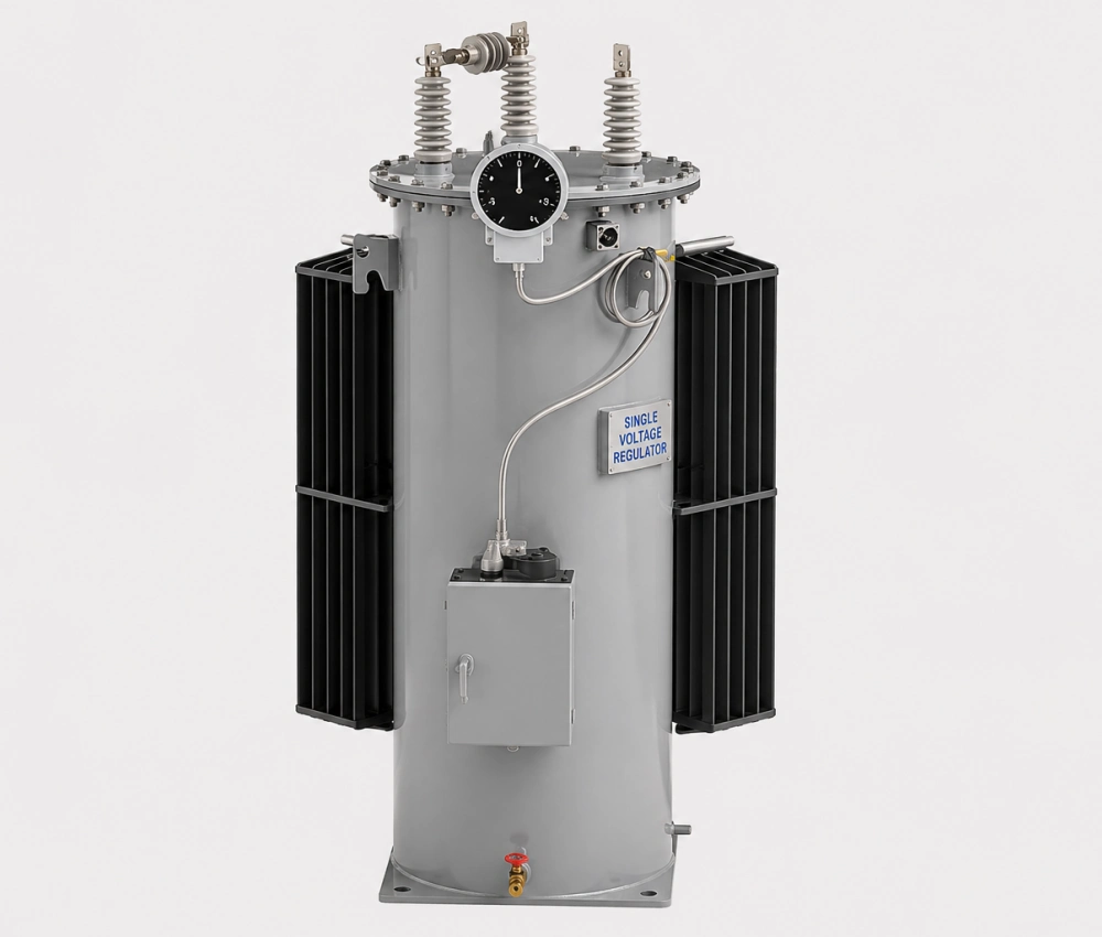
Three Phase Automatic Step Voltage Regulator
The Three Phase Automatic Step Voltage Regulator is a high-performance on-load tap changing device designed to automatically maintain stable voltage levels in medium-voltage distribution networks. Equipped with premium copper windings, low-loss silicon steel cores, and a reliable motorized on-load tap changer, it delivers fast, precise voltage correction with minimal waveform distortion. The intelligent digital controller continuously monitors three-phase voltage and load conditions, making real-time adjustments to ensure consistent output voltage despite fluctuations in supply or demand. Built for outdoor durability, it features a fully sealed oil-immersed tank with advanced corrosion protection, excellent overload capability, and comprehensive protection systems. This regulator significantly improves power quality, reduces line losses, and enhances equipment lifespan across distribution systems.
11/0.4kV 630kVA Oil-Immersed Power Transformer Distribution Type
Discover our premium 11/0.4kV 630kVA Oil-Immersed Power Transformer, engineered for superior high-efficiency distribution in modern electrical grids. This robust transformer features advanced silicon steel cores that minimize energy losses, ensuring up to 98% efficiency under full load. Ideal for urban and rural power networks, it incorporates eco-friendly insulating oil with high dielectric strength, providing reliable voltage step-down from 11kV to 0.4kV while handling demanding loads up to 630kVA. Built with corrosion-resistant tanks and precision-wound copper coils, this distribution transformer guarantees long-term durability, reduced maintenance, and compliance with international standards like IEC 60076. Whether for residential complexes, commercial facilities, or industrial applications, it optimizes power delivery, lowers operational costs, and supports sustainable energy practices. Experience unmatched performance with this high-efficiency oil-immersed transformer designed for seamless integration into your power system.
XLPE-HDPE Tree Cable Aluminum 25kV 1x185mm²
Power your network with confidence using the XLPE-HDPE Tree Cable Aluminum 25kV 1x185mm² – a high-performance medium-voltage cable engineered for demanding overhead distribution systems. Whether it’s industrial zones, main feeder lines, or expansive urban and rural networks, this cable delivers reliable, efficient, and uninterrupted power where you need it most. Built with high-conductivity aluminum alloy 1350 wires and compact class 2 stranding, it guarantees optimal current flow and mechanical strength. Optional semiconductor shielding enhances electrical stability for 15kV and 25kV networks, making it a dependable choice for modern power infrastructure. The XLPE inner insulation withstands 90°C continuous operation, while the robust HDPE outer jacket offers exceptional resistance to weather, UV exposure, mechanical abrasion, and electrical sparking. Available in gray with ASTM B230 markings and sequential metering, or blue for extra spark resistance in harsher environments, this cable is designed to perform under pressure.
161kV 50MVA Two-Winding Power Transformer – Efficient Oil-Filled Design with OLTC
The 161kV 50MVA Two-Winding Power Transformer is engineered to deliver precise voltage control and stable power transfer in high-voltage transmission and substation networks. Featuring an oil-filled insulation system combined with an On-Load Tap Changer (OLTC), this transformer allows continuous voltage adjustment under load conditions without interrupting system operation. The electromagnetic design emphasizes low losses, high operational efficiency, and consistent performance across variable load profiles. Robust mechanical construction enhances resistance to thermal expansion and short-circuit forces, ensuring long-term reliability in demanding grid environments. Optimized oil circulation supports effective heat dissipation, contributing to extended service life and reduced maintenance requirements. This transformer is well suited for modern power systems where voltage stability, operational flexibility, and dependable energy transmission are critical.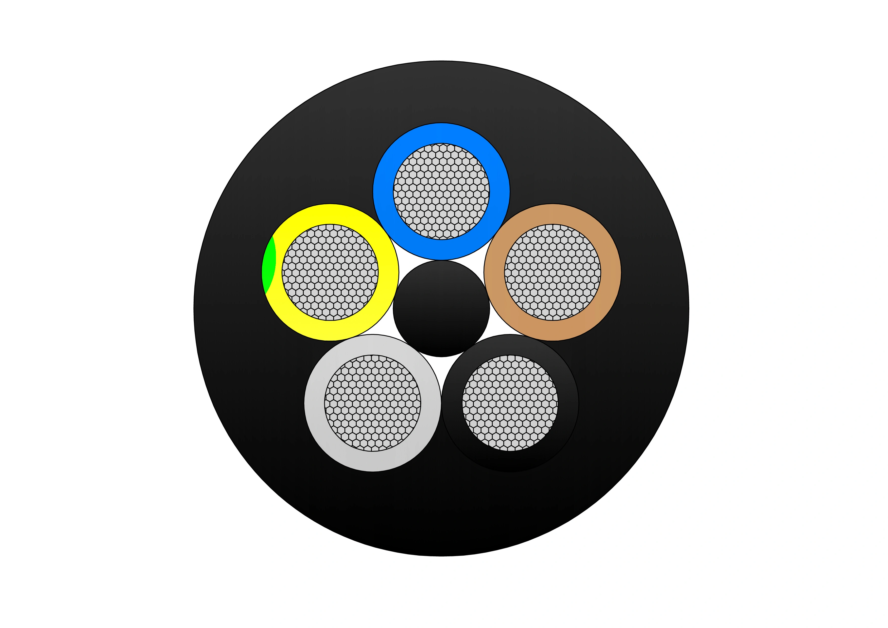
NTSCGECECWOU 3.6/6kV and 6/10kV Cable
The NTSCGECECWOU 3.6/6kV and 6/10kV cable is a flexible medium voltage power cable manufactured to VDE 0250 Part 813 standards, designed for reeling and trailing applications in mining, tunneling, and other demanding industrial environments. Constructed with Class 5 tinned copper conductors, EPR insulation, and a robust halogen-free sheath, it delivers exceptional mechanical strength, flame retardancy, oil resistance, and flexibility. Its copper wire screen ensures EMC protection, while the rugged sheath withstands extreme temperatures, making it suitable for both indoor and outdoor installations in harsh conditions.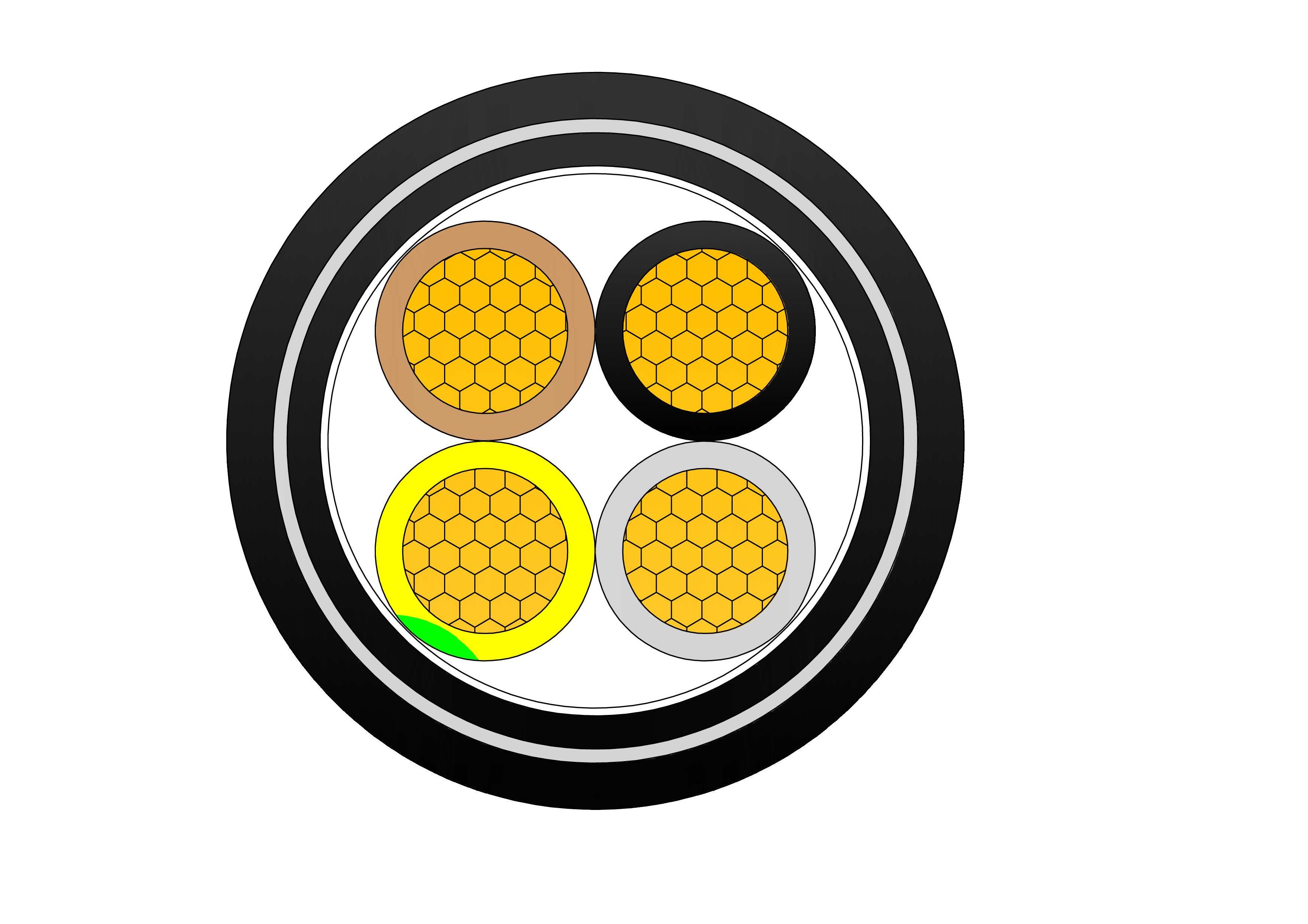
N2XBY 0.6/1kV Low Voltage Power Cable
N2XBY 0.6/1kV are low voltage power cables designed according to BS 5467 standard, suitable for fixed installation in indoor, outdoor, underground, Cable ducts or conduits, or concrete (not subject to vibration) environments. Featuring stranded copper conductors, cross-linked polyethylene (XLPE) insulation, PVC bedding, galvanised steel wire armour (SWA), and PVC outer sheath, it fully complies with IEC 60502-1 standards. The steel wire armour provides excellent mechanical protection against impacts, rodents, and crushing forces, making it perfect for direct burial. Widely used in industrial plants, infrastructure projects, and utility networks requiring reliable, protected low-voltage power supply underground or outdoors.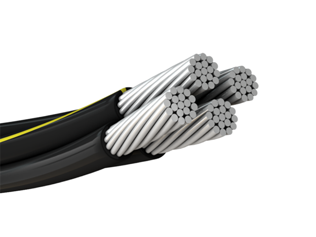
ABC CABLE NFC 33-209
Aerial Bundled Cable under NPC 33-209 standard is mainly used in the field of overhead power distribution. ABC Cable, manufactured in accordance with NFC 33-209 is designed for overhead low-voltage power distribution with enhanced mechanical strength and operational safety. The cable consists of insulated aluminum phase conductors twisted around a reinforced messenger conductor, forming a compact aerial bundle. This structure reduces the risk of short circuits caused by external contact and minimizes power outages in densely populated or environmentally challenging areas. The insulation material provides excellent resistance to UV radiation, weather exposure, and thermal aging, ensuring stable electrical performance over long service periods. Compliant with NFC 33-209 requirements, the cable delivers reliable current transmission, reduced line losses, and simplified installation compared with bare conductors. ABC Cable NFC 33-209 is widely used by utility companies for modern overhead distribution networks where safety, durability, and cost efficiency are critical.Welcome your inquiry
Honesty, Integrity, Frugality, Activeness and Passion