Grounding Transformer: How It Works, Benefits, and Why You Need It
2026-06-10
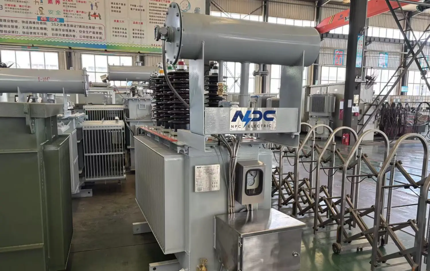
In modern electrical power systems, maintaining system stability and safety during ground faults remains critical, especially in ungrounded configurations common in industrial, utility, and renewable energy applications. A grounding transformer, also referred to as an earthing transformer, provides an artificial neutral point and establishes a controlled ground path. This ensures safe dissipation of fault currents and stabilizes phase voltage during abnormal conditions.
From an engineering and export perspective, grounding transformers are widely deployed in:
- Power distribution substations
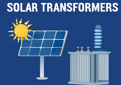
- Renewable energy plants (especially solar farm grounding transformer systems)
- Industrial plants with sensitive automation
Understanding the Fundamentals of Grounding Transformers
A grounding transformer connects to a three-phase power system lacking a naturally grounded neutral. It provides a ground reference without carrying significant load current under normal balanced conditions. The device primarily handles zero-sequence components that arise during line-to-ground faults or system imbalances.
From a practical engineering perspective, the transformer appears nearly invisible during normal operation. Its magnetizing current stays minimal because the windings are arranged to cancel positive- and negative-sequence fluxes. Only zero-sequence currents—those flowing equally in all three phases and returning through ground—encounter low impedance. This design principle allows the system to maintain balanced line-to-neutral voltages close to nominal values, typically limiting temporary overvoltages to safe levels below √3 times the normal phase voltage.
In field applications, such as medium-voltage collector systems, grounding transformers are installed at substations or directly on feeder circuits. They convert a three-wire ungrounded circuit into a four-wire, effectively grounded system, enabling phase-to-neutral loads where required and supporting sensitive protective relaying.
How a Grounding Transformer Works: Core Principles and Current Flow
The operating mechanism relies on symmetrical component theory. In a healthy system, positive- and negative-sequence currents produce opposing magnetic fluxes that largely cancel within the core, resulting in negligible excitation. During a single line-to-ground fault, zero-sequence current flows through the faulted phase, returns via ground, and enters the grounding transformer neutral.
Inside the transformer, this current divides among the windings and returns through the grounded neutral connection. The low zero-sequence impedance ensures sufficient fault current magnitude for protective devices to detect and clear the fault quickly, while still limiting it to prevent excessive damage.
Table 1: Grounding Transformer Sizing Parameters and Guidelines
|
Parameter |
Description |
Typical Values / Guidelines |
Importance in Practice |
|
Line-to-Ground Voltage |
Phase-to-neutral voltage of the system |
5.77 kV (for 10 kV system) |
Determines insulation and basic rating |
|
Neutral Current (IN) |
Ground fault current that the transformer must carry |
100 – 1000 A (short-time) |
Core sizing factor |
|
Duration |
The time the transformer can withstand a fault current |
10 seconds (most common), 30 seconds, 1 minute |
Thermal withstand capability |
|
Zero-Sequence Impedance (Z0) |
Impedance seen by zero-sequence current |
2% – 10% or 0.2 – 10 Ω/phase |
Affects fault current magnitude and protection |
|
Continuous Neutral Current |
Sustained unbalanced or harmonic current |
3% of 10-sec rating (IEEE Std 32) or 7% of 1-min |
Prevents overheating during normal operation |
|
X0/X1 Ratio |
For effective grounding |
≤ 3 (IEEE recommendation) |
Controls temporary overvoltage (TOV) |
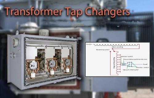
Two primary configurations dominate practical deployments:
Zigzag Earthing Transformer (Zig-Zag Grounding Transformer): Each core leg carries two half-windings from different phases, wound in opposite directions. For zero-sequence currents, the ampere-turns add constructively, creating a low-impedance path. For positive- or negative-sequence currents, the fluxes cancel, yielding high impedance. This makes the zigzag earthing transformer highly efficient and compact for pure grounding duties. It often proves more economical than alternatives for the same zero-sequence performance.
Wye-Delta Grounding Transformers (Grounded Wye-Delta): The primary connects in wye with the neutral grounded, while the secondary forms a closed delta (often unloaded). Zero-sequence current flows from the wye neutral through the windings and circulates within the delta, providing the return path. This setup offers flexibility for secondary loading, such as auxiliary power supply or metering, though it typically requires a larger core compared to zigzag designs for equivalent fault current handling.
Table 2: Zig-Zag vs Wye-Delta Grounding Transformers Comparison
|
Parameter |
Zig-Zag Grounding Transformer |
Wye-Delta Grounding Transformer (Grounded Wye-Delta) |
|
Winding Configuration |
Interconnected star (zig-zag) |
Wye primary (neutral grounded) + closed Delta secondary |
|
Zero-Sequence Impedance |
Typically lower (more efficient) |
Slightly higher |
|
Physical Size & Cost |
Smaller and more economical |
Larger, higher material cost |
|
Secondary Loading Capability |
Limited (usually none) |
Excellent (can supply auxiliary power or trap harmonics) |
|
Best Applications |
Pure grounding in ungrounded systems, solar farms, and industrial feeders |
Systems needing auxiliary LV supply or harmonic mitigation |
|
Fault Current Handling |
Excellent for short-term ratings |
Good, with added flexibility |
|
Typical Use in Solar Farms |
Preferred for collector systems |
Used when secondary functions are required |
In real-world operation, engineers calculate zero-sequence impedance (Z0) carefully. A lower Z0 allows higher ground fault currents for faster clearing, while a higher value (sometimes combined with a neutral resistor) limits damage in high-resistance grounded systems. For instance, in a 10kV grounding transformer application, the design must withstand short-time ratings—commonly 10 seconds or 1 minute—while maintaining continuous neutral current capability around 3-7% of the short-time rating per industry guidelines.
Zig-Zag vs Wye-Delta Grounding Transformers comparison reveals clear trade-offs. Zig-zag units usually feature a smaller size, lower cost, and reduced zero-sequence impedance, making them ideal when no secondary loading is needed. Wye-delta configurations excel in applications requiring an auxiliary delta winding for harmonic trapping or low-voltage supply, though they demand more material and insulation coordination. Selection depends on system voltage, expected fault levels, and whether ground isolation transformer characteristics or additional functionality matter.
Key Benefits of Installing Grounding Transformers
From an operational standpoint, grounding transformers delivers multiple-layered advantages that directly impact system reliability and safety:
- Fault Current Path and Protection: They supply a reliable return path for ground-fault zero-sequence currents, enabling overcurrent relays, directional ground relays, or residual current devices to detect and isolate faults selectively. Without this path, an ungrounded system might continue operating with a fault, elevating healthy phase voltages by up to 173% and risking insulation breakdown or arcing escalation.
- Voltage Stabilization and Transient Overvoltage Control: By keeping the neutral near ground potential, grounding transformers suppress transient overvoltages caused by restriking faults or switching events. This proves especially valuable in cable-heavy networks where capacitive charging currents interact with system inductance.
- Equipment and Personnel Safety: A controlled ground path reduces touch and step potentials, limits arc-flash energy in some configurations, and prevents floating potentials that could damage connected equipment or create shock hazards.
- System Compatibility and Load Support: In delta systems, they facilitate phase-to-neutral loading and improve compatibility with modern inverter-based resources that require stable voltage references.
- Harmonic Management: Certain configurations, particularly those with delta windings, help circulate and trap triplen harmonics, reducing distortion propagated through the network.
In practice, these benefits translate to longer equipment life, fewer unplanned outages, and compliance with grid codes for renewable interconnections.
Table 3: Benefits of Grounding Transformers in Different Applications
|
Application |
Primary Benefit |
Secondary Advantage |
Why a Grounding Transformer is Essential |
|
Solar Farm Collector System |
Limits TOV during ground faults |
Enables reliable inverter ride-through |
Prevents insulation stress in long cable runs |
|
Industrial Ungrounded Delta |
Provides fault detection path |
Supports phase-to-neutral loading |
Avoids undetected faults leading to phase-to-phase shorts |
|
Wind Farm / Renewable |
Stabilizes neutral reference |
Harmonic trapping (with delta winding) |
Meets grid code effective grounding requirements |
|
Improves relay sensitivity |
Reduces arc-flash energy in some configs |
Enhances personnel and equipment safety |
|
|
High-Resistance Grounded |
Controlled fault current limiting |
Minimizes equipment damage |
Allows continued operation with the first fault alarm |
Why You Need a Grounding Transformer: Practical Scenarios and Modern Applications
Ungrounded or delta-connected systems appear in many legacy industrial plants, generator step-up applications, and renewable energy collector circuits. Without grounding, a first ground fault may go undetected, leading to a second fault that creates a phase-to-phase short with potentially catastrophic results.
Solar Farm Grounding Transformer installations illustrate this need vividly. Large-scale photovoltaic plants often employ medium-voltage collector systems (e.g., 10kV to 35kV) configured as ungrounded delta to accommodate inverter output flexibility. A dedicated solar farm grounding transformer at the point of interconnection or on collector loops provides effective grounding, mitigates temporary overvoltages (TOV), and ensures inverters ride through faults without nuisance tripping. It also supports ground fault detection across long cable runs typical in solar arrays.
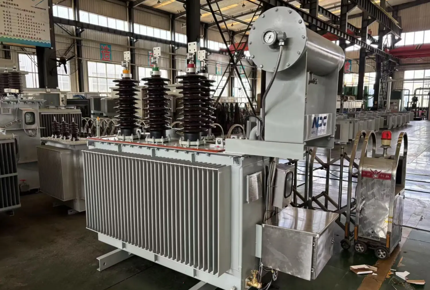
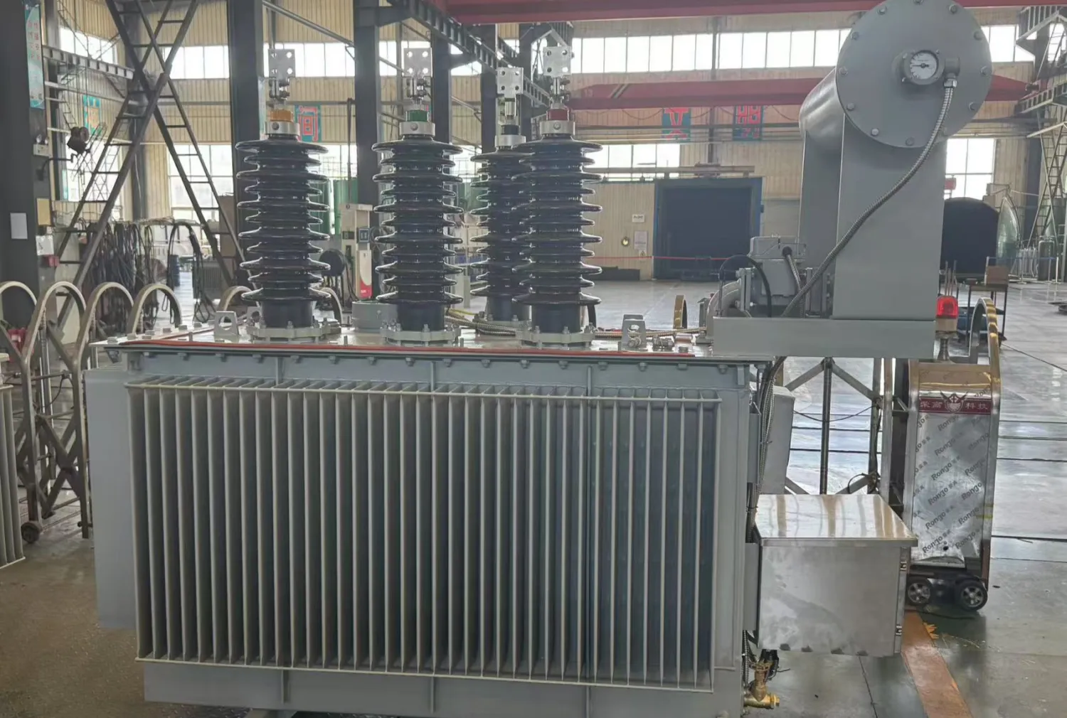
Similarly, in wind farms and industrial facilities with extensive underground cabling, grounding transformers prevent insulation stress and enable rapid fault location. For 10kV grounding transformer deployments common in Asia and Europe distribution networks, compact dry-type or oil-immersed units handle fault currents while fitting space-constrained substations.
Even in applications involving ground isolation transformer setups or ground bridge transformers, the core grounding function remains: creating a defined earth path without compromising galvanic isolation where needed. Terms like earth spark transformers occasionally appear in older literature but generally refer to the same zero-sequence handling role.
From a project execution viewpoint, specifying a grounding transformer early in design prevents costly retrofits. Engineers must evaluate system charging current, desired fault current limit (solidly grounded, low-resistance, or high-resistance), and short-time thermal ratings. For example, a transformer rated for 10 seconds at full fault current might carry only a small continuous neutral current, requiring careful coordination with protective settings.
Design Considerations from a Working Engineer’s Perspective
When selecting and applying grounding transformers, focus shifts to real-world performance:
- Sizing Methodology: Calculate based on line-to-ground voltage, desired neutral current (IN), and fault duration. For zigzag types, the kVA rating often equals (VLG × IN) / √3 for short-time duty. Include continuous rating margins for any sustained imbalance or harmonic loading.
- Impedance and Coordination: Target zero-sequence impedance that balances fault detection sensitivity with equipment withstand. Too few stress breakers; too high risks, undetected faults.
- Installation and Maintenance: Locate units near the system neutral point for minimal lead impedance. Ensure proper grounding of the tank and neutral conductor. Dry-type units suit indoor or harsh environments; oil-filled versions offer better cooling for higher ratings. Routine testing includes insulation resistance, turns ratio, and periodic dissolved gas analysis for oil units.
- Integration with Modern Systems: Inverter-based resources (solar, battery storage) introduce unique challenges like limited fault current contribution. Grounding transformers compensate by providing the majority of ground fault current, helping maintain effective grounding ratios (X0/X1 typically between 0 and 3 per IEEE guidelines).
- Common Variants: Beyond basic zigzag and wye-delta, hybrid designs or combinations with neutral reactors/resistors allow fine-tuning of fault current. Grounding transformer connection details—phase voltage ratings, ground path impedance, and high voltage wye delta transformers secondary loading—must align precisely with system parameters.
Secondary winding considerations matter when the unit doubles as a small power source. Ungrounded system integration requires verifying that the grounding transformer does not introduce unwanted circulating currents or resonance with system capacitance.
Table4: Typical Ratings for 10kV Grounding Transformer
|
System Voltage |
Neutral Current (Short-Time) |
Duration |
Approximate Short-Time kVA |
Continuous Neutral Current (Typical) |
Common Cooling Type |
|
10 kV |
200 A |
10 seconds |
350 – 600 kVA |
6 – 20 A |
Dry-type or Oil-immersed |
|
10 kV |
400 A |
10 seconds |
700 – 1200 kVA |
12 – 40 A |
Oil-immersed |
|
10 kV |
600 A |
10 seconds |
1000 – 1800 kVA |
18 – 60 A |
Oil-immersed |
|
10 kV |
1000 A |
10 seconds |
1700 – 3000 kVA |
30 – 100 A |
Oil-immersed |
Note: kVA calculation reference formula: Short-time kVA ≈ (Line-to-Ground Voltage × Neutral Current) / √3 (Zig-zag). The actual value depends on the zero-sequence impedance and the system charging current.
Table 5: Key Technical Specifications Checklist for Grounding Transformer Procurement
|
Specification Item |
Recommended Consideration |
Typical Range / Value |
Keyword |
|
Winding Configuration |
Zig-zag or Wye-Delta |
Zig-zag preferred for pure grounding |
Zigzag earthing transformer |
|
System Voltage |
Line-to-line / Line-to-ground |
10 kV, 20 kV, 35 kV |
10kV grounding transformer |
|
Short-Time Rating |
Current × Duration |
200–1000 A for 10 s |
|
|
Zero-Sequence Impedance |
Per phase |
0.2 – 10 Ω |
Ground path, zero sequence current |
|
Continuous Rating |
% of short-time rating |
3% (10 s) or 7% (1 min) |
Secondary loading, ungrounded system |
|
Cooling & Enclosure |
Dry-type vs Oil-immersed, Indoor/Outdoor |
Dry-type for harsh environments |
Ground isolation transformer |
|
BIL (Basic Impulse Level) |
Insulation coordination |
75 – 170 kV (for 10 kV class) |
High-voltage wye-delta transformers |
Conclusion: Investing in Grounding Transformers for Long-Term Reliability
A well-designed grounding transformer represents a modest investment that delivers outsized returns in safety, uptime, and equipment protection. Whether implementing a zigzag earthing transformer for cost efficiency or a wye-delta unit for added functionality, the technology addresses fundamental weaknesses of ungrounded systems while supporting the transition to renewable-heavy grids.
Project teams and operators who prioritize proper grounding from the conceptual stage avoid costly downtime and safety incidents. As power systems grow more complex with distributed energy resources, the role of grounding transformers, earthing transformers, and related neutral grounding solutions will only expand. Evaluating your specific voltage level, fault levels, and application—be it a 10kV industrial feeder or a multi-MW solar farm—ensures the chosen solution provides optimal performance throughout its service life.
Related Articles
Related Products
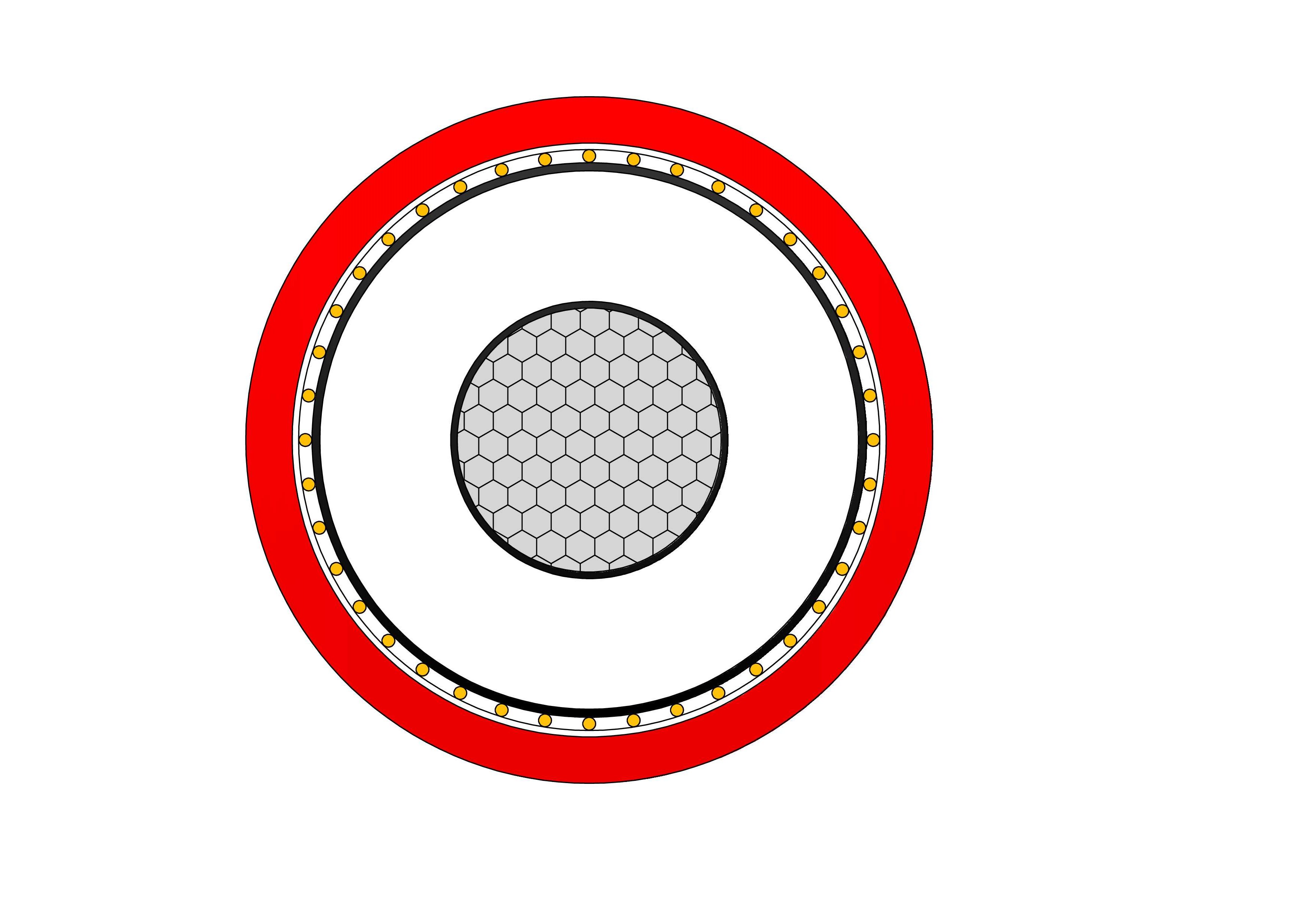
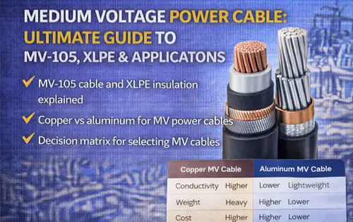
RHZ1-AL Medium Voltage Power Cable(8.7/15kV, 12/20kV, 18/30kV)
NPC Electric RHZ1-AL Medium Voltage Power Cable (8.7/15kV, 12/20kV, 18/30kV) provides economical fire safety for medium voltage networks. Built with aluminium conductors, thermosetting XLPE insulation, metallic screen, and advanced low smoke zero halogen (LSZH) sheath, it meets UNE 21123-4 and CPR requirements. During fires, it emits very low smoke and no corrosive gases, facilitating evacuation. Lightweight aluminium reduces costs and installation effort while delivering reliable current capacity. Superior partial discharge resistance, low tan delta, and thermal endurance ensure efficiency and longevity. Suitable for direct burial, ducts, or indoor use in sensitive areas, the RHZ1-AL Medium Voltage Power Cable is widely used in transportation hubs, data centers, public facilities, and infrastructure demanding reliable medium voltage cabling with enhanced fire protection, environmental compliance, and life-safety features in populated or confined spaces.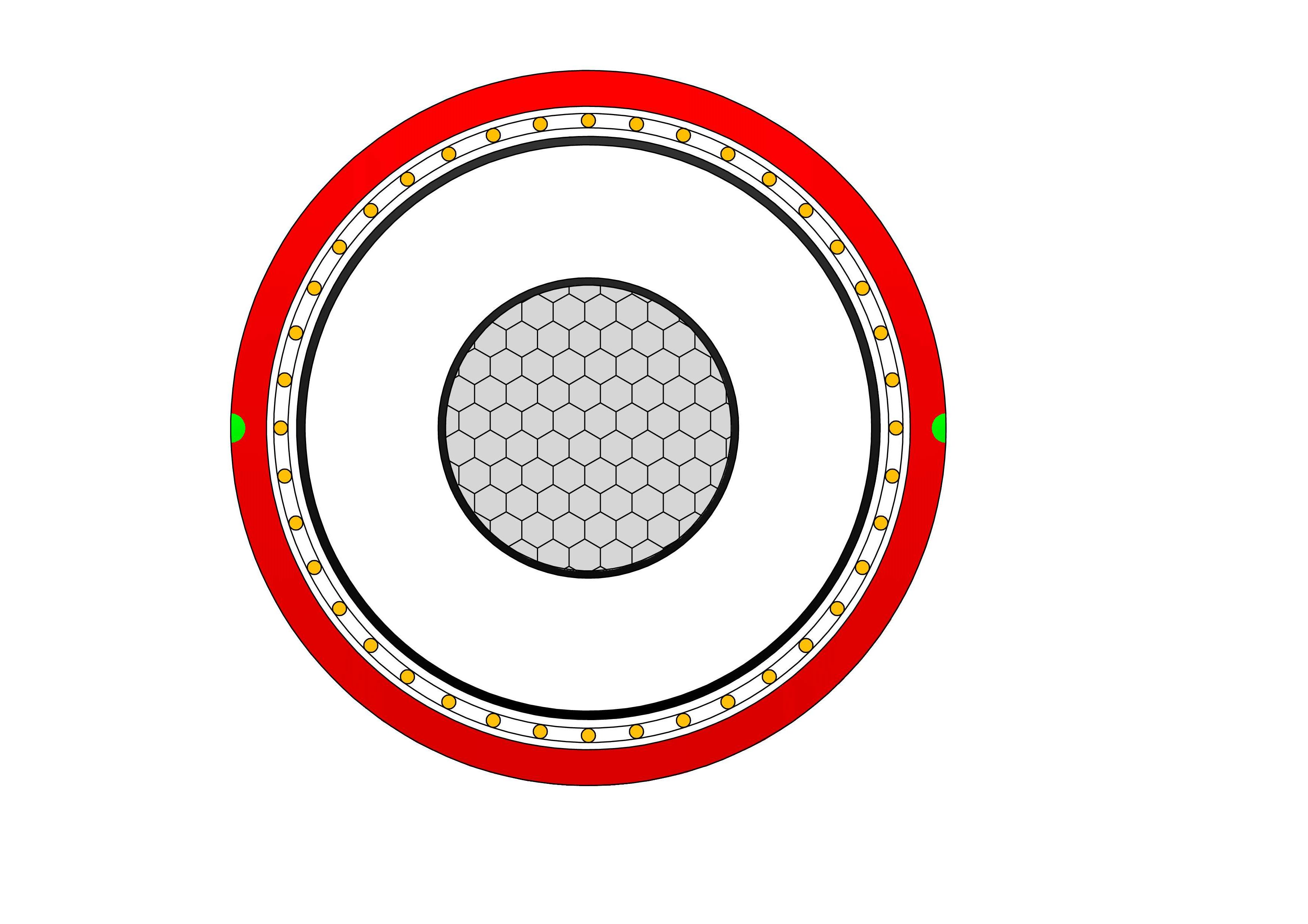
RHZ1-2OL-AL Medium Voltage Power Cable(8.7/15kV, 12/20kV, 18/30kV)
RHZ1-2OL-AL Medium Voltage Power Cable (8.7/15kV, 12/20kV, 18/30kV) is an economical, fire-safe cable for medium voltage distribution. Featuring stranded aluminium conductors, cross-linked polyethylene (XLPE) insulation, metallic screen, and low smoke zero halogen (LSZH) outer sheath, it complies with UNE 21123-4 and CPR standards. In fire conditions, the LSZH sheath emits minimal smoke and no toxic halogen gases, ensuring safety in populated areas. Lightweight aluminium reduces costs and handling effort while providing reliable current capacity. Superior partial discharge resistance, low dielectric losses, and high thermal stability guarantee efficient, long-lasting performance. Suitable for direct burial, ducts, or indoor installations. The RHZ1-2OL-AL Medium Voltage Power Cable is widely used in utilities, hospitals, schools, tunnels, and infrastructure projects requiring cost-effective, environmentally friendly medium voltage cabling with enhanced fire safety and durability worldwide.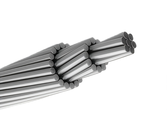
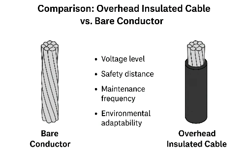
954 MCM RAIL ACSR Conductor Cable
The ACSR CAA 954 MCM 45/7F RAIL is a robust Aluminium Conductor Steel Reinforced (ACSR) cable designed to meet the demanding requirements of modern overhead transmission and distribution systems. It consists of 45 hard-drawn 1350-H19 aluminium strands concentrically wound around 7 galvanized steel strands, forming a high-capacity conductor with a reliable strength-to-conductivity ratio. Manufactured in accordance with ASTM B232, the RAIL configuration is ideal for long-span installations where increased tensile strength and environmental durability are essential. The galvanized steel core, coated to Class A or B standards, provides corrosion resistance and mechanical reinforcement against environmental stressors like wind, ice loading, and mechanical tension. This ACSR design supports efficient power delivery across overhead transmission networks, while also serving as a dependable solution for primary and secondary distribution lines. Suitable for voltages up to 230kV in distribution lines, the Rail ACSR Conductor Cable minimizes line losses and withstands harsh weather, including wind and ice loading.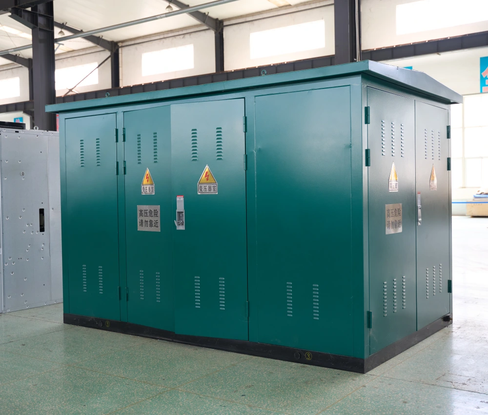
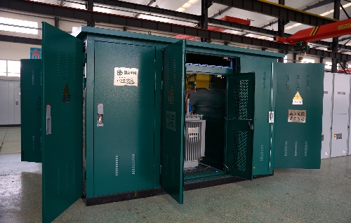
Outdoor Prefabricated Transformer Substation
The Outdoor Prefabricated Transformer Substation is an integrated medium-voltage power distribution solution designed for outdoor installation in industrial, commercial, utility, and renewable energy applications. The system combines medium-voltage switchgear, distribution transformer, low-voltage distribution equipment, and intelligent control systems into a compact prefabricated enclosure, providing efficient and reliable power transformation while minimizing construction time and installation costs. Engineered for harsh environmental conditions, the outdoor substation features a weather-resistant enclosure, corrosion-protected structure, advanced insulation technology, and optimized thermal ventilation system to ensure long-term operational stability. Its modular design allows rapid deployment, simplified transportation, and flexible installation while improving maintenance accessibility and operational safety. The Outdoor Prefabricated Transformer Substation supports multiple voltage levels, transformer capacities, and intelligent automation functions, making it suitable for utility distribution systems, renewable energy projects, urban infrastructure, mining facilities, transportation networks, and industrial manufacturing plants. With smart-grid compatibility and customizable configurations, the substation provides efficient and scalable electrical distribution performance for modern power networks.2Y-high-voltage-power-cable-2.webp)
2XS(FL)2Y MDPE High Voltage 36/60 (72.5)kV Power Cable
The 2XS(FL)2Y MDPE High Voltage Power Cable is a single-core aluminum conductor cable with XLPE insulation and an MDPE sheath, rated 36/60 (72.5) kV. Designed for high-voltage power transmission, it complies with IEC 60840 standards, delivering excellent electrical performance, robust mechanical protection, and outstanding water resistance for demanding applications. Its construction features a copper conductor, semi-conductive conductor screen, XLPE insulation, semi-conductive insulation screen, semi-conductive water swelling tape, copper wire metallic screen, longitudinal aluminum tape with PE copolymer coating, and a durable MDPE sheath. The water-blocking tape prevents water propagation inside the cable, ensuring reliable operation in power stations, industrial facilities, and distribution networks. This cable is suitable for distribution networks, connections to generation units, and industrial plants, with installation options including underground, underwater, outdoor, indoor, and cable ducts.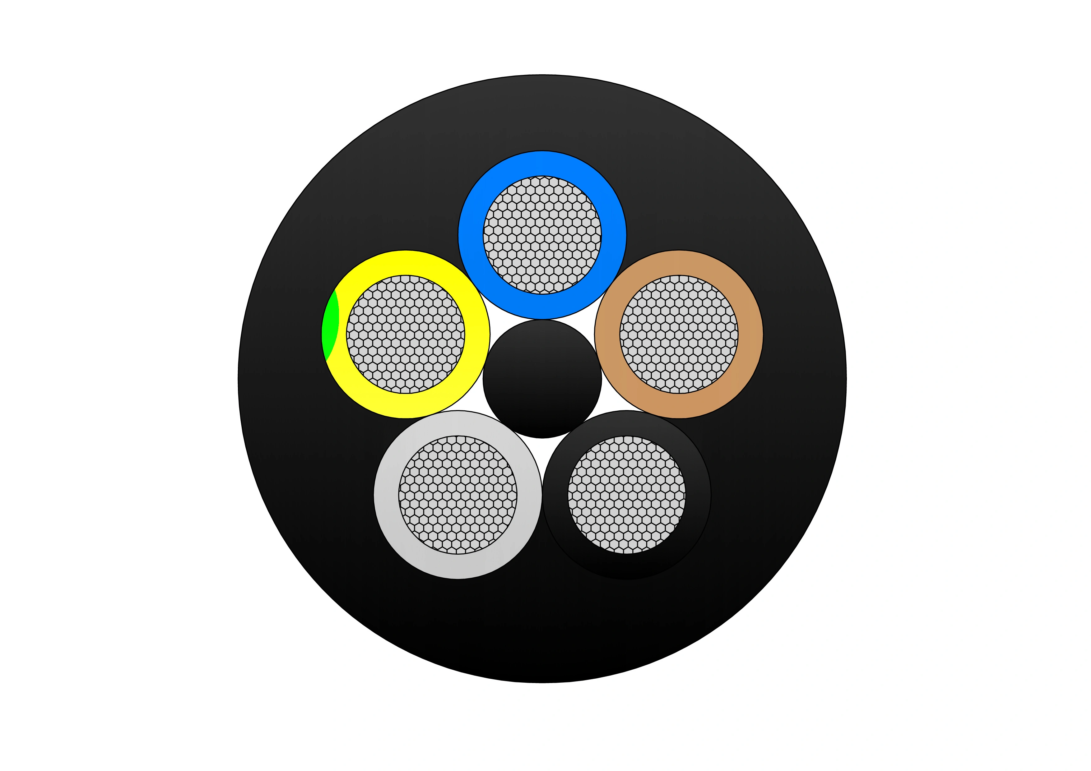
YSLTOE-J 300/500V Cable
The YSLTOE-J 300/500V Cable is a flexible low-voltage control cable featuring tinned copper conductors and a halogen-free, oil-resistant PUR outer sheath. It is engineered for gravity-feed collector baskets in modern high-speed container cranes, ensuring reliable performance under moderate mechanical stress and in oily industrial environments. Manufactured to DIN VDE 0281 and related standards, it offers excellent tensile strength, abrasion resistance, and flexibility. For proper installation, the cable must be mounted torsion-free in a counter-clockwise direction, with a basket diameter exceeding 30× the cable’s outer diameter to prevent damage.
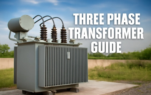
1000kVA Dry Type Transformer
NPC ELECTRIC 1000kVA Dry-Type Transformer offers efficient, oil-free power distribution with a compact design. Equipped with advanced insulation and cooling systems, it ensures safe and reliable operation with minimal maintenance. Ideal for industrial and commercial applications, it provides environmentally friendly and cost-effective performance. Standard features include three-phase configuration, primary voltages 208V–600V (e.g., 480V Delta, 600V Delta), secondary voltages such as 208Y/120V, 480Y/277V, or custom, aluminum or copper windings, 150°C rise (standard) or 115°C/80°C with 220°C insulation class, ±2×2.5% primary taps, NEMA 1 ventilated enclosure (NEMA 3R/encapsulated options), natural convection cooling (AN), electrostatic shielding, and NEMA-compliant low sound levels.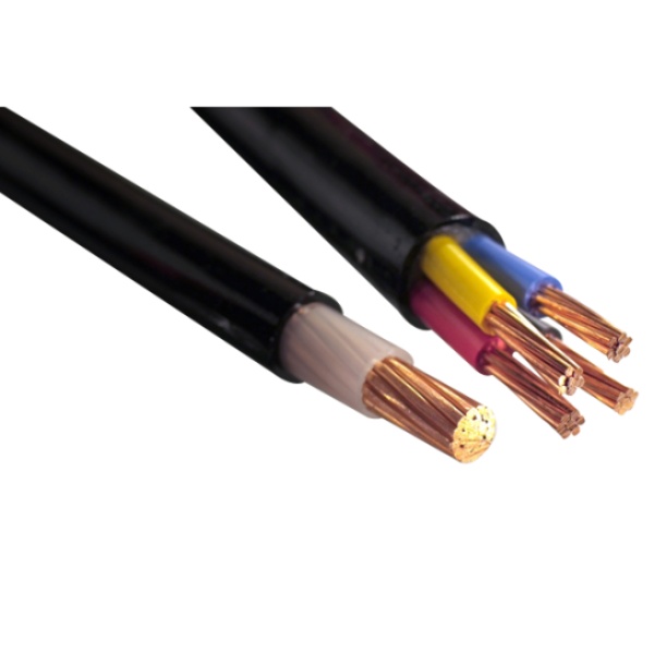
600/1000V XLPE Insulated Low Voltage Power Cable to IEC 60502-1 Standard
The 600/1000V XLPE Insulated Low Voltage Power Cable manufactured to IEC 60502-1 is engineered to provide dependable power transmission in demanding electrical installations. High-purity conductors combined with XLPE insulation deliver excellent electrical stability, high current capacity, and resistance to thermal aging. XLPE insulation allows higher operating temperatures and improved mechanical strength, ensuring long-term performance under continuous service conditions. Rated for 600/1000V systems, this cable supports safe and efficient power distribution in fixed installations. Compliance with IEC 60502-1 ensures the cable meets international standards for design, testing, and operational safety. Its robust construction makes it suitable for indoor, outdoor, and underground applications where durability and reliability are essential.
6300kVA Dry Type Transformer
The NPC ELECTRIC 6300kVA Dry Type Transformer is a high-performance, heavy-duty power solution designed for large industrial and commercial applications. With a capacity of 6300kVA, it features cutting-edge dry-type insulation technology, offering superior safety, low maintenance, and extended reliability. Built to withstand demanding operating conditions, this transformer provides stable, efficient, and noise-free performance while minimizing environmental impact. Its dry-type ventilated or encapsulated construction provides zero fluid maintenance, no spill/leak risks, and suitability for extreme high-density loads, space-limited, or environmentally restricted high-power applications.
333kVA Single Phase Pole Mounted Transformer
NPC ELECTRIC'S 333kVA single phase pole mounted transformer stands as a powerhouse solution for intensive overhead distribution requirements, effectively reducing primary voltages such as 12.47kV, 24.94kV, or 34.5kV to secondary voltages including 120/240V, 277V, or 347V. Crafted with premium grain-oriented silicon steel cores and durable windings, it delivers outstanding energy efficiency, low losses, and compliance with modern DOE efficiency regulations alongside IEEE C57 and ANSI standards. The tank incorporates corrugated fins for optimal natural oil circulation (ONAN), supporting a 65°C temperature rise and robust overload handling. Equipped with essential protections like pressure relief valves, high-voltage bushings, and surge arresters, this transformer ensures dependable operation in exposed conditions. Its design prioritizes quiet performance, minimal maintenance, and extended service life, making it highly suitable for utilities managing substantial single-phase loads in evolving power networks.
250kVA Oil Immersed Transformer
The 250kVA Oil Immersed Transformer produced by NPC ELECTRIC adopts a new insulation structure to improve the short-circuit resistance; the core adopts high-quality cold-rolled silicon steel sheets; the high-voltage winding adopts high-quality oxygen-free copper wire and adopts a multi-layer cylinder structure; all fasteners are specially treated to prevent loosening. Fully compliant with ANSI C57.12.00, IEEE C57.12.90, IEC 60076, DOE 2016 efficiency standards (and fully prepared for 2029 amendments with reduced losses), this 250 kVA unit delivers outstanding energy efficiency (>99.45% typical), low no-load and load losses, excellent thermal performance, and proven durability in demanding outdoor environments.
Instrumentation Cables—XLPE Insulated, Overall Screened ,Unarmoured PVC Sheathed Cables(CU/XLPE/OSCR/PVC)
Instrumentation cables come in twisted pairs, triads, and quads, depending on the customer’s applications; twisting reduces any electromagnetic interference by reducing the chances of electrical voltages and currents being induced in the conductor. Individual and overall screening are also applied in instrumentation cables to optimize the signal transferred and further reduce any electromagnetic interference. Screening of pairs, triads, or quads also includes a drain wire earthed to the ground, which ensures a noise-free signal transmission. Depending on the application, instrumentation cables can be insulated with PVC or XLPE; the cables can be armoured or unarmoured. The sheathing materials can be of PVC, LSZH, or PE. The cables can have additional flame retardant or flame retardant properties, and they can be manufactured with special protections such as lead sheaths, or DRYLAM or AIRBAG technology.
25kVA Single Phase Pad Mounted transformer
The 25kVA Single Phase Pad Mounted transformer with a power rating of 25 kVA, the high voltage of the transformer is 24940GRDY/14400×12470GRDY/7200V, which is a dual high voltage design. Customers can switch between 14.4kV and 7.2kV through a dual voltage switch according to the distribution line. There is a five-position voltage regulating switch on the high-voltage side, which can allow small changes in voltage within ±2 * 2 ½%. The 25 kVA transformer comes complete with an oil level indicator and a 4-position load break switch, adding to its versatility and ease of maintenance.
2000kVA Oil Immersed Transformer
The 2000kVA Oil Immersed Transformer is a high-capacity, three-phase, liquid-filled distribution transformer engineered for reliable outdoor pad-mounted or substation installations in utility networks, large commercial/industrial complexes, data centers, heavy manufacturing plants, and high-demand power distribution systems. Standard configuration includes mineral oil or FR3 natural ester fluid, ONAN cooling, aluminum or copper windings, high-voltage 34.5kV / 24.94kV / 13.8kV / 12.47kV / 4.16kV (delta or wye), low-voltage 480Y/277V, 208Y/120V, 600Y/347V or custom, ±2×2.5% HV taps, radial or loop-feed dead-front design, bayonet fuses + partial-range current-limiting fuses (optional), load-break switch.
Medium Voltage Unarmored Power Cable
The Medium Voltage Unarmored Power Cable is designed for efficient power transmission and distribution in utility, industrial, and commercial electrical networks. Manufactured with high-conductivity copper or aluminum conductors, advanced XLPE insulation, metallic screening, and a durable outer sheath, the cable delivers excellent electrical performance and long-term operational reliability. Designed for voltage ratings from 3.6/6kV up to 26/35kV, the cable provides superior dielectric strength, low insulation losses, and excellent thermal stability. The absence of armouring reduces cable weight and improves installation flexibility, making it particularly suitable for installations within cable trays, ducts, tunnels, and protected environments. The outer sheath provides reliable protection against moisture, chemicals, UV radiation, and environmental exposure. Manufactured according to IEC 60502-2 and international standards, the cable is widely used in substations, power plants, renewable energy facilities, industrial complexes, and utility distribution systems. The Medium Voltage Unarmored Power Cable offers a cost-effective, lightweight, and reliable solution for modern medium-voltage power transmission applications.Welcome your inquiry
Honesty, Integrity, Frugality, Activeness and Passion