How to Design a Single Phase Transformer: Complete Handbook with Formulas, Materials & Efficiency Optimization
2026-03-03
1. Single-Phase Transformer Design
Single-phase transformer design is a critical process in electrical engineering, involving the precise calculation and selection of core materials, windings, insulation, and parameters to achieve optimal performance, efficiency, and reliability. At its core, a single-phase transformer operates on electromagnetic induction principles, transferring electrical energy from a primary winding to a secondary winding via a shared magnetic core—typically constructed from high-grade silicon steel laminations (E-I or shell-type) to minimize eddy current and hysteresis losses.
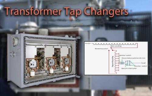
Key design steps include determining the rated kVA capacity, primary and secondary voltages (e.g., 120/240V common in residential applications), turns ratio (N_p/N_s = V_p/V_s), flux density (usually 1.0–1.5 Tesla), and current densities for copper or aluminum windings. Engineers optimize core cross-section for minimal no-load losses, calculate the window area for the conductor space factor (~0.5), and incorporate tap changers (±2×2.5%) for voltage regulation. Modern designs prioritize DOE 2016/202X efficiency compliance, low temperature rise (55–65°C), and options like oil-immersed (ONAN) or dry-type cooling for pole-mounted, pad-mounted, or distribution uses.
Advanced considerations encompass equivalent circuit modeling (with R1, X1, R0, X0 parameters), loss reduction techniques, overload capacity, and eco-friendly materials like FR3 fluid. Proper single-phase transformer design ensures high efficiency (>98% in premium models), cost-effectiveness, and compliance with ANSI/IEEE, IEC standards—essential for export markets in North America, Europe, Asia, and beyond.
For a professional single-phase transformer manufacturer, design is not merely about voltage conversion—it is an integrated process involving magnetic design, thermal management, material optimization, and compliance with international standards (IEC, IEEE, ANSI).
From an engineering standpoint, transformer design must balance:
- Electrical performance
- Mechanical integrity
- Thermal stability
- Material usage efficiency
- Long-term reliability
The core objective is safe and efficient energy transfer between primary and secondary windings while minimizing losses and maximizing service life.
2. Fundamental Principles and Magnetic Flux Theory
The operation of a transformer is based on Faraday’s Law:
E = 4.44fNΦmax
Where:
- E = RMS induced voltage
- f = frequency (Hz)
- N = number of turns
- Φmax = maximum magnetic flux (Wb)
Magnetic flux depends on:
Φ=B×A
Where:
- B = flux density (Tesla)
- A = cross-sectional area of the core (m²)
Proper control of flux density is critical. Excessive B leads to saturation and increased core losses, while too low B increases material cost due to oversized core dimensions.
Typical flux density values:
|
Core Material |
Recommended Flux Density (T) |
|
CRGO Silicon Steel |
1.5 – 1.7 |
|
Amorphous Core |
1.3 – 1.4 |
Maintaining optimized magnetic flux ensures stable voltage and improved material efficiency.
3. Core Design: Cross-sectional Area & Core Losses
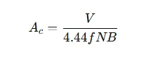
In single-phase transformer core design, the cross-sectional area (A) of the magnetic core is a fundamental parameter that directly influences flux density (B), core losses, and overall efficiency. The core—typically made of cold-rolled grain-oriented silicon steel laminations (E-I or shell type)—is sized using the equation:
A = (V × 10⁸) / (4.44 × f × N × B_max × K_f),
where V is RMS voltage, f is frequency (50/60 Hz), N is the number of turns, B_max is the maximum flux density (usually 1.0–1.5 T for optimal performance), and K_f is stacking factor (~0.95–0.97).
A larger cross-sectional area reduces B_max, lowering hysteresis and eddy current losses (core losses = hysteresis + eddy). Hysteresis loss scales with B_max^{1.6–2}, while eddy current loss is proportional to (B_max × f × t)^2, where t is lamination thickness (0.23–0.35 mm common in 2026 designs).
Modern designs target low no-load losses (<0.5–1 W/kg at 1.5 T) to meet DOE 2016/202X and IEC efficiency standards. Thinner laminations, high-permeability GO steel, and optimized B (around 1.3–1.4 T) minimize core losses while keeping material costs and transformer size balanced—critical for pole-mounted, pad-mounted, and distribution single-phase transformers in export markets.
The cross-sectional area of the magnetic core determines how much magnetic flux it can carry without saturation.
Approximate core area formula:
Design considerations:
- Core material (CRGO or amorphous)
- Lamination thickness (reduces eddy currents)
- Stacking factor (typically 0.9–0.95)
- Cooling method (air or oil)
Core Losses
Core losses consist of:
- Hysteresis loss
- Eddy current loss
They depend on frequency, flux density, and material quality. Modern transformer design emphasizes reducing core losses to improve efficiency, especially in long-term continuous operation.
4. Winding Design: Turns Ratio, Wire Sizes & Voltage Levels
In single-phase transformer winding design, the turns ratio (N_p: N_s) is the foundational parameter, directly determining voltage transformation per Faraday's law: V_s / V_p = N_s / N_p (or inversely for current: I_p / I_s = N_s / N_p). For common residential applications (e.g., 240V primary to 120/240V secondary split-phase), the ratio is typically 2:1 overall, with a center-tapped secondary for balanced 120V legs. Precise calculation starts from rated voltages, incorporating tap changers (±2×2.5% usually) for regulation under load variation.
Wire sizes are selected based on current density (typically 2–3 A/mm² for copper, or 1.5–2 A/mm² for aluminum) to limit I²R losses and temperature rise (≤65°C). Primary wire carries lower current (I_p = kVA / V_p), allowing thinner gauges; secondary handles higher current (I_s = kVA / V_s), requiring thicker wire (e.g., AWG #10–#2 for 15–50 kVA models). Space factor (~0.4–0.6) in the core window constrains total conductors.
Voltage levels dictate insulation class (e.g., 600V for LV, higher BIL for MV primaries like 12470V). Modern designs optimize for DOE 2016/202X efficiency, using enameled copper/aluminum, layer insulation, and interleaving to reduce leakage reactance. Proper winding ensures high efficiency (>98% possible), minimal hotspots, and compliance with ANSI/IEEE/IEC standards for pole-mounted or pad-mounted single-phase transformers in global export markets.
Turns Ratio
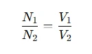
Where:
- N1, N2 = primary and secondary turns
- V1, V2 = primary voltage and secondary voltages
For example, in a single-phase 480 to 120/240 transformer wiring diagram, the ratio is:
480: 240= 2: 1
The secondary winding may include a center tap for a 120/240V split-phase supply.
Wire Sizes Selection
Conductor size depends on current density:
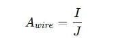
Typical current density:
|
Cooling Type |
Current Density (A/mm²) |
|
Oil-immersed |
2.5 – 3.5 |
|
Dry type |
2.0 – 3.0 |
Oversized conductors increase material usage; undersized conductors raise temperature and reduce life cycle.
5. Materials Selection and Material Efficiency
Key materials:
|
Component |
Typical Material |
Design Goal |
|
Core |
CRGO silicon steel |
Low hysteresis loss |
|
Conductor |
Copper / Aluminum |
High conductivity |
|
Insulation |
Kraft paper / Epoxy |
Thermal endurance |
|
Tank |
Mild steel |
Mechanical strength |
Is Copper Always Preferred?
Copper offers superior conductivity and better thermal performance, but aluminum reduces weight and cost. For export markets, decision-making often considers:
- Raw material cost volatility
- Environmental impact
- Recycling efficiency
- Transportation cost
Optimizing material reduces waste and improves competitiveness for a single-phase transformer manufacturer.
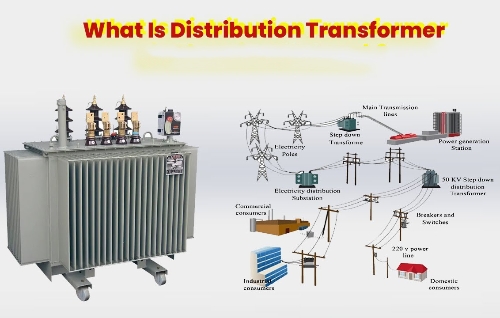
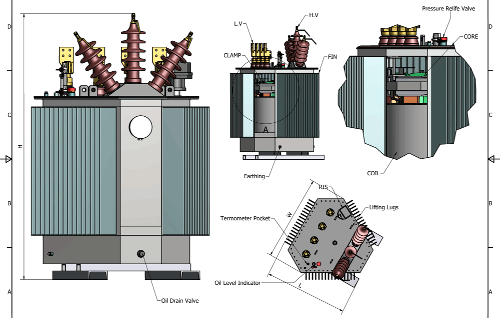
6. Transformer Diagrams and Wiring Configurations
Single-phase transformer diagrams and wiring configurations are essential for safe installation, correct voltage output, and compliance with electrical codes. The most common setup is the split-phase residential configuration: primary winding connected to single-phase high voltage (e.g., 7200V or 12470GrdY/7200), secondary with center-tapped winding providing 120/240V output—two 120V legs (L1-N and L2-N) and 240V across L1-L2 for appliances.
Key diagrams include:
- Schematic diagram: Shows primary and secondary windings, core, taps (±2×2.5%), and equivalent circuit (R1, X1, Rc, Xm).
- Connection diagram: Illustrates bushing terminals (H1/H2 primary, X1/X2/X3 secondary), with X2 as neutral/center tap grounded.
- CSP wiring: Built-in fuses, arresters, and breakers on primary/secondary sides for self-protection.
- Pole-mounted wiring: Primary bushings to overhead lines, secondary to service drop (triplex cable).
- Pad-mounted wiring: Dead-front or live-front elbows for underground cables, loop-feed or radial-feed options.
Proper grounding (neutral bonded at transformer or service entrance) prevents shock hazards. Diagrams often follow ANSI/IEEE C57.12.20 standards, with color-coded terminals (H1 black, X1/X3 red/black) for easy identification.
Understanding these configurations ensures correct phasing, balanced loads, and high efficiency in pole-mounted, pad-mounted, or distribution single-phase transformers—critical for North American, export, and global utility projects.
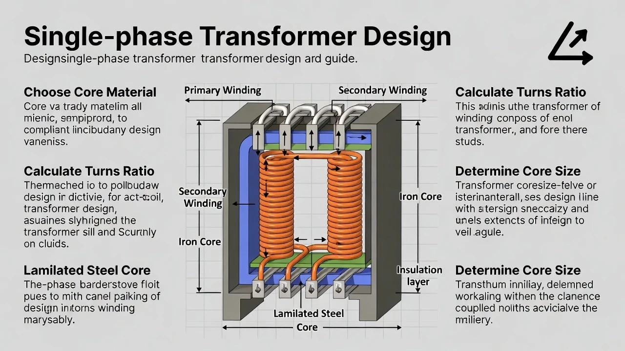
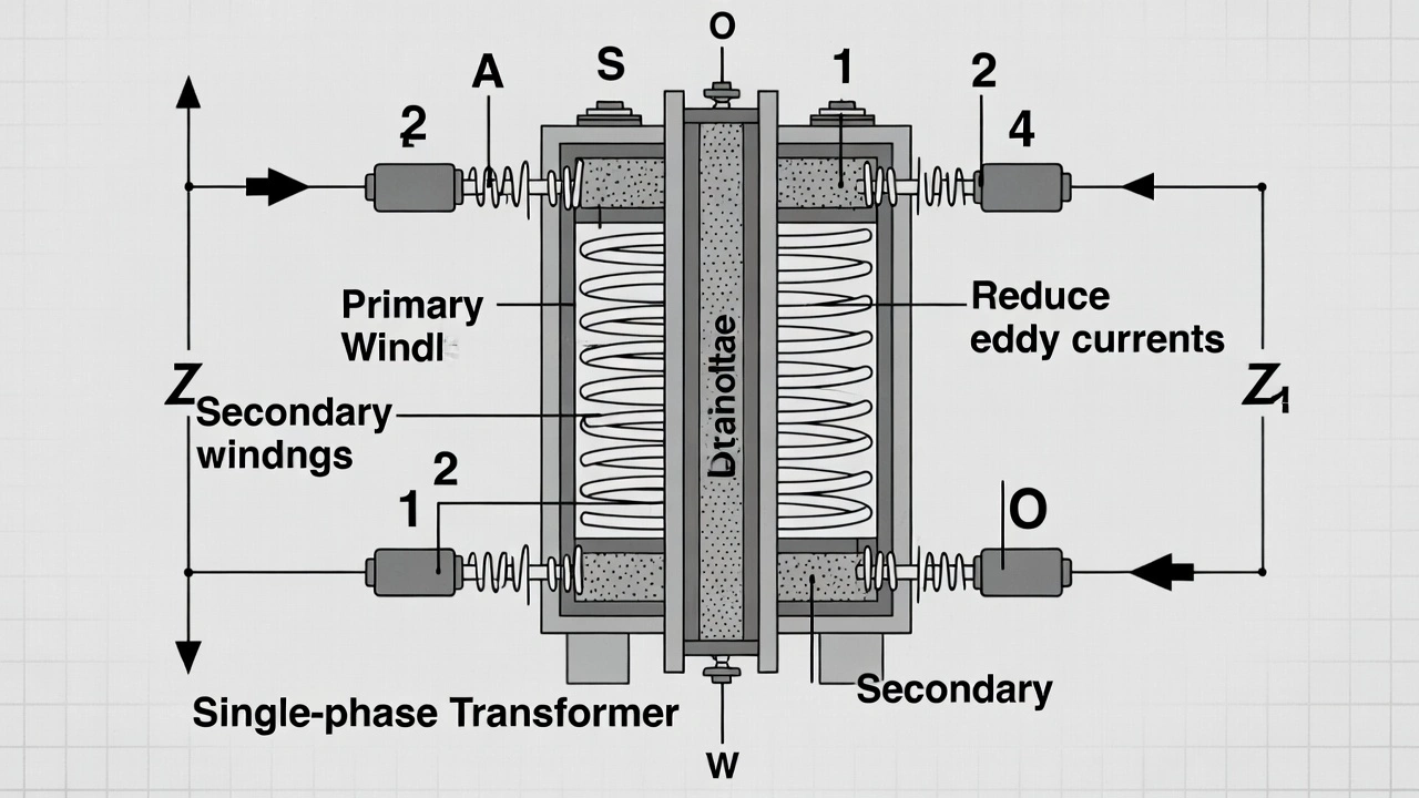
Single Phase Transformer Diagram
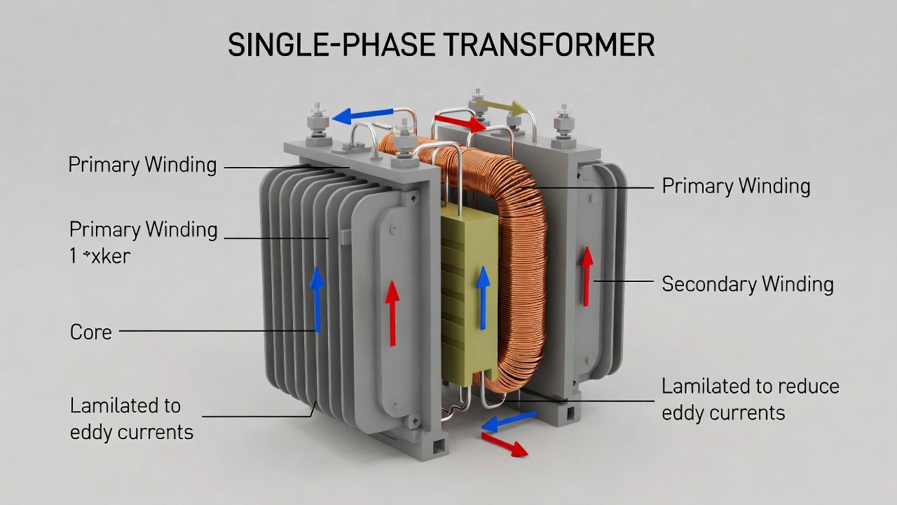
A standard single-phase transformer diagram includes:
- Laminated core
- Primary winding
- Secondary winding
- Insulation barriers
Wiring Configurations
-
Single-phase transformer wiring diagram
-
Single-phase 480 to 120/240 transformer wiring diagram
- Single-phase pole-mounted transformer wiring diagram
-
3-phase single-phase transformer
-
Single to three phase transformer
|
Application |
Voltage Example |
Installation Type |
|
Residential |
120/240V |
Pole mounted |
|
Industrial |
480/240V |
Floor mounted |
|
Rural grid |
11kV/230V |
Pole mounted |
|
Phase conversion |
240V → 3Φ |
Rotary/static system |
7. Losses, Efficiency Optimization & Thermal Design
Single-phase transformer losses consist of no-load losses (core losses: hysteresis + eddy current) and load losses (copper losses: I²R in windings). No-load losses dominate at low loads and are minimized by using high-permeability grain-oriented silicon steel, thinner laminations (0.23–0.27 mm), and optimized flux density (1.3–1.4 T). Load losses are reduced with low-resistance copper windings, larger conductor cross-sections, and aluminum alternatives where cost-effective.
Efficiency optimization targets >98% peak efficiency per DOE 2016/202X and IEC standards. Techniques include precise turn ratios, reduced leakage reactance via interleaving windings, low space factor losses, and eco-friendly insulating oils (FR3) for better heat transfer. Modern designs incorporate amorphous core materials for ultra-low no-load losses in premium models.
Thermal design ensures temperature rise stays within limits (55–65°C for oil-immersed, 80–100°C for dry-type). Key elements: adequate oil volume/convection in ONAN cooling, finned tanks or radiators for heat dissipation, hot-spot calculations (via thermal models), and overload capacity (e.g., 150% for short durations). Proper ventilation, thermal sensors, and derating for ambient temperatures (>40°C) prevent insulation aging and extend lifespan to 30+ years.
These optimizations deliver high efficiency, lower operational costs, and compliance for pole-mounted, pad-mounted single-phase transformers in global export markets.
Total transformer losses:
Ptotal=Pcore+Pcopper
Copper Loss
Pcu=I2R
Copper loss depends on resistance and load current.
Efficiency
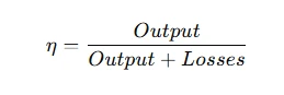
Modern designs target:
- ≥98% efficiency for distribution units
- Reduced no-load loss for long-term operation
Thermal Considerations
The temperature rise must comply with the insulation class:
|
Insulation Class |
Max Temperature (°C) |
|
A |
105 |
|
F |
155 |
|
H |
180 |
Efficient cooling improves life cycle performance and reduces environmental impact.
8. Manufacturing Process & Materials Flow
Professional transformer design integrates manufacturing feasibility.
Manufacturing Process
- Core cutting and stacking
- Coil winding
- Insulation assembly
- Core-coil assembly
- Vacuum drying
- Oil filling (if oil type)
- Testing
Materials Flow Optimization
- Reduce scrap during lamination cutting
- Optimize copper length calculation
- Automate coil winding
- Implement quality checkpoints
Effective materials and energy management enhances profitability and sustainability.
9. Life Cycle, Environmental Impact & Sustainability
Life cycle analysis considers:
- Raw material extraction
- Manufacturing energy consumption
- Operational losses
- End-of-life recycling
Environmental impact reduction strategies:
- Use amorphous cores to reduce core losses
- Improve material efficiency
- Minimize oil leakage risk
- Design for disassembly and recycling
A well-designed transformer can operate 25–35 years with proper maintenance.
10. Practical Engineering Checklist
Before finalizing transformer design:
- Verify primary voltage and secondary voltages
- Confirm the turns ratio calculation
- Check flux density within limits
- Validate wire sizes and temperature rise
- Optimize cross sectional area
- Evaluate core losses and copper losses
- Ensure compliance with IEC/IEEE standards
- Review mechanical stability
- Confirm efficiency at 50% and 100% load
- Evaluate export packaging requirements
Designing a single-phase transformer is a multidisciplinary engineering task combining electromagnetic theory, thermal analysis, materials science, and manufacturing optimization. A competitive single phase transformer manufacturer must integrate magnetic flux control, optimized material usage, precision winding design, and efficient production processes.
By balancing core losses, conductor sizing, insulation selection, and life cycle considerations, engineers can achieve superior efficiency, long-term reliability, and reduced environmental impact—meeting global market requirements and advancing modern power system performance.
Related Articles
Related Products
35kV 46kV Power Transformer
NPC ELECTRIC's 35kV and 46kV power(electrical) transformer complies with international standards such as IEC and ANSI, and features high efficiency, low loss, and strong insulation. This product is widely used in power grid main transformers, power plants, industrial and mining enterprises, and large infrastructure projects. Key features include mineral oil or FR3 natural ester insulation (ONAN/ONAF/ODAF cooling options), copper or aluminum windings, primary voltages 35kV or 46kV (grounded wye or delta, with dual-voltage configurations), secondary voltages 6.6kV, 11kV, 13.8kV, 33kV, or custom (e.g., 13.8kV/480V or 35kV/11kV), BIL ratings 200–650kV depending on voltage class, impedance typically 8–12%, ±2×2.5% or ±5% off-load tap changer (OLTC optional), conservator tank or sealed tank design, Buchholz relay, pressure relief device, oil temperature gauges, winding temperature indicators, and ANSI 61 gray or custom tank finish.2Y-high-voltage-power-cable-2.webp)
2XS(FL)2Y MDPE High Voltage 76/132 (145)kV Power Cable
The 2XS(FL)2Y MDPE High Voltage Power Cable is a single-core aluminum conductor cable with XLPE insulation and an MDPE sheath, rated 76/132 (145) kV. Designed for extra-high voltage power transmission, it meets IEC 60840 standards, offering excellent electrical performance, mechanical protection, and water resistance for demanding environments. Its construction includes a copper conductor, semi-conductive conductor screen, XLPE insulation, semi-conductive insulation screen, semi-conductive water swelling tape, copper wire metallic screen, longitudinal aluminum tape with PE copolymer coating, and an MDPE sheath. Water-blocking tape prevents water propagation, ensuring reliable operation in power stations, industrial plants, and distribution systems. Suitable for underground, underwater, outdoor, indoor, and duct installations, this cable is ideal for distribution networks and connections to generation units, industrial plants, and processes.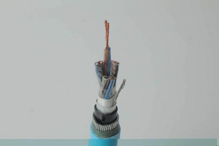
Instrumentation Cables—PVC Insulated, Overall Screened, Wire Armoured PVC Sheathed Cables(CU/PVC/OSCR/SWA/PVC)
Instrumentation Cables are multi-conductor cables that carry and transport low-voltage electrical signals. These low-voltage signals are used to control and monitor electrical power systems. Instrumentation cables have many different industrial applications that include broadcasting, equipment control, such as drilling and pumping in the oil and gas industry, and data transfer, which includes analog and digital signals. They are manufactured according to the BS EN 50288-7 and BS EN 50288-1 standards to ensure quality. Depending on the application, instrumentation cables can be insulated with PVC or XLPE; the cables can be armoured or unarmoured. The sheathing materials can be of PVC, LSZH, or PE. The cables can have additional flame retardant or flame retardant properties, and they can be manufactured with special protections such as lead sheaths, or DRYLAM or AIRBAG technology.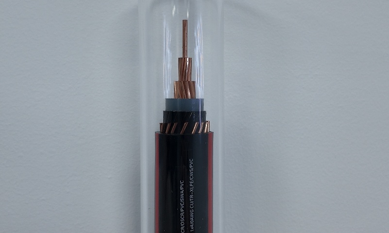
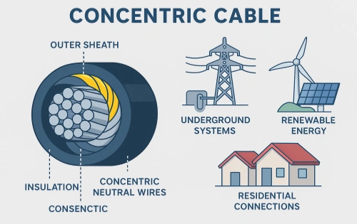
Quadruplex URD Cable
The Quadruplex URD Cable is a robust 600V underground residential distribution cable designed for efficient service entrance and secondary power delivery. It consists of four insulated AA8000 aluminum alloy phase conductors and a concentric neutral, all protected by a tough black polyethylene sheath. The quadruplex configuration provides a compact yet high-capacity solution for direct burial applications, offering excellent electrical balance and mechanical strength. Manufactured with XLPE insulation, this cable delivers superior electrical properties, moisture resistance, and long-term durability. Lightweight and cost-effective compared to copper alternatives, the Quadruplex URD Cable meets UL 854, ICEA, and ASTM standards. It undergoes rigorous quality testing from raw materials to finished product, ensuring consistent performance in demanding underground environments.
Instrumentation Cables—XLPE Insulated, Overall Screened ,Unarmoured PVC Sheathed Cables(CU/XLPE/OSCR/PVC)
Instrumentation cables come in twisted pairs, triads, and quads, depending on the customer’s applications; twisting reduces any electromagnetic interference by reducing the chances of electrical voltages and currents being induced in the conductor. Individual and overall screening are also applied in instrumentation cables to optimize the signal transferred and further reduce any electromagnetic interference. Screening of pairs, triads, or quads also includes a drain wire earthed to the ground, which ensures a noise-free signal transmission. Depending on the application, instrumentation cables can be insulated with PVC or XLPE; the cables can be armoured or unarmoured. The sheathing materials can be of PVC, LSZH, or PE. The cables can have additional flame retardant or flame retardant properties, and they can be manufactured with special protections such as lead sheaths, or DRYLAM or AIRBAG technology.
NAYY-J/NAYY-O Cables
The NAYY-J/NAYY-O Solar Cables provide cost-effective, reliable power distribution in photovoltaic systems. With sector-shaped or round aluminum conductors, PVC core insulation, and robust PVC outer jacket, they meet VDE 0276 requirements. NAYY-J includes a protective earth conductor, while NAYY-O is without. These cables excel in wet environments with superior water and chemical resistance, suitable for direct burial without additional protection. UV-stabilized and mechanically strong, they withstand soil stress and installation pulling forces. Low-weight aluminum reduces handling efforts, making them popular for extensive solar parks. NAYY-J/NAYY-O Solar Cables ensure efficient energy transfer with minimal losses, supporting sustainable solar infrastructure worldwide.
5000kVA Three Phase Pad Mounted Transformer
NPC ELECTRIC's 5000kVA Three Phase Pad Mounted Transformer (5 MVA) is a robust, liquid-immersed compartmental distribution transformer built for high-capacity outdoor pad-mounted installations on concrete foundations. Compliant with updated DOE energy conservation standards (post-2024 amendments, targeting high efficiency levels around 99.68% for 5000 kVA units), ANSI/IEEE C57.12.00, C57.12.34, C57.12.90, and related CSA/IEC norms, this transformer delivers top-tier energy efficiency, minimal no-load and load losses, and exceptional reliability in utility-scale, industrial, and commercial power systems. The tamper-resistant, weatherproof steel enclosure (dead-front or live-front) with NEMA 3R-equivalent protection ensures safety, reduced maintenance, and seamless blending into urban, suburban, or remote environments.
XLPE-HDPE Tree Cable Aluminum 25kV 1x50m㎡
The XLPE-HDPE Tree Cable Aluminum 25kV 1x50mm² is engineered for superior performance in medium-voltage overhead distribution networks, delivering exceptional reliability and long-term durability. Designed for challenging environments such as forested regions and urban areas, this cable ensures consistent power supply while minimizing maintenance and unplanned outages. Constructed with high-conductivity aluminum alloy 1350 wires, the cable features a round compacted conductor with class 2 stranding, achieving a minimum conductivity of 61% IACS and tensile strength of at least 130 MPa. Optional conductor shielding with an extruded semiconductor thermosetting compound is available for enhanced performance in 15kV and 25kV applications. The inner insulation is made from cross-linked polyethylene (XLPE), supporting continuous conductor operation at 90°C, and meeting ICEA S-121-733 physical standards. The robust outer cover is composed of high-density polyethylene (HDPE), offering outstanding resistance against weathering, UV radiation, mechanical abrasion, and electrical sparking up to 2.75kV. Standard cables come in gray with sequential metering markings in accordance with ASTM B230, while blue cables are recommended for harsher conditions requiring spark resistance above 5kV.
33kV 600A Neutral Zig-zag Grounding Reactor Transformer
The 33kV 600A Neutral Zig-zag Grounding Reactor Transformer is a high-performance grounding solution designed to meet the strict requirements of IEC 60076-1, IEC 60076-5, IEC 60076-20, and GB/T 1094.6 standards, with oil quality tested according to ASTM D6871. This grounding transformer is engineered to provide effective neutral grounding, enhanced system stability, and fault current limitation in medium- and high-voltage networks. With a primary voltage of 33kV and 11432.0kVA rating, the transformer supports 100A power rating for 10 seconds, making it ideal for system grounding applications in substations, industrial facilities, and renewable energy projects. The ONAN cooling method provides efficient heat dissipation for continuous operation, while the use of high-grade mineral insulating oil ensures long-term performance and compliance with international safety standards.
Instrumentation Cables—PVC Insulated, Overall Screened, Unarmoured PVC Sheathed Cables (CU/PVC/OSCR/PVC)
Instrumentation Cables CU/PVC/OSCR/PVC are PVC Insulated, Overall Screened, Unarmoured PVC Sheathed Cables. They are multi-conductor cables that carry and transport low-voltage electrical signals. These low-voltage signals are used to control and monitor electrical power systems. Instrumentation cables have many different industrial applications that include broadcasting, equipment control, such as drilling and pumping in the oil and gas industry, and data transfer, which includes analog and digital signals. They are manufactured according to the BS EN 50288-7 and BS EN 50288-1 standards to ensure quality. Depending on the application, instrumentation cables can be insulated with PVC or XLPE; the cables can be armoured or unarmoured. The sheathing materials can be of PVC, LSZH, or PE. The cables can have additional flame retardant or flame retardant properties, and they can be manufactured with special protections such as lead sheaths, or DRYLAM or AIRBAG technology.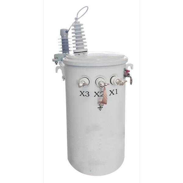
5kVA Completely self-protected(CSP) Single Phase Pole Mounted Transformer
NPC ELECTRIC the production of the 5kVA Completely self-protected(CSP) Single Phase pole Mounted transformer is designed for reliable and efficient distribution of electrical power in residential and light commercial applications. Built to withstand harsh outdoor conditions, this transformer is equipped with a self-protection system that eliminates the need for external protection devices, offering enhanced safety and durability. The CSP feature ensures that the transformer can handle internal faults such as short circuits or overloads without causing damage to the system. This compact, oil-immersed transformer is easy to install on poles, making it ideal for overhead distribution in areas with limited space. It is designed to meet international standards, including ANSI, IEEE, and CSA, ensuring high-quality performance and long-lasting operation. The 5kVA CSP transformer is energy-efficient, providing stable voltage regulation and minimizing maintenance requirements, making it an excellent choice for both utility and commercial applications.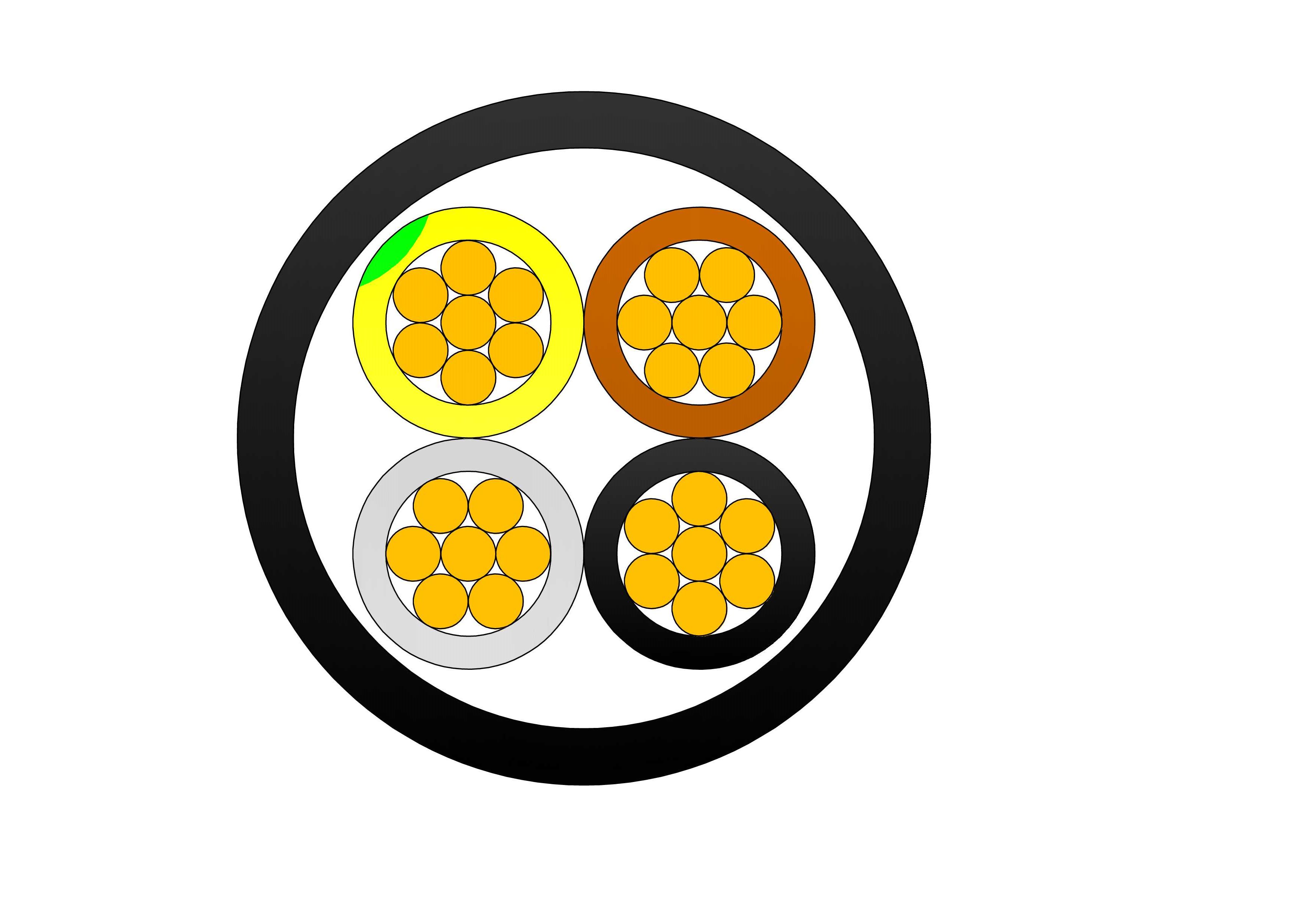
Single Core SWA Armoured Cable XLPE Insulated Power Cable
The Single Core SWA Armoured Cable is designed for reliable power transmission in installations requiring high mechanical protection and long-term durability. Manufactured with high-conductivity copper or aluminum conductors, premium XLPE insulation, galvanized steel wire armour, and a robust PVC outer sheath, the cable provides excellent electrical performance and superior mechanical strength. The XLPE insulation offers outstanding dielectric properties, low power losses, and thermal stability, allowing continuous conductor operation at temperatures up to 90°C. The galvanized steel wire armour enhances tensile strength and resistance to impact, compression, and external mechanical damage, making the cable ideal for underground and direct burial applications. The durable PVC sheath protects against moisture, chemicals, abrasion, UV exposure, and environmental conditions. Manufactured according to IEC 60502 standards, the cable is widely used in utility substations, renewable energy projects, industrial plants, commercial facilities, and power distribution networks. The Single Core SWA Armoured Cable combines electrical efficiency, safety, and mechanical reliability, making it a preferred solution for demanding power infrastructure projects worldwide.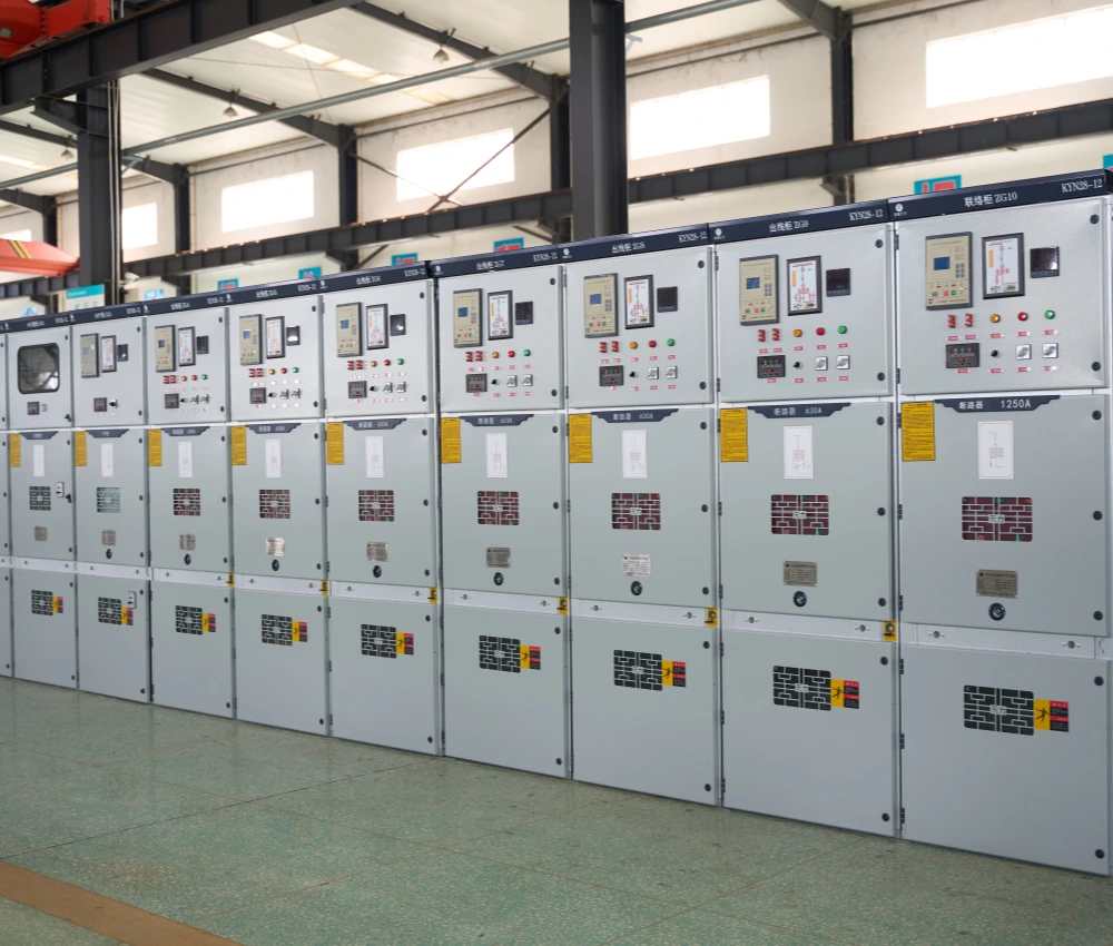
High Voltage Solid State Soft Start Cabinet
The High Voltage Solid State Soft Start Cabinet is an advanced motor control and protection system specifically engineered for medium and high-voltage industrial motors operating in demanding applications such as mining, petrochemical processing, power generation, water treatment, metallurgy, cement production, and large-scale manufacturing facilities. The cabinet utilizes high-performance thyristor solid-state control technology to provide smooth motor acceleration, reduce inrush current, minimize mechanical stress, and improve overall power system stability during motor startup operations. Designed with intelligent digital control architecture and precision-engineered power modules, the high voltage soft start cabinet significantly reduces voltage fluctuations, mechanical shock, and thermal stress commonly associated with direct-on-line motor starting methods. The system effectively extends motor service life, reduces maintenance requirements, and improves operational reliability for high-capacity pumps, compressors, conveyors, crushers, fans, and industrial processing equipment. Its modular cabinet structure simplifies installation, maintenance access, and future system expansion while ensuring safe and stable long-term operation. The High Voltage Solid State Soft Start Cabinet supports intelligent monitoring systems, programmable control logic, remote communication interfaces, and comprehensive protection functions for modern industrial automation environments.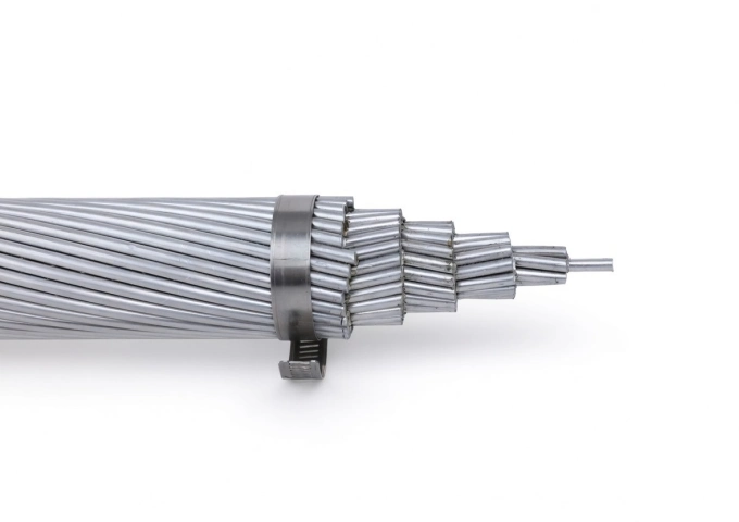
477 MCM Syringa AAC Cable
The 477 MCM Syringa AAC Cable is a high-performance All Aluminum Conductor designed for demanding overhead power transmission and distribution lines. Manufactured with 37 strands of premium 1350-H19 aluminum wire in a concentric lay configuration, this bare conductor provides excellent electrical conductivity with a low DC resistance of 0.0362 ohms per 1000 ft at 20°C. Featuring an overall diameter of 0.795 inches and a rated breaking strength of 8,690 lbs, the Syringa AAC delivers a robust ampacity of 639 amps while weighing only 447.8 lbs per 1000 ft. Its optimized strength-to-weight ratio minimizes sag and structural loading. Fully compliant with ASTM B-230 and B-231 standards, the 477 MCM Syringa AAC Cable offers outstanding corrosion resistance for long-term durability in harsh outdoor environments, making it the preferred choice for utility networks requiring cost-effective, high-reliability bare aluminum conductors.
USEB-90 AA8000 Concentric Underground Service Cable 600/1000V
The USEB-90 Underground Concentric Service Cable is an advanced low-voltage cable engineered for underground service entrance and secondary distribution systems. It utilizes compact AA8000 aluminum alloy phase conductors with XLPE insulation and a concentrically arranged neutral layer, protected by a durable polyethylene sheath. This design offers superior flexibility, high current-carrying capacity, excellent mechanical protection, and outstanding resistance to moisture and corrosion. Suitable for direct burial without additional conduit, the USEB-90 Underground Concentric Service Cable simplifies installation while ensuring long-term reliability. It meets international performance requirements and undergoes extensive quality testing to deliver consistent electrical performance and durability in demanding underground environments.Welcome your inquiry
Honesty, Integrity, Frugality, Activeness and Passion