Electric Transformer Working Principle: How Power Transformers Step Up & Down Voltage
2026-04-09
Electric Transformers in Modern Power Systems
Electric transformers form the backbone of global electrical infrastructure, silently enabling the efficient transmission and distribution of electrical energy across vast distances. An electric transformer, also known as an electrical transformer or power transformer, is a static device that transfers electrical energy between circuits through electromagnetic induction while changing voltage levels without altering frequency. In practical engineering contexts, these devices ensure that high-voltage power generated at plants can travel efficiently over long lines before being safely reduced for end-use in homes, industries, and commercial facilities.
From an actual working perspective, transformers operate continuously under varying loads, environmental conditions, and grid demands. Engineers in the field must consider not only ideal theoretical behavior but also real-world factors like heat dissipation, insulation integrity, and load fluctuations. As of 2026, advancements in materials and digital integration have pushed transformer efficiency closer to 99.7% in high-end models, supporting renewable energy integration and smart grid modernization. This article explores the science behind their operation, practical design considerations, and field applications with a focus on rigorous engineering analysis.
Fundamental Principle: Electromagnetic Induction and Faraday’s Law
At the core of every electric transformer lies Faraday’s Law of Electromagnetic Induction. When an alternating current (AC) flows through the primary winding, it generates a changing magnetic flux in the iron or steel core. This time-varying flux links with the secondary winding via mutual induction, inducing an electromotive force (EMF) according to the equation:
e = -N × (dΦ/dt)
where e is the induced EMF, N is the number of turns, and dΦ/dt is the rate of change of magnetic flux.
In real-world operation, the laminated core minimizes eddy current losses by reducing the path for circulating currents, while high-permeability materials like cold-rolled grain-oriented (CRGO) steel concentrate the flux efficiently. From a field engineer’s viewpoint, imperfect coupling (leakage flux) always exists, leading to slight voltage drops under load. This is quantified by the transformer’s voltage regulation, a critical parameter monitored during commissioning and routine maintenance.
The primary and secondary windings are electrically isolated but magnetically coupled. No direct electrical connection means transformers provide galvanic isolation, enhancing safety in electrical substation transformers and distribution networks. In practice, engineers calculate the turns ratio (N₂/N₁) to determine voltage transformation: V₂/V₁ ≈ N₂/N₁. A ratio greater than 1 yields a step-up transformer; less than 1 produces a step-down transformer.
Step-Up and Step-Down Mechanisms: Voltage Transformation in Detail
Step-up transformers increase voltage while decreasing current, crucial for long-distance transmission to minimize I²R losses. In power plants, generation voltage (typically 11–25 kV) is stepped up to 110 kV, 220 kV, or higher. The secondary winding has more turns than the primary, resulting in higher output voltage. From an operational standpoint, engineers must design windings with adequate insulation to withstand elevated electric stress and ensure cooling systems handle the thermal profile under full load.
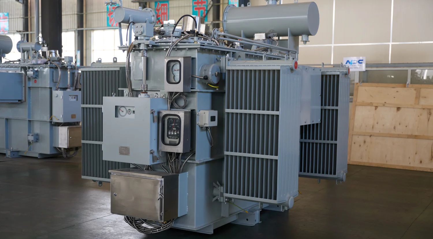
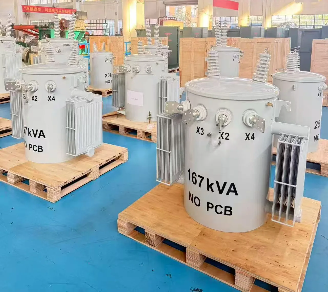
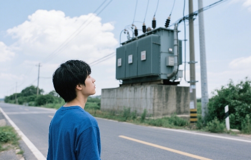
Conversely, step-down transformers reduce voltage for safe distribution and consumption. A classic example is the distribution transformer, which takes medium voltage (e.g., 11 kV or 33 kV) and outputs low voltage (400/230 V). Here, the primary winding has more turns, and the secondary has fewer. In field applications, such as electrical pole transformers mounted on utility poles, these units serve residential and small commercial loads directly. The electric transformer box housing protects windings and core while allowing natural or forced cooling.
The power balance (ignoring losses) remains P₁ ≈ P₂, so voltage reduction leads to current increase in the secondary. This demands thicker conductors in secondary windings for step-down transformers' voltage handling. Practically, engineers account for copper losses (I²R) and core losses (hysteresis + eddy currents) when specifying units for specific duty cycles. In 2026 designs, amorphous metal cores further reduce no-load losses, improving efficiency in lightly loaded distribution systems.
Table 1: Common Types of Electric Transformers and Their Voltage Transformation Roles
Caption: Types of Electric Transformers – Step-Up, Step-Down, and Distribution Applications in Real-World Power Systems
|
Transformer Type |
Primary Function |
Typical Voltage Transformation |
Common Applications |
Key Features in 2026 Designs |
|
Step-Up Transformer |
Increases voltage, reduces current |
Generation (11–25 kV) → Transmission (110–500+ kV) |
Power plants feeding high-voltage lines |
High insulation strength, low leakage flux |
|
Step-Down Transformer |
Decreases voltage, increases current |
Transmission (110–220 kV) → Distribution (11–33 kV) or final use (400/230 V) |
Substations and end-user supply |
Precise voltage regulation, robust secondary windings |
|
Final voltage reduction for consumers |
Medium voltage (11/33 kV) → Low voltage (400/230 V) |
Electrical pole transformer, pad-mounted electric transformer box |
Compact design, high reliability under variable loads |
|
|
Power Transformer (Substation) |
Bulk power transfer with voltage change |
High voltage levels in substations |
Electrical substation transformer in transmission networks |
On-load tap changers (OLTC), smart monitoring |
Construction and Types of Transformers from a Practical Engineering Lens
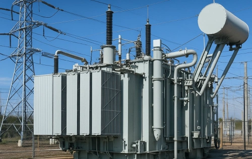
Modern power transformers feature a laminated core, primary and secondary windings, insulating materials, and a cooling system. In substations, large electrical substation transformers often use oil-immersed designs for superior dielectric strength and heat dissipation. Oil acts as both insulator and coolant, circulated naturally (ONAN) or forced (OFAF) in high-capacity units.
Distribution transformer types vary by installation:
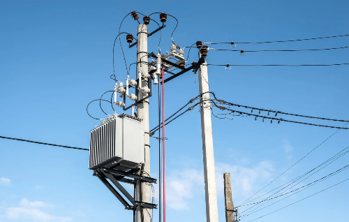
- Pole-mounted transformers (electrical pole transformer) are compact, oil-filled or dry-type units serving overhead lines in rural or suburban areas.
- Pad-mounted or electric transformer box styles suit urban underground distribution for aesthetics and safety.
- Dry-type transformers use cast resin or air cooling, preferred in fire-sensitive indoor environments like hospitals or data centers.
From actual working angles, selection depends on load profile, ambient temperature, and environmental regulations. Oil-filled units excel in outdoor high-power scenarios due to better thermal capacity, while dry-type offer lower maintenance and no spill risk. In 2026, hybrid designs and biodegradable ester fluids address sustainability demands in international projects.
Engineers rigorously calculate impedance, vector group (e.g., Dyn11 for distribution), and short-circuit withstand capability during design to ensure reliability under fault conditions.
Table 2: Comparison of Dry-Type vs Oil-Filled Electric Transformers
Caption: Dry-Type vs Oil-Filled Transformers – Key Differences in Construction, Cooling, and Application (2026 Practical Guide)
|
Parameter |
Dry-Type Transformer |
Oil-Filled Transformer (Liquid-Immersed) |
|
Cooling & Insulation Medium |
Air or solid epoxy/cast resin |
Mineral oil or eco-friendly ester fluid |
|
Typical Installation |
Indoor (data centers, hospitals, buildings) |
Outdoor (substations, pole-mounted, industrial) |
|
Fire Safety |
Excellent – no flammable liquid |
Moderate – requires containment and fire barriers |
|
Maintenance |
Low (no oil testing needed) |
Higher (regular oil analysis and filtration) |
|
Efficiency |
Good (slightly lower at high loads) |
Higher overall, especially in large capacities |
|
Voltage & Capacity Range |
Best for low to medium voltage |
Excellent for high voltage and high kVA ratings |
|
Environmental Impact |
Lower spill risk, easier disposal |
Potential oil leak risk (mitigated with modern fluids) |
|
Common Applications |
Electric transformer box in urban areas |
Electrical substation transformer, electrical pole transformer |
Real-World Operation in Power Distribution and Substations
In daily electrical engineering practice, transformers operate within complex grids. At generation, step-up units feed high-voltage transmission lines. Electrical substation transformers then step down to medium voltage for primary distribution. Finally, distribution transformers deliver usable voltage to consumers.
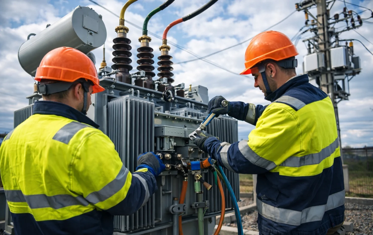
Consider a typical secondary transformer operating scenario: A 500 kVA pole-mounted unit on an 11 kV line supplies a neighborhood. Under peak load, voltage regulation must stay within ±5% to prevent equipment damage. Field teams monitor oil temperature, dissolved gas analysis (DGA), and winding resistance to predict issues like insulation degradation or hotspots.
Transformers' electrical engineering emphasizes parallel operation principles—matching voltage ratios, impedance, and polarity—to share loads without circulating currents. In renewable-heavy grids of 2026, transformers handle variable inputs from solar and wind, requiring enhanced tap changers (OLTC) for dynamic voltage control.
Efficiency, Losses, and Modern Design Innovations in 2026
Efficiency is paramount in practical deployments. Total losses include no-load (core) and load (copper) components. Modern designs optimize with:
- Low-loss cores and high-conductivity windings
- Advanced insulation systems
- Integrated cooling enhancements
In 2026, smart transformers incorporate IoT sensors for real-time monitoring of temperature, vibration, partial discharge, and oil condition. Predictive maintenance algorithms analyze data to forecast failures, reducing unplanned outages in critical infrastructure. Digital twins and SCADA integration allow remote diagnostics, especially valuable for international export projects spanning diverse climates.
High-efficiency models now achieve near 99.7% performance through improved geometries and materials, directly lowering operational costs and supporting global decarbonization goals. Engineers in the field perform regular thermographic scans and power factor tests to verify ongoing performance.
Table 3: Transformer Losses – Core Loss vs Copper Loss in Power Transformers
Caption: Table 2: Core (No-Load) Losses vs Copper (Load) Losses in Electric Transformers – Impact on Efficiency and Operation
|
Loss Type |
Description |
Dependency on Load |
Typical Contribution to Total Losses |
Practical Field Impact |
|
Core Loss (Iron Loss) |
Hysteresis + Eddy currents in the magnetic core |
Independent (constant even at no load) |
20–40% (higher at light load) |
Affects continuous energy waste in the distribution transformer |
|
Copper Loss (Load Loss) |
I²R losses in primary and secondary windings |
Varies with the square of current (I²) |
60–80% (dominant at full load) |
Increases significantly under heavy load in step-down transformers |
|
Total Losses |
Core Loss + Copper Loss |
Varies |
Determines overall efficiency |
Directly influences electricity bills and heat generation |
Example Efficiency Insight (2026): Modern high-efficiency power transformers achieve 98.5–99.7% efficiency by minimizing both losses through advanced CRGO/amorphous cores and optimized windings.
Safety, Maintenance, and Best Practices from Field Experience
Working with electric transformers demands strict adherence to safety protocols. High voltages pose arc-flash and shock risks; proper lockout/tagout, PPE, and clearance distances are non-negotiable. In substations, grounding and surge protection safeguard against transients.
Maintenance from a real operational viewpoint includes:
- Visual inspections for leaks, corrosion, and bushing cracks
- Oil sampling and DGA for internal fault detection
- Infrared thermography for hotspot identification
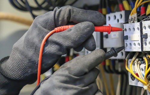
- Periodic electrical testing (insulation resistance, turns ratio)
Dry-type units require less fluid-related care but still need cleaning and connection torque checks. Proactive programs extend lifespan beyond 30–40 years while minimizing downtime and environmental impact. International standards (IEC, IEEE, ANSI) guide these practices for consistent quality in exported equipment.
Future Outlook: Smart and Sustainable Transformers
As grids evolve toward decentralization and renewables, electric transformer technology advances with AI-driven controls, solid-state options in niche applications, and eco-friendly materials. In 2026 and beyond, expect greater integration of sensors enabling self-regulating “smart” units that optimize voltage in real time, enhance grid stability, and support electric vehicle charging infrastructure.
For exporters and engineers specifying transformers for global markets, prioritizing modular designs, compliance with multiple standards, and embedded intelligence ensures competitiveness and long-term reliability.
In conclusion, understanding the working principle of electric transformers—rooted in electromagnetic induction and governed by turns ratio—provides the foundation for effective deployment. From high-voltage step-up at generation to low-voltage step-down at consumption, these devices enable safe, efficient electrical energy delivery. Practical field knowledge combined with 2026 innovations in monitoring and efficiency ensures power transformers continue powering modern civilization reliably.
Related Articles

Related Products
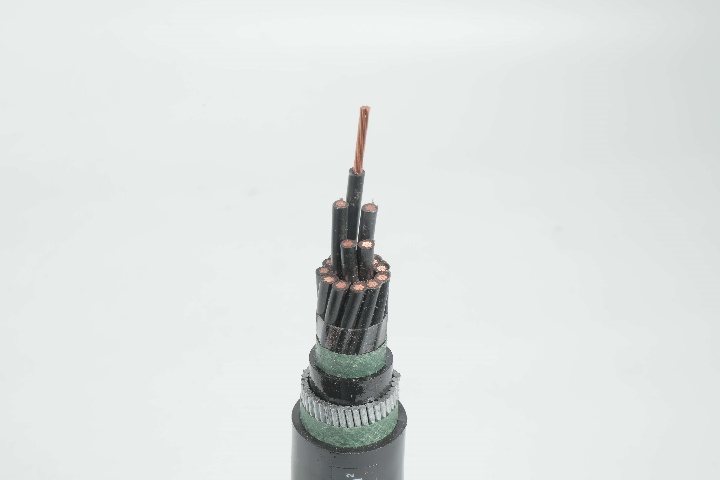
Control Cable 0.6/1 kV CVV-SWA to IEC 60502 Standard (2-16 core)
NPC Electric Control Cable 0.6/1 kV CVV-SWA to IEC 60502 Standard (2-16 core) is built for maximum protection in demanding control applications. It features concentric stranded copper conductors for excellent conductivity and flexibility, insulated with high-grade black PVC and identified by white numbers. A copper tape shield minimizes electromagnetic interference, while the steel wire armour (SWA) provides superior mechanical protection against impacts, rodents, and crushing. Dual PVC sheaths enhance flame retardancy and resistance to moisture and chemicals. Rated for voltages up to 1 kV, it operates reliably from -15°C to 70°C. Compliant with IEC 60502, this cable is suited for supervisory circuits, power stations, and installations in ducts, trays, underground, or direct burial. With 2 to 16 cores, it handles complex control setups, ensuring signal integrity and reducing downtime. Ideal for industrial environments requiring robust defence, the CVV-SWA delivers long-term durability, cost efficiency, and safety through advanced engineering and quality materials.
1500kVA Three Phase Pad Mounted Transformer
NPC ELECTRIC's 1500kVA Three Phase Pad Mounted transformer is designed with high-quality silicon steel sheets and insulating oil, in compliance with international standards such as IEC and ANSI, ensuring efficient and stable operation. It is suitable for a variety of scenarios such as urban power distribution, residential areas, commercial parks and industrial facilities. Whether it is ring network power supply or radial power supply, it can be flexibly applied to help achieve efficient and intelligent power transmission and distribution solutions.
Duplex Overhead Service Drop Cable
Duplex Overhead Service Drop Cable is a reliable aerial cable for secondary power distribution from utility poles to service entrances. Available with aluminum or copper conductors (phase and neutral, stranded) insulated with XLPE or PE and assembled in duplex configuration, it offers excellent mechanical strength and weather resistance. Compliant with ASTM B-230, B-231, ICEA S-76-474, and ANSI/ICEA standards, this cable supports 600V applications with superior UV, moisture, and abrasion protection. The self-supporting design ensures reduced sag and easy installation over medium spans. The Duplex Overhead Service Drop Cable delivers low power losses, high current capacity, and long service life in harsh outdoor conditions. Lightweight and flexible, it is widely used for single-phase service drops in residential, commercial, and rural electrification projects requiring safe, cost-effective overhead connections worldwide.
Single Core Aluminum Cable AL/XLPE/PVC Low Voltage Power Cable
The Single Core Aluminum Cable AL/XLPE/PVC is a high-performance low-voltage power cable designed for efficient electrical power transmission and distribution. Manufactured with a high-conductivity aluminum conductor, premium XLPE insulation, and a durable PVC outer sheath, the cable provides an economical and lightweight alternative to copper cables while maintaining excellent electrical performance. The XLPE insulation offers superior dielectric strength, low insulation loss, and excellent thermal stability, allowing continuous conductor operation at temperatures up to 90°C. The PVC sheath protects the cable from moisture, abrasion, chemicals, UV exposure, and mechanical damage, ensuring reliable performance in various installation environments. Its lightweight aluminum conductor reduces installation costs and simplifies handling during construction projects. Manufactured according to IEC 60502-1 and other international standards, the cable is suitable for power stations, industrial facilities, commercial buildings, renewable energy systems, and utility distribution networks. The Single Core Aluminum Cable AL/XLPE/PVC combines cost efficiency, reliability, durability, and safety, making it an ideal choice for modern electrical infrastructure projects worldwide.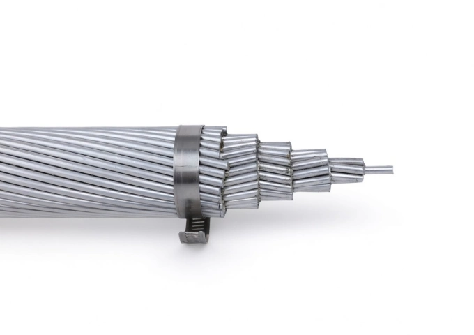
2000 MCM Cowslip AAC All Aluminum Bare Conductor Cable
The 2000 MCM Cowslip AAC Cable represents premium All Aluminum Conductor technology for overhead power applications. Built with 91 strands of high-conductivity 1350-H19 aluminum, this bare conductor delivers an optimal balance of electrical efficiency and mechanical robustness. With a 1.631-inch diameter, 32,200 lbs breaking strength, and 1518 amps ampacity, the Cowslip AAC offers low DC resistance of 0.00864 ohms per 1000 ft at 20°C and a weight of 1877 lbs per 1000 ft. This design minimizes sag while providing excellent corrosion resistance for extended outdoor service. Manufactured to meet ASTM B-230 and B-231 standards, the 2000 MCM Cowslip AAC Cable undergoes extensive quality testing from raw materials through finished product. It is the ideal solution for new installations and upgrades in transmission and distribution systems that demand lightweight, high-conductivity bare aluminum conductors.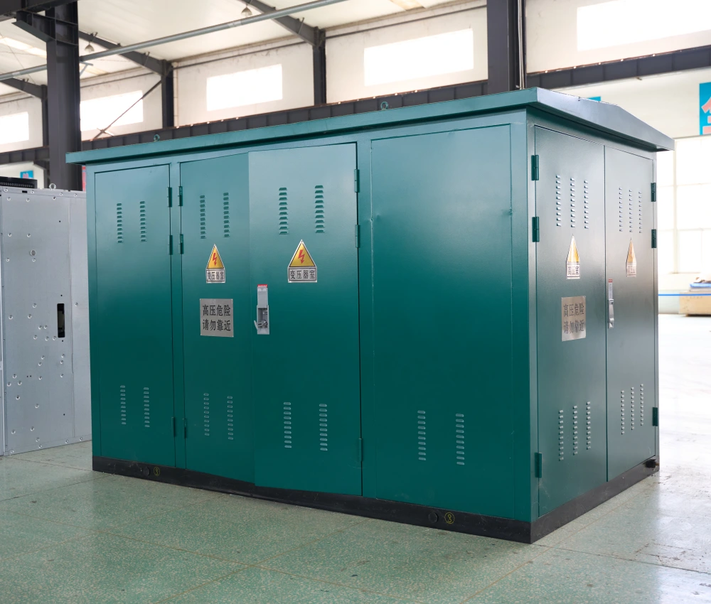
High Voltage Prefabricated Transformer Substation
The High Voltage Prefabricated Transformer Substation is a fully integrated power distribution system designed for high-voltage transmission and medium-voltage distribution applications in utility networks, renewable energy facilities, industrial plants, and infrastructure projects. The system integrates high-voltage switchgear, power transformers, low-voltage distribution equipment, intelligent protection devices, and automation systems within a compact modular enclosure to provide reliable and efficient electrical power transformation. Engineered for demanding outdoor operating conditions, the substation features a reinforced corrosion-resistant enclosure, advanced insulation technology, optimized thermal management systems, and intelligent safety protection structures. The prefabricated modular design significantly reduces civil construction requirements, shortens installation time, and improves transportation efficiency while maintaining high operational reliability and electrical safety performance. The High Voltage Prefabricated Transformer Substation supports flexible voltage classes, transformer capacities, and smart-grid communication interfaces, making it suitable for modern utility distribution systems, renewable energy integration projects, mining operations, oil and gas facilities, and industrial manufacturing plants. With customizable electrical configurations and intelligent monitoring functions, the substation delivers scalable and energy-efficient power distribution performance for complex electrical infrastructure applications.
FR-N30XA8E-R 18/30(36)kV Cable Gen to NF C 33-226 - Cu/XLPE/MDPE
The NF C 33-226 Cu-XLPE-MDPE 18/30(36)kV Triplex Cable is a high-performance three-core medium voltage power cable engineered for safe and reliable three-phase power transmission. Built with a Class 2 stranded copper conductor, cross-linked polyethylene (XLPE) insulation, and a medium-density polyethylene (MDPE) outer sheath, it offers exceptional electrical conductivity, insulation performance, and mechanical strength. Fully compliant with NF C 33-226, IEC 60502-2, and EN 60228 standards, this cable is ideal for industrial facilities, municipal grids, substations, and large commercial power systems. It ensures durability with superior water resistance (AD7), UV resistance (ISO 4892), and halogen-free (IEC/EN 60754-1) properties for enhanced safety and environmental protection. With a rated voltage of 18/30 (36)kV and a maximum conductor operating temperature of 90°C, the Cu-XLPE-MDPE Triplex cable provides efficient and stable power transmission in demanding medium- and high-voltage applications.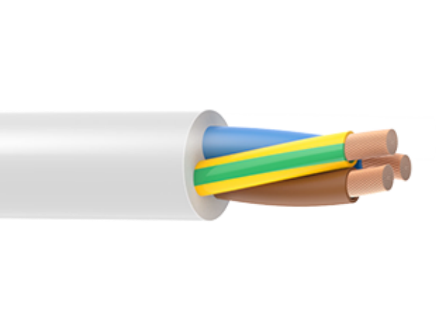
H05VV-F
H05VV-F wires from NPC Electric are flexible PVC insulated and sheathed cables designed for light-duty power connections in household and commercial electrical equipment. Featuring finely stranded copper conductors, these wires provide excellent flexibility, making them easy to install and suitable for applications involving frequent movement. The double PVC insulation structure offers reliable electrical protection, good mechanical strength, and resistance to abrasion, ensuring safe operation under normal indoor conditions. Manufactured in accordance with harmonized standards, NPC Electric H05VV-F wires deliver stable conductivity, consistent insulation thickness, and dependable performance. They are widely used where flexibility, safety, and ease of handling are essential, making them a practical choice for appliances, extension cords, and portable equipment.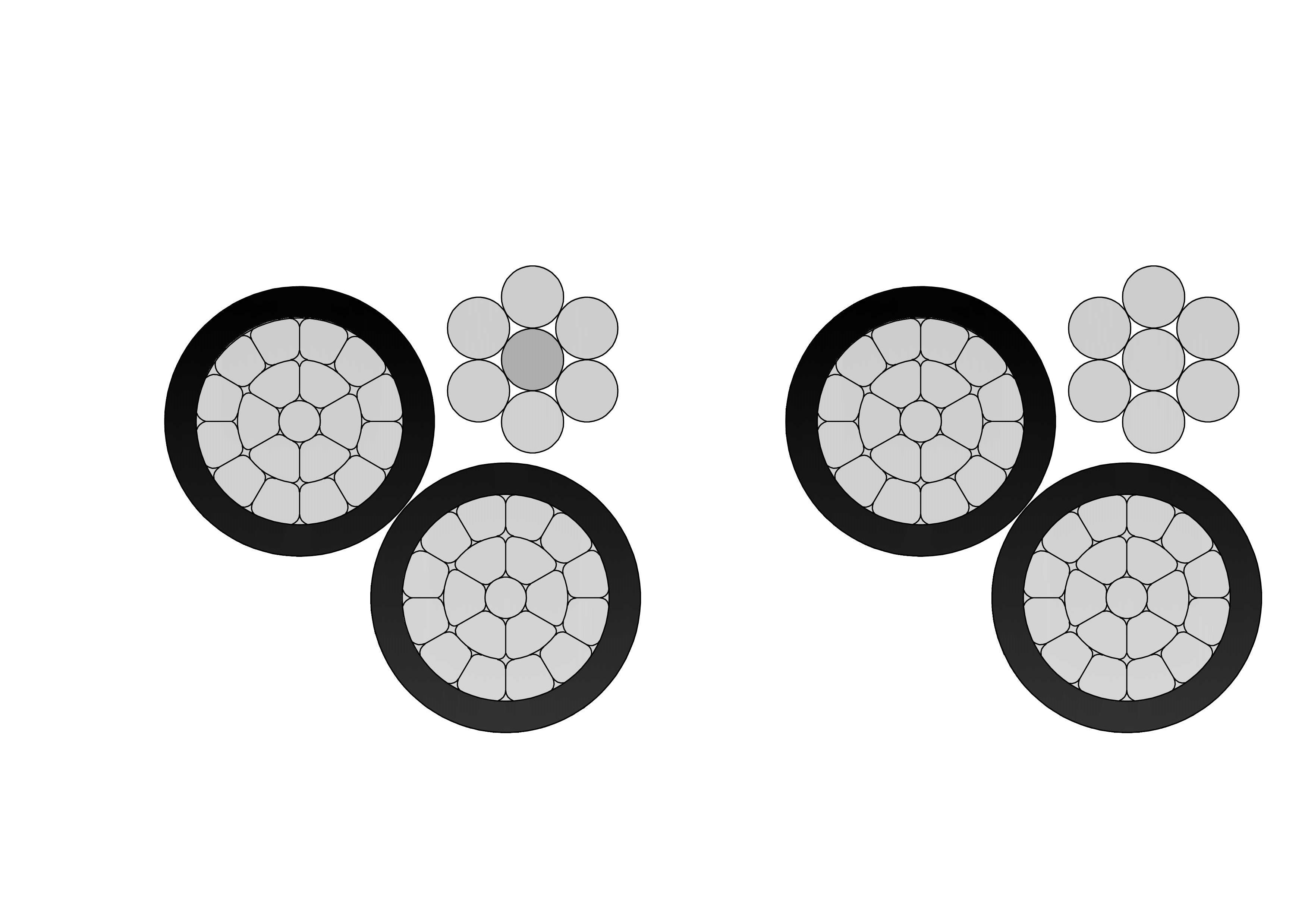
6 Paludina Aluminum Conductor Triplex Overhead Service Drop Cable
The 6 Paludina Aluminum Conductor Triplex Overhead Service Drop Cable is engineered for safe and efficient overhead service drop installations. It features two insulated aluminum phase conductors twisted around a reinforced neutral messenger, delivering balanced electrical performance and strong mechanical support. This cable offers lightweight construction, corrosion resistance, and excellent weatherability. The insulation system of the 6 Paludina Aluminum Conductor Triplex Overhead Service Drop Cable provides long-term protection against sunlight, moisture, and temperature fluctuations, reducing maintenance costs and extending service life. A complete quality assurance system governs the manufacturing process, integrating raw material testing, process inspection, and finished product testing. Each production stage follows strict control procedures to ensure consistent compliance with international standards and utility specifications. The 6 Paludina Aluminum Conductor Triplex Overhead Service Drop Cable is a dependable choice for modern overhead power distribution networks.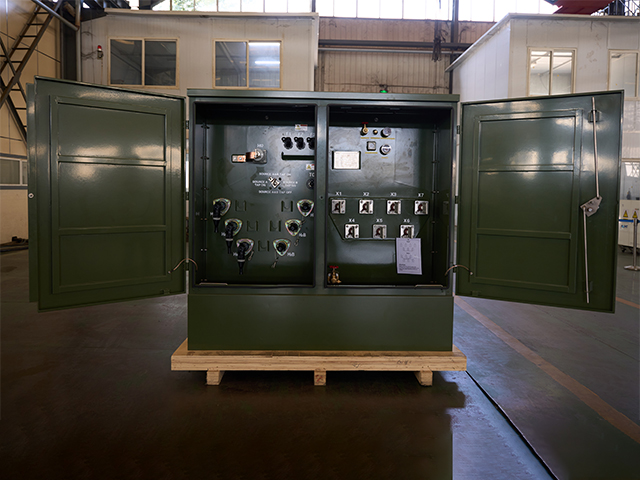
150kVA Three Phase Pad Mounted Transformer
The 150kVA Three Phase Pad Mounted Transformer is a compact, liquid-immersed distribution transformer engineered for dependable underground power supply in commercial, institutional, and light industrial environments. It supports primary voltages from 4160V to 34500GrdY/19920 (common configurations include 12470GrdY/7200, 13800 Delta, or 24940GrdY/14400), stepping down to secondary voltages such as 208Y/120V, 480Y/277V, 240/120V Delta with center tap, or 416Y/240V.
LiYCY Control Cable - Screened Flexible PVC Control Cable
The LiYCY Control Cable is a high-quality screened flexible control cable widely used in industrial automation and machinery applications. It features finely stranded copper conductors with PVC insulation, twisted cores, a tinned copper braid screen for superior electromagnetic interference (EMI) protection, and a durable PVC outer sheath. This construction provides excellent flexibility, reliable signal transmission, and effective shielding against electrical noise. Rated 300/500V, the LiYCY Control Cable is ideal for dynamic installations and environments requiring both mechanical flexibility and EMI protection. Manufactured to international standards such as VDE 0812 and IEC 60227, it undergoes rigorous quality testing from raw materials to finished product, ensuring consistent electrical performance, mechanical strength, and long-term reliability in demanding industrial control applications.
4/0 AWG OXLIP AAC Cable
The 4/0 AWG OXLIP AAC Cable is a premium All Aluminum Conductor designed for efficient overhead power transmission and distribution lines. Manufactured with seven strands of high-purity 1350-H19 aluminum wire in a concentric lay configuration, this bare conductor delivers outstanding electrical performance with low DC resistance of 0.0817 ohms per 1000 ft at 20°C. Featuring an overall diameter of 0.522 inches and a rated breaking strength of 3,830 lbs, the OXLIP AAC provides a robust ampacity of 383 amps while maintaining a lightweight profile of 198.6 lbs per 1000 ft. Its excellent strength-to-weight ratio minimizes sag and reduces structural loading. Fully compliant with ASTM B-230 and B-231 standards, the 4/0 AWG OXLIP AAC Cable offers superior corrosion resistance for long-term durability in harsh outdoor environments, making it an ideal choice for utility networks seeking cost-effective, high-reliability bare aluminum conductors.
4 Spaniel Aluminum Conductor Duplex Overhead Service Drop Cable
Introducing the 4 Spaniel Duplex Service Drop Cable, a versatile overhead solution for low-voltage secondary distribution. Built with two 4 AWG aluminum conductors (7-strand) insulated with polyethylene or XLPE and formed into a duplex assembly, it meets ASTM and ICEA requirements for 600V service. The tough insulation offers outstanding protection against UV rays, moisture, tree contact, and abrasion. Compact duplex design provides self-support and easy pulling during installation. The 4 Spaniel Duplex Service Drop Cable supports efficient power transfer with low voltage drop and high durability in extreme temperatures. Popular for its lightweight construction and reduced installation time, it is the go-to choice for electricians and utilities. Widely deployed in housing developments, farm services, and temporary power setups, this cable ensures safe, long-lasting overhead connections from distribution transformers to customer service entrances worldwide.
Low Voltage Withdrawable Switch Cabinet
The Low Voltage Withdrawable Switch Cabinet is a state-of-the-art power distribution solution designed for safe, flexible, and efficient low-voltage electrical systems. Featuring modular withdrawable drawers (functional units), it allows quick extraction and insertion of circuit breakers, contactors, and other components without interrupting power to the entire system. This design significantly reduces downtime during maintenance, enhances operational safety, and supports high-reliability applications in modern industrial and commercial facilities. Built with robust compartmentalized construction, high-quality busbar systems, and advanced safety interlocks, the cabinet ensures excellent short-circuit withstand capability, thermal performance, and protection against arc faults. It integrates seamlessly with intelligent monitoring systems for real-time data on current, voltage, power quality, and predictive maintenance. Ideal for motor control centers (MCC) and power control centers (PC), this withdrawable switchgear optimizes space utilization while delivering superior flexibility for future expansions or modifications.
954 MCM Magnolia AAC Cable
The 954 MCM Magnolia AAC Cable is a high-performance All Aluminum Conductor designed for demanding overhead power transmission and distribution lines. Manufactured with 37 strands of premium 1350-H19 aluminum wire in a concentric lay configuration, this bare conductor provides excellent electrical conductivity with a low DC resistance of 0.0181 ohms per 1000 ft at 20°C. Featuring an overall diameter of 1.124 inches and a rated breaking strength of 16,400 lbs, the Magnolia AAC delivers a robust ampacity of 982 amps while weighing only 895.6 lbs per 1000 ft. Its optimized strength-to-weight ratio minimizes sag and structural loading. Fully compliant with ASTM B-230 and B-231 standards, the 954 MCM Magnolia AAC Cable offers outstanding corrosion resistance for long-term durability in harsh outdoor environments, making it the preferred choice for utility networks requiring cost-effective, high-reliability bare aluminum conductors.Welcome your inquiry
Honesty, Integrity, Frugality, Activeness and Passion