Wind Transformer Design Complete Guide: Principles to Wind Power Special Requirements
2026-05-01
1. Wind Energy Transformation
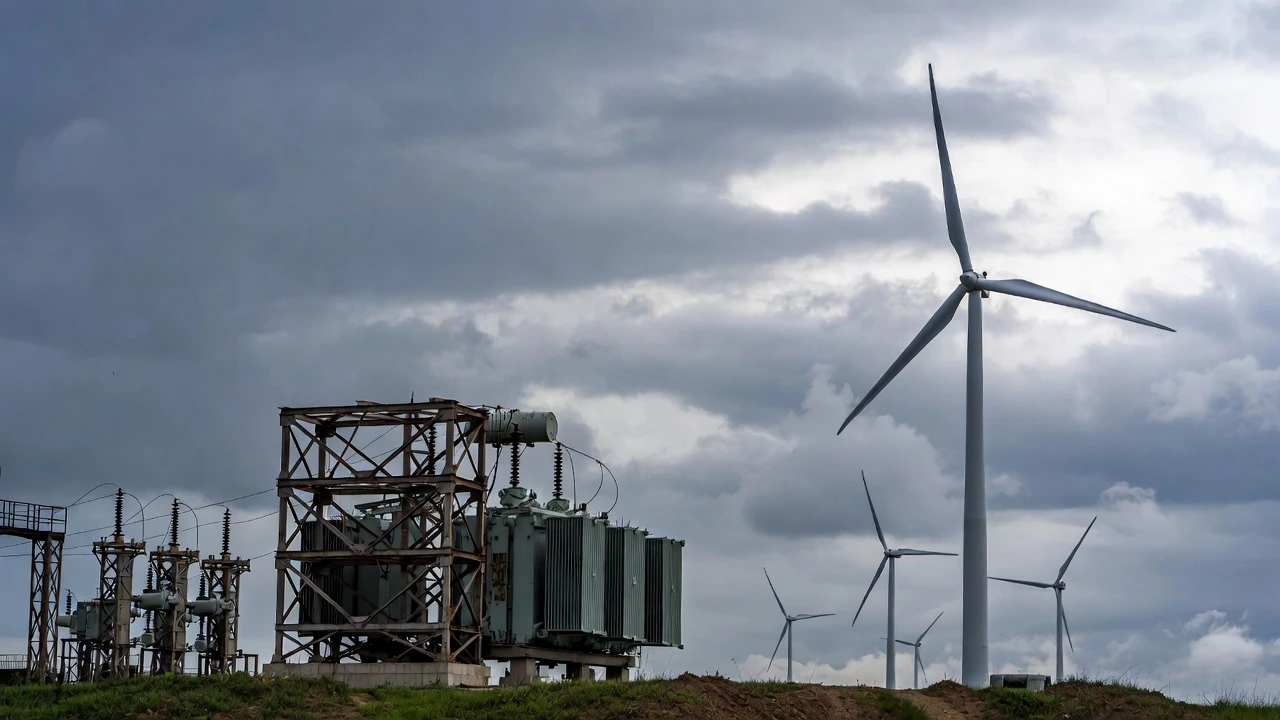
Wind Energy Transformer, commonly known as a Wind Turbine Transformer or Wind Power Step-up Transformer, serves as a critical component in modern wind power generation systems. It steps up the low-voltage output (typically 690 V to 1.2 kV) from the wind turbine generator to medium or high voltage levels (10 kV–66 kV or higher), enabling efficient power collection, long-distance transmission, and grid integration while minimizing line losses.
Unlike conventional distribution transformers, wind energy transformers must withstand unique operational challenges: highly variable loads due to fluctuating wind speeds (frequent transitions from no-load to full-load), harmonic-rich and non-sinusoidal currents from power electronics, repeated switching transients, low-voltage ride-through (LVRT) requirements, and — especially in offshore applications — extreme conditions including vibration, salt mist corrosion, humidity, and limited space in nacelles or towers.
Design standards such as IEC/IEEE 60076-16 (covering wind turbine step-up transformers up to 72.5 kV) guide specialized features: reinforced insulation, optimized winding structures for resonance suppression, low partial discharge, enhanced short-circuit withstand capability, and multi-physics optimization (electromagnetic, thermal, mechanical coupling).
Common types include:
- Dry-type transformers (cast-resin or encapsulated): Fire-safe, maintenance-free, compact, and ideal for offshore/large-capacity turbines (e.g., 66 kV systems in 15–20+ MW units).
- Oil-immersed transformers (often pad-mounted or substation-style): Excellent cooling and cost-effective for onshore farms, though requiring leak prevention and environmental safeguards.
As offshore wind scales toward 20 MW+ turbines and collection voltages reach 66 kV+, dry-type designs dominate trends for reliability, reduced losses, and eco-friendly performance. In 2025–2026, advancements focus on higher efficiency, lower no-load losses, harmonic mitigation, and integration with flexible low-frequency grids.
Ultimately, the wind energy transformer is far more than a voltage converter — it ensures stable, efficient, and long-life operation of wind farms, making mastery of its special design requirements essential for renewable energy engineers and developers.
2. Role of Wind Transformer in Wind Power Systems
In modern wind power systems, the transformer performs several critical functions:
- Step up low generator voltage to medium or high voltage
- Provide voltage regulation
- Ensure insulation coordination
- Support fault ride-through capability
- Integrate with power electronics converters
The wind turbine transformer, also known as a wind power transformer, is typically located:
- Inside the nacelle
- At the tower base
- In a dedicated transformer substation
3. Energy Transformation in a Wind Turbine to Create Electricity
Energy transformation in a wind turbine is the process of converting the kinetic energy of moving air (wind) into usable electrical energy through a series of efficient steps. This clean, renewable conversion powers millions of homes worldwide and is central to sustainable wind power generation.
Kinetic Energy from Wind: Wind possesses kinetic energy due to its motion. As wind flows over the specially shaped turbine blades (aerodynamically designed like airplane wings), it creates lift and drag forces that cause the blades to rotate.
Kinetic to Rotational (Mechanical) Energy: The spinning rotor (hub + blades) transfers this motion to a low-speed shaft, turning kinetic energy into rotational mechanical energy. In geared turbines, a gearbox increases rotation speed (from ~10-25 rpm to 1,000-1,800 rpm); direct-drive models skip this step for higher reliability.
Mechanical to Electrical Energy: The high-speed shaft drives a generator inside the nacelle. Using electromagnetic induction (Faraday's law), rotating magnets induce an electric current in stationary wire coils, converting mechanical energy directly into alternating current (AC) electricity.
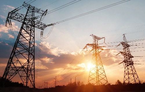
Final Grid Integration: A transformer steps up the low-voltage output (e.g., 690V) to medium/high voltage (e.g., 33kV–66kV+) for efficient transmission to the power grid, minimizing losses.
This multi-stage energy transformation—kinetic → rotational mechanical → electrical—achieves high efficiency (up to 50-60% in modern turbines) while producing zero emissions during operation. Understanding these steps highlights why wind turbines are a cornerstone of the global shift to renewable energy.
Understanding wind turbine energy transformation clarifies transformer requirements.
3.1 Process Overview
- Wind kinetic energy (variable wind speeds)
- Rotor mechanical rotation
- Shaft drives wind turbine generator
- Generator produces low-voltage electrical energy
- Wind turbine step up transformer increases voltage
- Transmission to collection system
3.2 Simplified Wind Turbine Transformer Diagram (Conceptual)
|
Stage |
Energy Form |
Key Equipment |
|
Aerodynamic |
Kinetic |
Blades |
|
Mechanical |
Rotational |
Gearbox |
|
Electrical |
Low Voltage |
Wind turbine generator |
|
Voltage Transformation |
Medium Voltage |
Step up transformer |
The transformer must handle variable power output due to changing wind speeds.
4. Wind Turbine Step Up Transformer Design
Wind Turbine Step-Up Transformer Design focuses on specialized transformers (also called generator step-up or GSU transformers) that boost low-voltage output from wind turbine generators (typically 690V–1.2kV) to medium voltages (10kV–66kV+), enabling efficient power collection and grid integration in wind farms.
Unlike standard distribution transformers, wind turbine step-up transformer design must address unique challenges: frequent load fluctuations from variable wind speeds, harmonic distortions from power converters, transient overvoltages during switching, low-voltage ride-through (LVRT) compliance, resonance risks, vibration (especially offshore), and enhanced short-circuit withstand. Key standards include IEC 60076-16 for tailored requirements.
Design considerations include optimized windings (e.g., disc for HV strength), reinforced insulation, resonance suppression via adjusted clearances, low-loss cores, and multi-physics optimization (electromagnetic-thermal-mechanical). Common types: dry-type (cast-resin, compact, fire-safe for nacelle/offshore) and oil-immersed (pad-mounted, efficient cooling for onshore).
As turbines scale to 15–20MW+, designs emphasize higher voltages (66kV+), compactness, reliability, and reduced failures for sustainable wind energy performance.
Most wind turbine generators produce 690V–1kV output. For grid connection, voltage must be raised to:
- 10kV
- 20kV
- 33kV
In large wind farms, further step-up to 110kV or higher may occur at substations.
4.1 Electrical Design Parameters
|
Parameter |
Typical Value |
|
Rated Power |
1–8 MVA (per turbine) |
|
Primary Voltage |
690V |
|
Secondary Voltage |
10–35kV |
|
Frequency |
50Hz / 60Hz |
|
Cooling |
ONAN / ONAF / Dry type |
The wind turbine step up transformer must tolerate harmonics from converters.
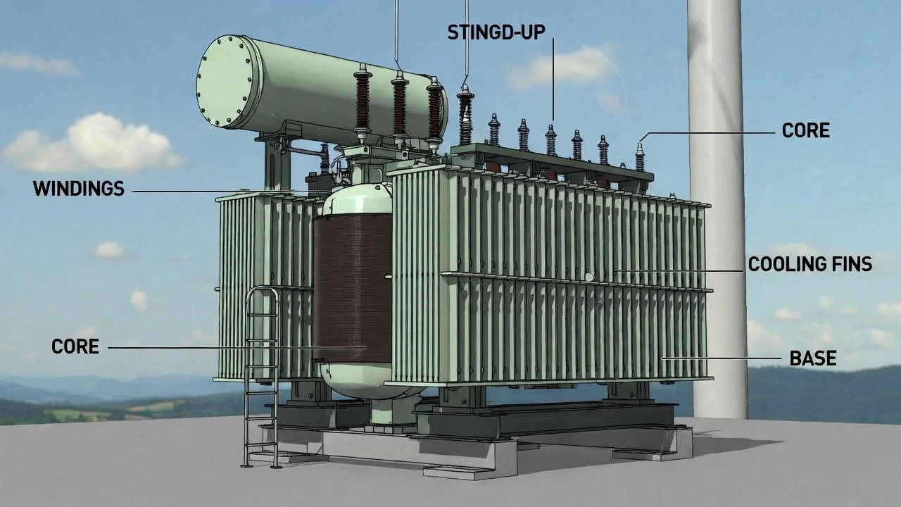
5. Transformer Winding and Core Engineering
5.1 Transformer Winding Structure
The transformer winding design directly affects efficiency and reliability.
|
Winding Type |
Application |
|
Layer winding |
Low voltage |
|
Disc winding |
Medium voltage |
|
Continuous winding |
High voltage |
Stranded copper conductors are commonly used for improved thermal performance.
5.2 Core Design
Wind transformers use:
- CRGO silicon steel core
- Low-loss laminated structure
- Optimized flux density
Efficiency is critical for long term wind farm profitability.
6. Wind Turbine Transformer Insulation System
The wind turbine transformer insulation system must withstand:
- Voltage surges
- Switching transients
- Partial discharge
- High altitude installation
Typical insulation materials include:
- Kraft paper
- Epoxy resin
- Nomex
- Mineral oil
Insulation coordination follows IEC 60076 standards.
7. Dry-Type vs Oil-Immersed: How to Select
In wind transformer applications, choosing between dry-type and oil-immersed designs is critical for reliability, safety, and efficiency in onshore/offshore wind farms.
Dry-Type (cast-resin/epoxy):
- Superior fire safety (no oil, flame-retardant)
- Low maintenance, eco-friendly (no spill risk)
- Compact, vibration-resistant — ideal for offshore nacelle/tower mounting or enclosed spaces
- Better for harsh marine environments (salt mist, humidity)
- Follows IEC 60076-16; common in 66kV+ large turbines (15–20MW+)
Oil-Immersed:
- Superior cooling → higher efficiency, overload capacity, lower losses
- Cost-effective for large capacities
- Better for onshore pad-mounted or substation use
- Requires leak prevention, fire safeguards
How to Select: Offshore/large offshore → dry-type for safety/compactness. Onshore/high-load → oil-immersed for efficiency/cost. Evaluate LVRT, harmonics, vibration, and environment per IEC 60076-16.
One of the most critical decisions in wind transformer design is selecting between dry type transformer and oil immersed transformer.
7.1 Comparison Table
|
Feature |
Dry Type Transformer |
Oil Immersed Transformer |
|
Cooling |
Air |
Mineral oil |
|
Fire Risk |
Low |
Moderate |
|
Maintenance |
Low |
Requires oil monitoring |
|
Overload Capacity |
Moderate |
High |
|
Offshore Suitability |
Limited |
Widely used |
|
Cost |
Higher |
Cost-effective |
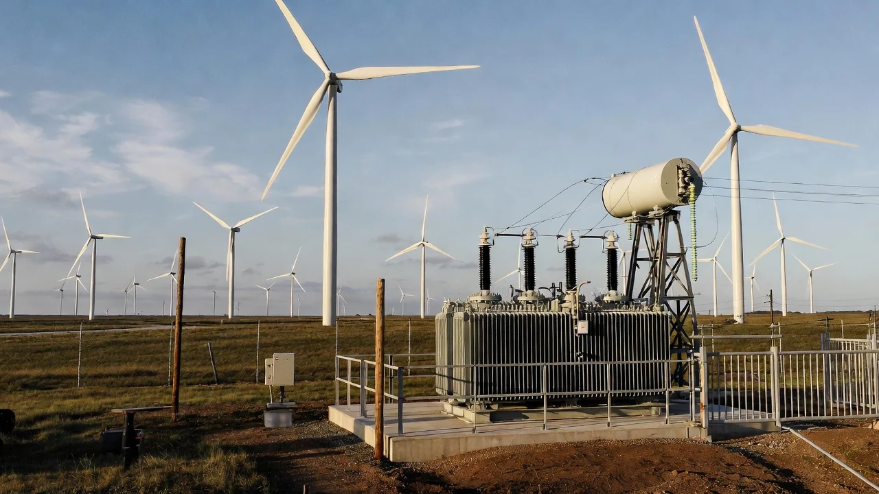
For nacelle-mounted transformers, dry type may be preferred due to fire safety.
For ground-mounted transformers in wind farms, oil-immersed designs dominate.
8. Three Winding Transformer in Wind Farms
In large wind farms, a three winding transformer may be used.
Advantages:
- Connect multiple voltage levels
- Reduce substation footprint
- Improve system flexibility
|
Winding |
Voltage Level |
|
LV |
Generator side |
|
MV |
Collection system |
|
HV |
Grid transmission |
This configuration enhances system integration efficiency.
9. Voltage Regulation and Power Electronics Integration
Voltage regulation and power electronics integration are vital in wind turbine step-up transformers (wind transformers) to ensure stable grid connection amid variable wind speeds and converter harmonics. Power electronics (e.g., back-to-back converters in DFIG/PMSG systems) handle variable frequency/voltage from the generator, enabling LVRT, reactive power support, and frequency/voltage control.
The transformer interfaces post-converter, often with on-load tap changers (OLTC) for dynamic voltage adjustment, resonance suppression, and harmonic mitigation. Integration optimizes grid compliance (e.g., IEC 60076-16), reduces losses, enhances stability, and supports reactive power/Q control via converters or auxiliary devices.
Key benefits: Maintains voltage within limits during fluctuations, improves power quality, enables fault ride-through, and boosts overall wind farm efficiency in modern variable-speed turbines.
Modern wind power systems rely heavily on power electronics.
Challenges include:
- Harmonic distortion
- Voltage fluctuations
- Reactive power compensation
The wind transformer must support:
- Dynamic voltage regulation
- Low impedance
- High short-circuit strength
Proper impedance selection ensures grid stability.
10. Offshore Wind Turbines: Special Requirements
Offshore wind turbines introduce additional design complexity.
10.1 Environmental Challenges
- Salt corrosion
- High humidity
- Mechanical vibration
- Temperature variation
10.2 Offshore Transformer Features
|
Requirement |
Solution |
|
Corrosion protection |
Marine-grade coating |
|
Compact size |
Space-optimized design |
|
High voltage transmission |
66kV or higher |
|
Long term reliability |
Enhanced insulation system |
Offshore applications demand superior sealing and monitoring systems.
11. Testing Standards and Long Term Reliability
Wind transformers must pass rigorous testing:
- Ratio test
- Winding resistance
- Impulse test
- Temperature rise test
- Partial discharge test
Long term reliability depends on:
- Insulation aging resistance
- Load cycle endurance
- Thermal design margin
Wind farms typically expect 20–25 years service life.
12. Practical Selection Guide for International Projects
When selecting transformers for wind projects, engineers should evaluate:
- Rated power output per turbine
- Grid connection voltage
- Installation environment
- Wind speeds variability
- Offshore vs onshore application
- Maintenance strategy
- Long term cost analysis
A wind transformer is a specialized component engineered for dynamic renewable energy conditions. From managing energy transformation in a wind turbine to create electricity, to stabilizing high voltage transmission in large wind farms, its design must integrate advanced insulation, optimized transformer winding, and compatibility with power electronics.
Whether selecting a wind turbine transformer, designing a three winding transformer for grid integration, or choosing between dry-type vs oil-immersed: how to select, engineers must consider operational stress, environmental exposure, and long term reliability.
As global renewable energy capacity expands—particularly in offshore wind turbines—transformers for wind high voltage systems will remain a critical technology enabling stable and efficient wind power generation worldwide.
Related Articles


Related Products
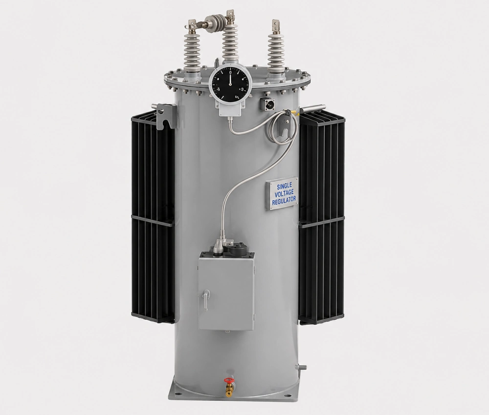
Three Phase Automatic Step Voltage Regulator
The Three Phase Automatic Step Voltage Regulator is a high-performance on-load tap changing device designed to automatically maintain stable voltage levels in medium-voltage distribution networks. Equipped with premium copper windings, low-loss silicon steel cores, and a reliable motorized on-load tap changer, it delivers fast, precise voltage correction with minimal waveform distortion. The intelligent digital controller continuously monitors three-phase voltage and load conditions, making real-time adjustments to ensure consistent output voltage despite fluctuations in supply or demand. Built for outdoor durability, it features a fully sealed oil-immersed tank with advanced corrosion protection, excellent overload capability, and comprehensive protection systems. This regulator significantly improves power quality, reduces line losses, and enhances equipment lifespan across distribution systems.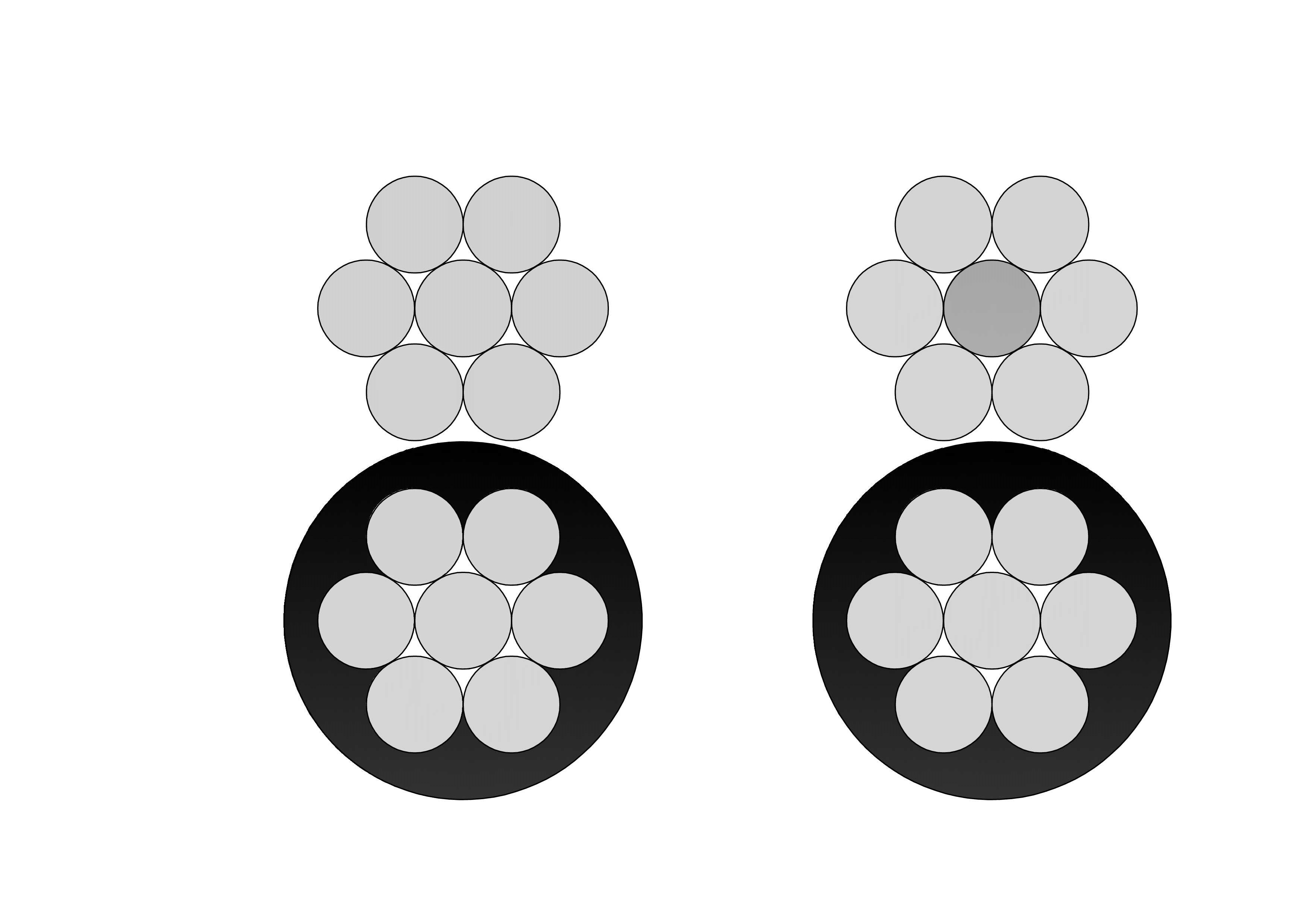
6 Setter Aluminum Conductor Duplex Overhead Service Drop Cable
6 Setter Aluminum Conductor Duplex Overhead Service Drop Cable is designed for reliable secondary overhead power delivery from utility distribution lines to residential and light commercial service entrances. The duplex construction consists of two stranded aluminum conductors, typically functioning as a phase conductor and a neutral messenger, providing both electrical transmission and mechanical support. The No. 6 Setter conductor size offers balanced current-carrying capability, controlled sag, and adequate tensile strength for short-span service drop installations. Aluminum construction ensures reduced weight, excellent corrosion resistance, and ease of handling during installation in outdoor environments. Manufactured in compliance with ASTM standards and utility specifications, the 6 Setter Aluminum Conductor Duplex Overhead Service Drop Cable features uniform stranding, stable electrical performance, and long-term durability. It is widely used by utilities and electrical contractors seeking a cost-effective, dependable solution for overhead service drop applications.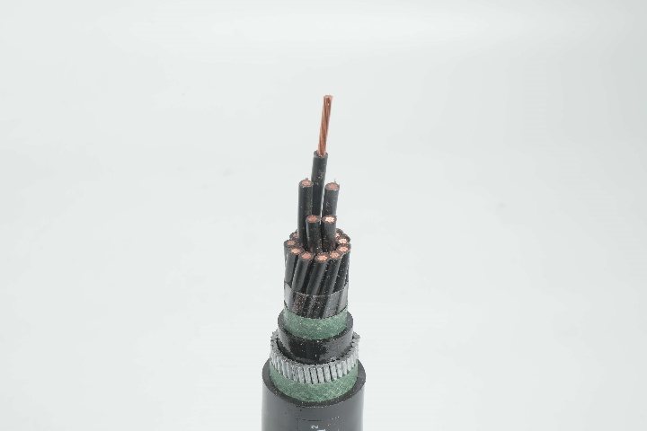
LiYCY Control Cable - Screened Flexible PVC Control Cable
The LiYCY Control Cable is a high-quality screened flexible control cable widely used in industrial automation and machinery applications. It features finely stranded copper conductors with PVC insulation, twisted cores, a tinned copper braid screen for superior electromagnetic interference (EMI) protection, and a durable PVC outer sheath. This construction provides excellent flexibility, reliable signal transmission, and effective shielding against electrical noise. Rated 300/500V, the LiYCY Control Cable is ideal for dynamic installations and environments requiring both mechanical flexibility and EMI protection. Manufactured to international standards such as VDE 0812 and IEC 60227, it undergoes rigorous quality testing from raw materials to finished product, ensuring consistent electrical performance, mechanical strength, and long-term reliability in demanding industrial control applications.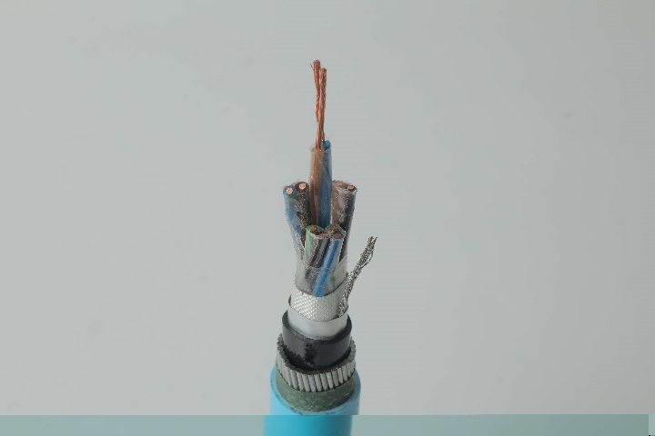
Instrumentation Cables—XLPE Insulated, Overall Screened ,Unarmoured PVC Sheathed Cables(CU/XLPE/OSCR/PVC)
Instrumentation cables come in twisted pairs, triads, and quads, depending on the customer’s applications; twisting reduces any electromagnetic interference by reducing the chances of electrical voltages and currents being induced in the conductor. Individual and overall screening are also applied in instrumentation cables to optimize the signal transferred and further reduce any electromagnetic interference. Screening of pairs, triads, or quads also includes a drain wire earthed to the ground, which ensures a noise-free signal transmission. Depending on the application, instrumentation cables can be insulated with PVC or XLPE; the cables can be armoured or unarmoured. The sheathing materials can be of PVC, LSZH, or PE. The cables can have additional flame retardant or flame retardant properties, and they can be manufactured with special protections such as lead sheaths, or DRYLAM or AIRBAG technology.
35kV Oil Immersed Transformer
NPC ELECTRIC's 35kV Oil Immersed Transformer is a premium three-phase power transformer optimized for high-voltage step-down in 50/60Hz AC systems with primary ratings of 35kV (or 33-38.5kV range). It incorporates a robust conservator or fully sealed tank design with efficient radiator cooling (ONAN standard, ONAF optional), ensuring exceptional thermal dissipation, moisture exclusion. Outdoor-rated with pollution-resistant bushings (BIL 170-200kV), Dyn11/Ynd1 vector groups, and low noise (<62dB), it provides stable 35kV to secondary voltages (e.g., 10kV/6.3kV/0.4kV) conversion, enhancing grid stability, minimizing transmission losses, and supporting demanding applications in harsh or high-altitude conditions.
138kV / 140kV / 150kV Three-Phase Oil-Immersed Power Transformer
The 138kV / 140kV / 150kV Three-Phase Oil-Immersed Power Transformer is designed to serve high-voltage transmission and substation applications requiring dependable energy transfer and long-term operational stability. Its design emphasizes electrical reliability, structural strength, and efficient thermal management to support continuous service under varying grid loads. The transformer employs a refined magnetic circuit and carefully engineered winding structure to maintain voltage accuracy while minimizing operational stress. An oil-immersed insulation and cooling system ensures effective heat dissipation and insulation integrity throughout extended operating cycles. Built for outdoor installation, the transformer is capable of withstanding environmental exposure, electrical fluctuations, and mechanical demands associated with modern high-voltage networks. It is suitable for utility-scale projects where safety, efficiency, and durability are essential performance criteria.
Copper Conductor Quadruplex Service Drop Cable 600V
Copper Conductor Quadruplex Overhead Service Drop Cable is designed for 600V phase-to-phase electrical distribution, primarily used to carry power from pole-mounted transformers to the customer's service entrance. Comprising three insulated copper phase conductors and one copper neutral messenger (stranded) with XLPE or PE insulation in quadruplex form, it meets ASTM, ICEA, and international standards. High-purity copper ensures minimal voltage drop and excellent current capacity. Robust insulation resists sunlight, moisture, and mechanical damage for decades of outdoor service. Self-supporting design allows easy installation with low sag. The Copper Conductor Quadruplex Service Drop Cable 600V provides reliable power transfer up to 600V in extreme temperatures. Flame-retardant options enhance safety. Commonly chosen for premium single-phase and three-phase power delivery in subdivisions, rural homes, commercial connections, and critical installations requiring high-conductivity copper overhead solutions with proven longevity and performance.
161kV 50MVA Two-Winding Power Transformer – Efficient Oil-Filled Design with OLTC
The 161kV 50MVA Two-Winding Power Transformer is engineered to deliver precise voltage control and stable power transfer in high-voltage transmission and substation networks. Featuring an oil-filled insulation system combined with an On-Load Tap Changer (OLTC), this transformer allows continuous voltage adjustment under load conditions without interrupting system operation. The electromagnetic design emphasizes low losses, high operational efficiency, and consistent performance across variable load profiles. Robust mechanical construction enhances resistance to thermal expansion and short-circuit forces, ensuring long-term reliability in demanding grid environments. Optimized oil circulation supports effective heat dissipation, contributing to extended service life and reduced maintenance requirements. This transformer is well suited for modern power systems where voltage stability, operational flexibility, and dependable energy transmission are critical.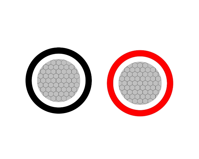
Photovoltaic Solar H1Z2Z2-K Cable
H1Z2Z2-K is a single-core DC 1500V cable specially designed for photovoltaic systems. It is widely used for connections between solar panels and inverters in solar power installations. Compliant with EN 50618 and IEC 62930 standards, it is suitable for indoor and outdoor use, both in fixed and mobile installations, and can withstand harsh environmental conditions. For installations where fire, smoke emissions, and toxic fumes create a potential risk to life and equipment, Water resistant to AD8.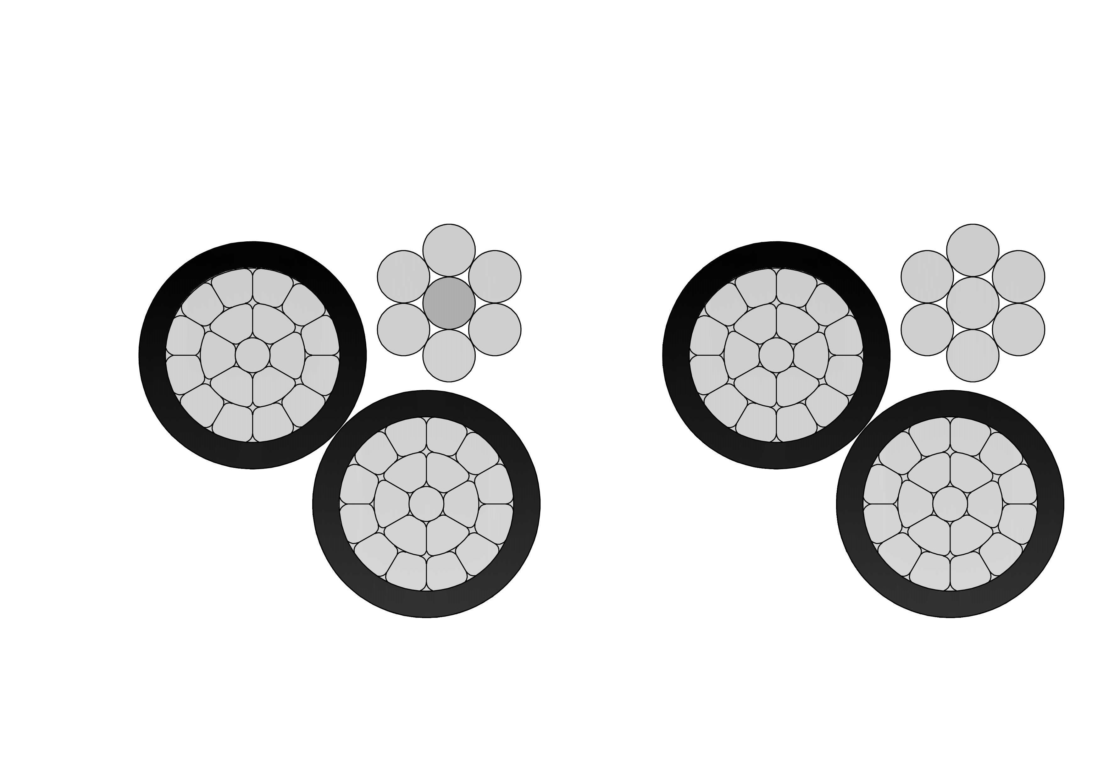
3/0 Fulgar Aluminum Conductor Triplex Overhead Service Drop Cable
3/0 Fulgar Aluminum Conductor Triplex Overhead Service Drop Cable is engineered for high-capacity overhead electrical service connections in utility distribution systems. The cable consists of two insulated aluminum phase conductors twisted around a bare aluminum neutral messenger, ensuring stable electrical transmission and strong mechanical support. Manufactured using high-purity aluminum and weather-resistant insulation compounds, the 3/0 Fulgar Aluminum Conductor Triplex Overhead Service Drop Cable delivers low electrical resistance, excellent corrosion resistance, and reliable long-term performance in outdoor environments. Its optimized conductor design allows efficient installation while maintaining the tensile strength required for aerial service applications. The cable is designed to withstand UV exposure, wind loading, and temperature fluctuations. Comprehensive quality control procedures and systematic testing are applied throughout the manufacturing process to ensure compliance with industry and utility standards and dependable field operation.
CANTON AAAC Conductor Cable
CANTON AAAC (All Aluminum Alloy Conductor) cables are manufactured in accordance with ASTM B399 standards, offering high tensile strength, good electrical conductivity, and corrosion resistance. With 800 mm² nominal area and 61-strand design, it uses heat-treated aluminum-magnesium-silicon alloy (6201-T81) for enhanced strength (295 MPa min) and conductivity (53% IACS min). Meeting ASTM B398, B399, IEC 61089, and BS EN 50182 standards, this cable handles ampacity up to 1200A at 75°C and voltages up to 33kV. The all-alloy construction avoids bimetallic corrosion, providing better resistance in harsh conditions than ACSR. Reduced weight minimizes sag and installation expenses, supporting longer spans. The Canton AAAC Conductor Cable delivers low electrical losses, high mechanical endurance, and excellent weather tolerance. Flame-retardant variants available. Perfect for urban grids, renewable projects, and coastal setups, it provides cost-effective, low-maintenance power delivery in overhead applications globally, excelling in reliability and lifespan over conventional conductors.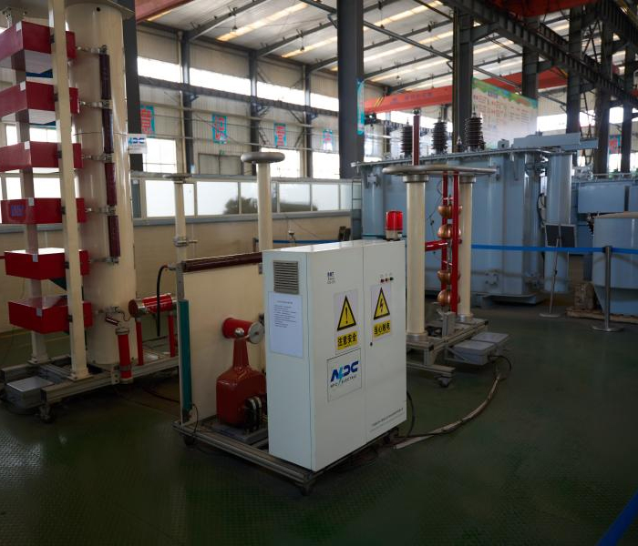
10kV Cast Resin Dry Type Transformer Copper Winding
The 10kV Cast Resin Dry Type Transformer Copper Winding, a high-reliability, oil-free power solution engineered for safe and efficient indoor medium-voltage distribution. This three-phase dry-type transformer features fully vacuum-cast epoxy resin encapsulation around high-purity copper windings, combined with premium low-loss grain-oriented silicon steel cores to deliver exceptional energy efficiency (typically 98%+), significantly reduced no-load and load losses, and outstanding partial discharge performance (<10pC). The cast resin design ensures superior moisture resistance, self-extinguishing fire safety (F1 class), robust short-circuit withstand, and maintenance-free operation. Natural air (AN) cooling with optional forced air (AF) upgrades supports high overload capacity while maintaining low acoustic emissions through advanced vibration isolation and optimized core/winding geometry. Compliant with IEC 60076-11 and equivalent standards, this transformer steps down 10kV primary (with ±2×2.5% or wider off-circuit taps) to 0.4kV secondary (Dyn11 vector group standard), making it the ideal choice for modern commercial, industrial, and utility indoor installations prioritizing safety, sustainability, and long-term performance.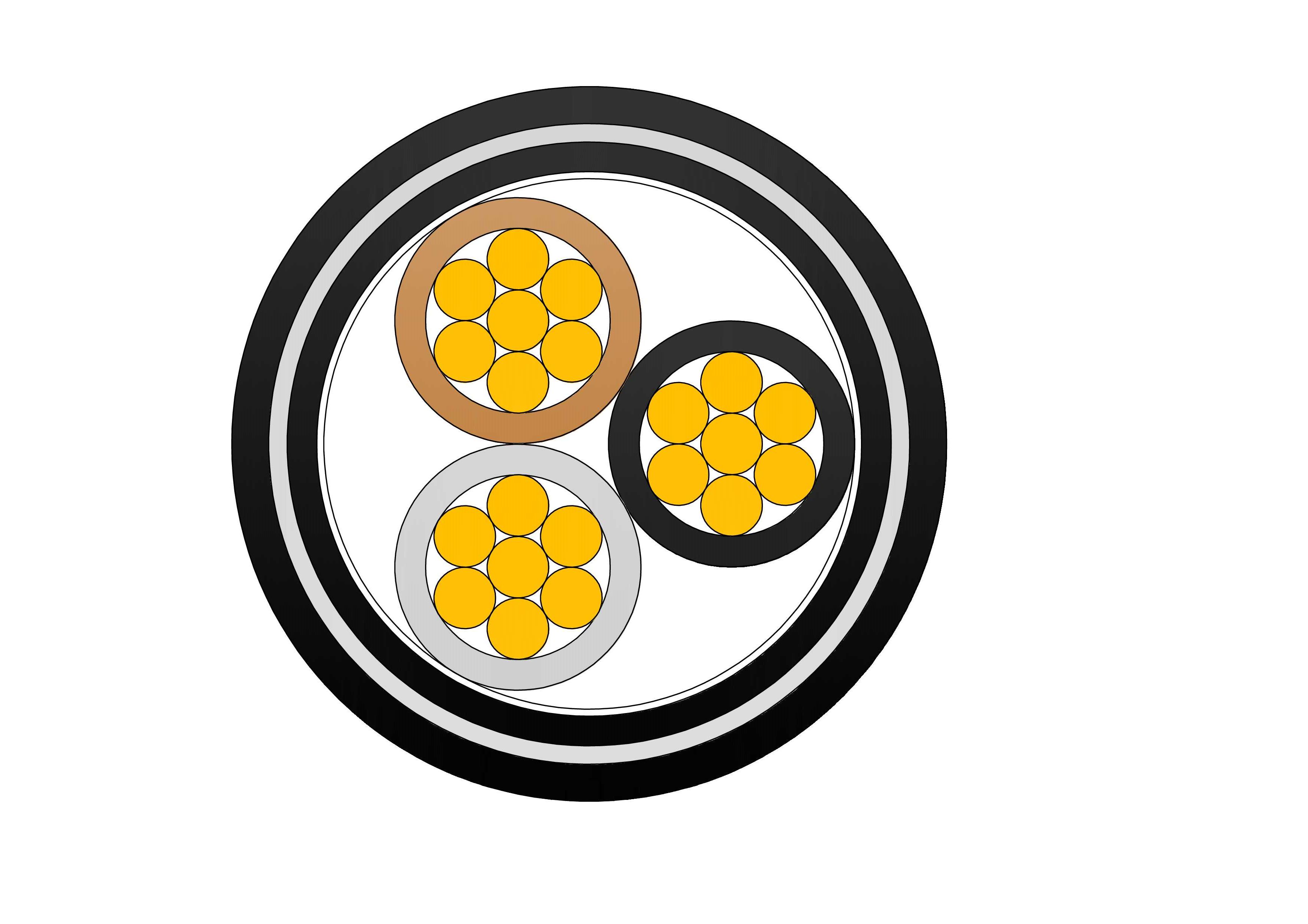
NYBY 0.6/1kV Low Voltage Power Cable
NYBY 0.6/1kV are low voltage power cables designed according to IEC 60502-1 standard, suitable for fixed installation in indoor, outdoor, underground, cable ducts, or concrete environments, with steel tape armoring for enhanced mechanical protection. Constructed with copper conductors, PVC core insulation, filling, galvanized steel wire armour, and tough PVC outer sheath, it meets VDE 0276 and IEC requirements. The SWA layer offers outstanding resistance to mechanical damage, enabling direct burial without additional conduits. Copper ensures minimal losses and high current rating. Flame-retardant and stable in moist conditions, the NYBY 0.6/1kV Low Voltage Power Cable is widely used in factories, renewable energy sites, commercial complexes, and infrastructure needing reliable, long-service-life low-voltage cabling with enhanced safeguarding in aggressive soils or high-risk areas.
230kV 3-Phase Step-Down Power Transformer
The 230kV 3-Phase Step-Down Power Transformer is designed to reduce high transmission voltages to suitable distribution levels while maintaining excellent efficiency and operational stability. Engineered for utility substations and large-scale grid interfaces, this transformer ensures safe and controlled power delivery from high-voltage networks to regional or industrial distribution systems. Its oil-immersed insulation system provides strong dielectric protection and efficient thermal dissipation, enabling reliable continuous operation under varying load conditions. Precision core construction and optimized winding layout help minimize energy losses and voltage fluctuation. The transformer’s robust mechanical design enhances resistance to short-circuit forces and thermal stress, supporting long service life and low maintenance. This solution is ideal for modern power grids requiring dependable voltage transformation and efficient energy management.
556.5 MCM DOVE ACSR Conductor Cable
The ACSR CAA 556.5 MCM 26/7F DOVE is a high-capacity, steel-reinforced aluminium conductor designed for the efficient and reliable delivery of electrical power across overhead transmission and distribution lines. Its structure features 26 hard-drawn 1350-H19 aluminium strands wrapped around 7 galvanized steel strands, forming a strong, concentric-lay stranded design. Manufactured in accordance with ASTM B232, this conductor brings together the lightweight, conductive benefits of aluminium with the mechanical strength and durability of galvanized steel. The steel core, treated with Class A or B galvanization, offers essential corrosion protection, especially in harsh weather environments or long-span installations. The DOVE configuration is a popular industry standard for medium- to high-voltage overhead systems, offering excellent performance where long spans and high tension loads are involved. Its optimized aluminium-to-steel ratio makes it well-suited for utility transmission networks, helping reduce line losses while ensuring structural integrity.Welcome your inquiry
Honesty, Integrity, Frugality, Activeness and Passion