

FG7H1OAR - 3.6/6kV, 6/10kV, 8.7/15kV and 12/20kV Cable
The FG7H1OAR - 3.6/6kV, 6/10kV, 8.7/15kV and 12/20kV Cable is a high-quality medium-voltage power cable designed for reliable fixed installations in demanding environments. It features stranded copper or aluminum conductors (class 2), semi-conductive conductor screen, XLPE (cross-linked polyethylene) insulation for excellent dielectric strength and thermal stability (90°C continuous, 250°C short-circuit), semi-conductive insulation screen, copper tape or wire screen for grounding and protection, optional armor (steel tape/wire), and a robust PVC or PE outer sheath resistant to mechanical stress, oils, chemicals, and UV. Compliant with IEC 60502-2 and equivalent standards (e.g., VDE, national codes), it offers low capacitance, high current-carrying capacity, and long service life. Available in single-core or multi-core configurations, the FG7H1OAR is ideal for power distribution in industrial plants, mining facilities, substations, and underground networks where safety, durability, and performance are critical.
- Voltage Rating Uo/U 3.6/6kV | 6/10kV | 8.7/15kV | 12/20kV
-
Test Voltage
3.6/6kV: 12.5kV
6/10kV: 21kV
8.7/15kV: 30.5kV
12/20kV: 42kV -
Temperature Rating
Fixed: -40°C to +80°C
Flexed: +5°C to +80°C -
Minimum Bending Radius
Fixed: 6 x overall diameter
Flexed: 10 x overall diameter - Maximum Short Circuit Temperature +250°C
Construction
Technical Specifications
Quality Control
Application
Construction
FG7H1OAR - 3.6/6kV, 6/10kV, 8.7/15kV and 12/20kV Cable Constrution
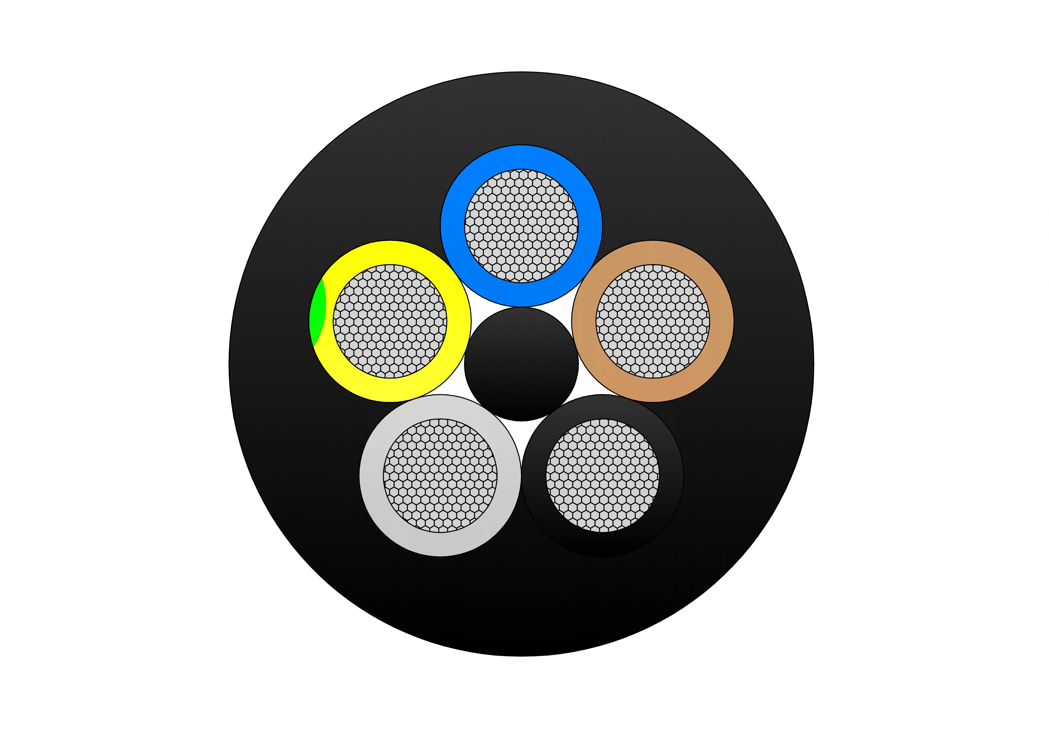
Phase Conductor
Class 5 tinned copper
Insulation
HEPR (Hard Ethylene Propylene Rubber)
Protective Earth Conductor
Individual copper wire braid
Central Filler
Rubber compound on a polyester textile support
Inner Sheath
PVC (Polyvinyl Chloride)
Armour
Steel wire braid over the inner sheath
Outer Sheath
PVC (Polyvinyl Chloride)
Sheath Colour
Red
Manufacturer Standard
IEC 60502-2, IEC 60228
Flame Retardant
IEC/EN 60332-1-2
Control Conductor
Class 5 tinned copper conductor
Semi-Conductive Layers
Semi-conductive tape over the conductor and inner and outer
semi-conductive rubber layer on the insulation
semi-conductive rubber layer on the insulation
Application
FG7H1OAR - 3.6/6kV, 6/10kV, 8.7/15kV and 12/20kV Cable is used for medium-voltage energy supply to equipment in tunneling and underground mining operations. It is suitable for both indoor and outdoor fixed installations under demanding conditions.
Technical Specifications
FG7H1OAR - 3.6/6kV, 6/10kV, 8.7/15kV and 12/20kV Cable
FG7H1OAR 3.6/6kV Cable
FG7H1OAR 6/10kV Cable
FG7H1OAR 8.7/15kV Cable
FG7H1OAR 12/20kV Cable
|
No. Of Cores |
Nominal Cross Sectional Area mm² |
CONDUCTOR DIAMETER |
MINIMUM OVERALL DIAMETER |
MAXIMUM OVERALL DIAMETER |
MAXIMUM TENSILE LOAD |
NOMINAL WEIGHT |
|
|
Phase Conductor |
Earth Conductor |
mm | mm | mm | N | kg/km | |
| 3+3 | 25 | 2.5ST | 6.1 | 36.3 | 40.2 | 1125 | 2250 |
| 3+3 | 35 | 2.5ST | 7.2 | 38.8 | 43.0 | 1575 | 3200 |
| 3+3 | 50 | 2.5ST | 8.9 | 42.5 | 47.0 | 2250 | 3860 |
| 3+3 | 70 | 2.5ST | 10.6 | 46.1 | 50.8 | 3150 | 4630 |
| 3+3 | 95 | 2.5ST | 12.3 | 49.9 | 55.0 | 4275 | 5680 |
| 3+3 | 120 | 2.5ST | 13.8 | 56.8 | 62.5 | 5400 | 7010 |
| 3+3 | 150 | 2.5ST | 15.5 | 57.8 | 63.5 | 6750 | 7910 |
| 3+3 | 185 | 2.5ST | 17.0 | 61.2 | 67.1 | 8225 | 9060 |
|
No. Of Cores |
Nominal Cross Sectional Area mm² |
CONDUCTOR DIAMETER |
MINIMUM OVERALL DIAMETER |
MAXIMUM OVERALL DIAMETER |
MAXIMUM TENSILE LOAD |
NOMINAL WEIGHT |
|
|
Phase Conductor |
Earth Conductor |
mm | mm | mm | N | kg/km | |
| 3+3 | 25 | 2.5ST | 6.1 | 36.3 | 40.8 | 1125 | 2290 |
| 3+3 | 35 | 2.5ST | 7.2 | 38.8 | 43.6 | 1575 | 3240 |
| 3+3 | 50 | 2.5ST | 8.9 | 42.5 | 47.6 | 2250 | 3900 |
| 3+3 | 70 | 2.5ST | 10.6 | 46.1 | 51.4 | 3150 | 4670 |
| 3+3 | 95 | 2.5ST | 12.3 | 49.9 | 55.6 | 4275 | 5720 |
| 3+3 | 120 | 2.5ST | 13.8 | 56.8 | 63.2 | 5400 | 7050 |
| 3+3 | 150 | 2.5ST | 15.5 | 57.8 | 64.2 | 6750 | 7950 |
| 3+3 | 185 | 2.5ST | 17.0 | 61.2 | 67.8 | 8225 | 9100 |
|
No. Of Cores |
Nominal Cross Sectional Area mm² |
CONDUCTOR DIAMETER |
MINIMUM OVERALL DIAMETER |
MAXIMUM OVERALL DIAMETER |
MAXIMUM TENSILE LOAD |
NOMINAL WEIGHT |
|
|
Phase Conductor |
Earth Conductor |
mm | mm | mm | N | kg/km | |
| 3+3 | 25 | 2.5ST | 6.1 | 40.9 | 45.2 | 1125 | 3040 |
| 3+3 | 35 | 2.5ST | 7.2 | 42.9 | 47.4 | 1575 | 3470 |
| 3+3 | 50 | 2.5ST | 8.9 | 46.9 | 51.8 | 2250 | 4280 |
| 3+3 | 70 | 2.5ST | 10.6 | 51.5 | 56.7 | 3150 | 5390 |
| 3+3 | 95 | 2.5ST | 12.3 | 55.2 | 60.7 | 4275 | 6420 |
| 3+3 | 120 | 2.5ST | 13.8 | 57.1 | 62.8 | 5400 | 7120 |
| 3+3 | 150 | 2.5ST | 15.5 | 62.1 | 68.2 | 6750 | 8600 |
|
No. Of Cores |
Nominal Cross Sectional Area mm² |
CONDUCTOR DIAMETER |
MINIMUM OVERALL DIAMETER |
MAXIMUM OVERALL DIAMETER |
MAXIMUM TENSILE LOAD |
NOMINAL WEIGHT |
|
|
Phase Conductor |
Earth Conductor |
mm | mm | mm | N | kg/km | |
| 3+3 | 25 | 2.5ST | 6.1 | 43.8 | 48.4 | 1125 | 3410 |
| 3+3 | 35 | 2.5ST | 7.2 | 45.7 | 50.4 | 1575 | 3830 |
| 3+3 | 50 | 2.5ST | 8.9 | 49.3 | 54.4 | 2250 | 4570 |
| 3+3 | 70 | 2.5ST | 10.6 | 54.1 | 59.6 | 3150 | 5760 |
| 3+3 | 95 | 2.5ST | 12.3 | 57.8 | 63.5 | 4275 | 6890 |
| 3+3 | 120 | 2.5ST | 13.8 | 61.0 | 66.9 | 5400 | 7650 |
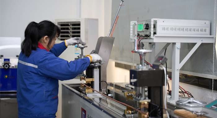
Quality Control
FG7H1OAR - 3.6/6kV, 6/10kV, 8.7/15kV and 12/20kV Cable
Raw Material Test
Raw Material Test for FG7H1OAR - 3.6/6kV, 6/10kV, 8.7/15kV and 12/20kV Cable ensures premium materials for medium-voltage performance. The structured process includes: Supplier Certification Review: Verify copper/aluminum conductors meet IEC 60228 class 2 for purity (>99.9% Cu or Al), stranding, and conductivity; XLPE insulation compound certified to IEC 60502-2 for electrical and mechanical properties. Conductor Analysis: Test copper/aluminum for tensile strength (>200 MPa Cu / >80 MPa Al), elongation (>10–15%), conductivity (≥97% IACS Cu / ≥61% IACS Al), and surface quality (no oxidation/cracks).Semi-Conductive Compound Testing: Semi-conductive screens evaluated for resistivity (≤1000 Ω·m), adhesion to conductor/insulation, and thermal stability.
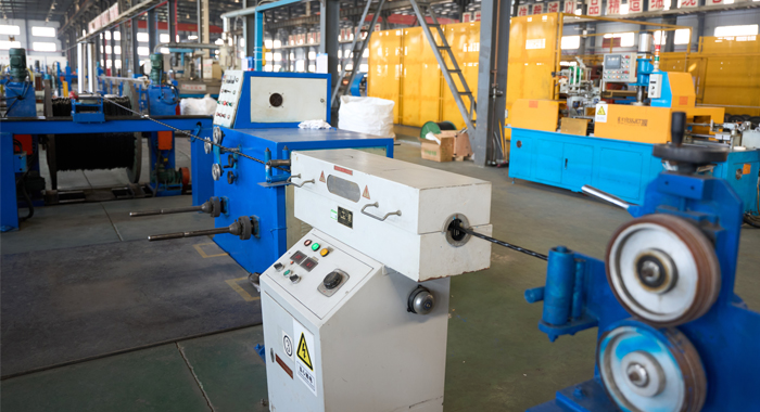
Process inspection
Process Inspection during manufacturing of FG7H1OAR - 3.6/6kV, 6/10kV, 8.7/15kV and 12/20kV Cable maintains precision for MV safety. Steps include: Conductor Stranding: Monitor class 2 stranding for uniform lay length, compactness, and no loose strands. Semi-Conductive & Insulation Extrusion: Apply conductor screen, XLPE insulation, and insulation screen in triple extrusion; inline diameter scanners, eccentricity monitors, and spark testers detect voids/defects.Screening Application: Apply copper tape/wire screen with precise overlap/coverage for effective grounding.Armor & Outer Sheath Extrusion: Add armor (if specified) and extrude outer sheath; real-time checks on thickness, adhesion, and surface quality. Continuous Monitoring: Track conductor resistance, insulation integrity, screen continuity, overall diameter, and voltage-specific parameters throughout.
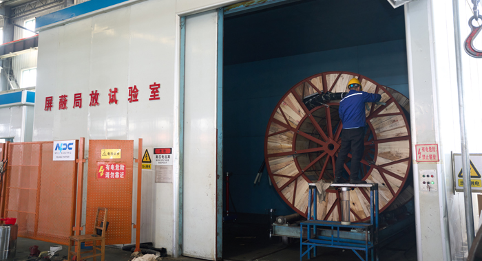
Finished Product
Finished Product Test confirms the FG7H1OAR - 3.6/6kV, 6/10kV, 8.7/15kV, and 12/20kV Cable meets MV standards before shipment. The procedure includes: Visual & Dimensional Inspection: Examine full length for defects, uniformity, markings, and measure outer diameter/weight per meter. Electrical Tests: DC resistance, insulation resistance (>1000 MΩ·km), high-voltage withstand (e.g., 11kV for 3.6/6kV, 17kV for 6/10kV, 24kV for 8.7/15kV, 29kV for 12/20kV/5 min), partial discharge (<5 pC), and screen continuity per IEC 60502-2. Mechanical Evaluation: Bending radius (12–15× OD), tensile strength, crush resistance, and armor integrity (if armored). Sheath & Insulation Performance: Thermal aging (135°C/168h), hot set test, oil/chemical resistance, and flame retardancy (if required) verified.
Application
The FG7H1OAR - 3.6/6kV, 6/10kV, 8.7/15kV and 12/20kV Cable is perfect for fixed underground power distribution in mining, industrial plants, substations, petrochemical facilities, renewable energy projects, and urban infrastructure requiring XLPE-insulated MV cable with high mechanical protection and reliable long-term operation.


Technical Advantages
● 30+ years of manufacturing experience
● ISO and UL certified production
● Customized cable and transformer solutions


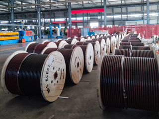
Product Packaging
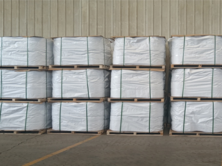
Wires and Cables packaging (1)
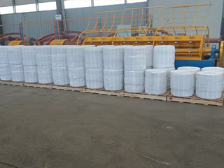
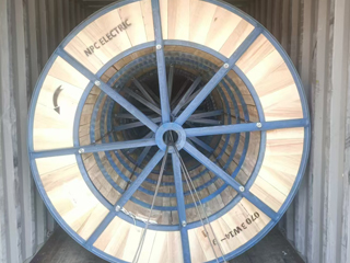
Wires and Cables packaging (2)
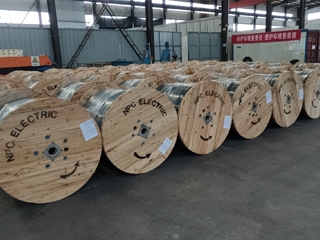
Wires and Cables packaging (3)
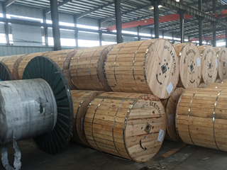
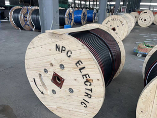
Wires and Cables packaging (4)
Wires and Cables packaging (5)
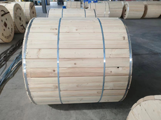
Wires and Cables packaging (6)
Wires and Cables packaging (7)
Wires and Cables packaging (8)
Related Products
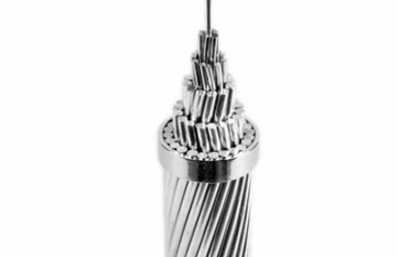
336.4 MCM Tulip AAC Cable
The 336.4 MCM Tulip AAC Cable is a high-performance All Aluminum Conductor designed for demanding overhead power transmission and distribution lines. Manufactured with 19 strands of premium 1350-H19 aluminum wire in a concentric lay configuration, this bare conductor provides excellent electrical conductivity with a low DC resistance of 0.0514 ohms per 1000 ft at 20°C. Featuring an overall diameter of 0.666 inches and a rated breaking strength of 6,150 lbs, the Tulip AAC delivers a robust ampacity of 513 amps while weighing only 315.8 lbs per 1000 ft. Its optimized strength-to-weight ratio minimizes sag and structural loading. Fully compliant with ASTM B-230 and B-231 standards, the 336.4 MCM Tulip AAC Cable offers outstanding corrosion resistance for long-term durability in harsh outdoor environments, making it the preferred choice for utility networks requiring cost-effective, high-reliability bare aluminum conductors.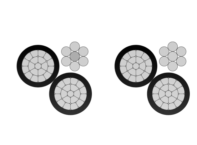
4/0 Lepas Aluminum Conductor Triplex Overhead Service Drop Cable
The 4/0-4/0-4/0 Lepas Aluminum Conductor Triplex Overhead Service Drop Cable is engineered for high-performance overhead power distribution from utility poles to residential, commercial, or light industrial weatherheads. It features concentric-lay-stranded 1350-H19 aluminum conductors (#4/0 AWG, 19-strand), black cross-linked polyethylene (XLPE) insulation for superior weather, UV, and thermal resistance, and a bare neutral messenger (#4/0 AWG, typically ACSR or AAAC 6201 alloy) for mechanical support and conductivity. Rated for 600 volts phase-to-phase at conductor temperatures up to 90°C (XLPE) or 75°C (Poly), it delivers an allowable ampacity of approximately 315 amps (XLP). Compliant with ASTM B-230, B-231, B-232, B-399, and ICEA S-76-474 standards, this robust, lightweight cable ensures easy installation, excellent electrical efficiency, and long-term durability in harsh outdoor environments, including wind, ice, moisture, and temperature extremes.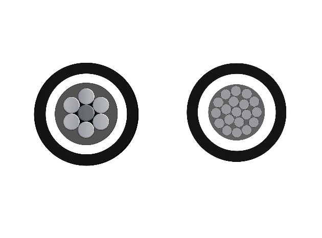
3-Layer 35kV AAC/AAAC/ACSR Tree Wire - Covered Overhead MV Cable
The 3-Layer 35kV AAC/AAAC/ACSR Tree Wire is an advanced covered medium-voltage overhead conductor engineered for reliable performance in areas with dense vegetation. It features a concentrically stranded AAC, AAAC, or ACSR conductor protected by a triple-layer system of track-resistant high-density polyethylene (HDPE) or cross-linked polyethylene (XLPE). The multi-layer covering provides exceptional tracking resistance, abrasion protection, and weatherability while significantly reducing the risk of electrical faults caused by tree limb contact and minimizing wildfire ignition potential. This design allows closer spacing to vegetation and lowers vegetation management costs. Suitable for both conventional overhead lines and spacer cable systems, the 3-Layer 35kV AAC/AAAC/ACSR Tree Wire meets ICEA S-121-733 and related ASTM standards. It undergoes rigorous quality testing from raw materials to finished product, ensuring excellent dielectric strength, mechanical robustness, and long-term durability in challenging environments.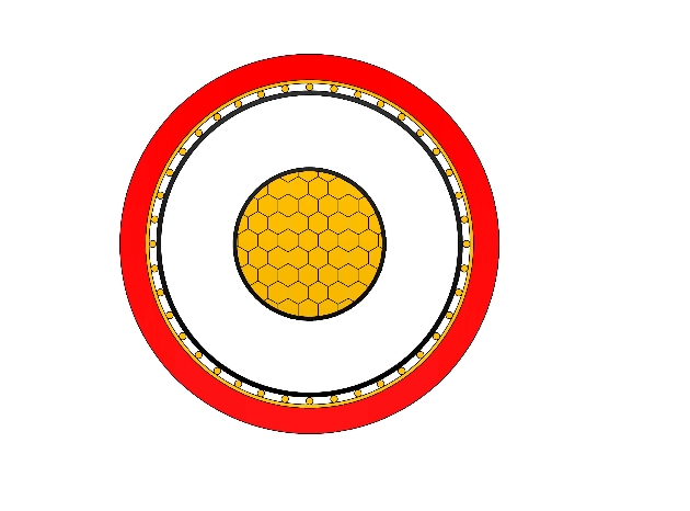
N2XSY Medium Voltage Power Cable(6/10kV, 12/20kV, 18/30kV)
N2XSY are medium voltage power cables with copper conductors and cross-linked polyethylene (XLPE) insulation, designed according to DIN VDE 0276-620 standards. Constructed with high-purity copper conductors, thermosetting XLPE insulation, metallic screen (copper tape or wires), and tough PVC outer sheath, it meets IEC 60502-2 requirements. The screen ensures electromagnetic compatibility and fault protection. Low tan delta, high breakdown strength, and excellent thermal endurance minimize losses and support overloads. PVC sheath provides solid mechanical and moisture protection for fixed installations. Optional longitudinal water-blocking improves performance in damp areas. Flame-retardant and easy to handle, the N2XSY Medium Voltage Power Cable is favored for power grids, manufacturing plants, commercial developments, and renewable energy sites demanding robust single-core medium voltage cabling with proven durability and cost efficiency in buried or tray installations worldwide.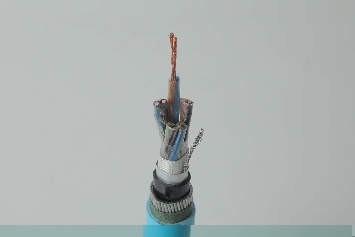
Instrumentation Cables—XLPE Insulated,Individual &Overall Screened,Unarmoured PVC Sheathed Cables(CU/XLPE/IOSCR/PVC)
Instrumentation Cables are multi-conductor cables that carry and transport low-voltage electrical signals. These low-voltage signals are used to control and monitor electrical power systems. Instrumentation cables have many different industrial applications that include broadcasting, equipment control, such as drilling and pumping in the oil and gas industry, and data transfer, which includes analog and digital signals. They are manufactured according to the BS EN 50288-7 and BS EN 50288-1 standards to ensure quality. Depending on the application, instrumentation cables can be insulated with PVC or XLPE; the cables can be armoured or unarmoured. The sheathing materials can be of PVC, LSZH, or PE. The cables can have additional flame retardant or flame retardant properties, and they can be manufactured with special protections such as lead sheaths, or DRYLAM or AIRBAG technology.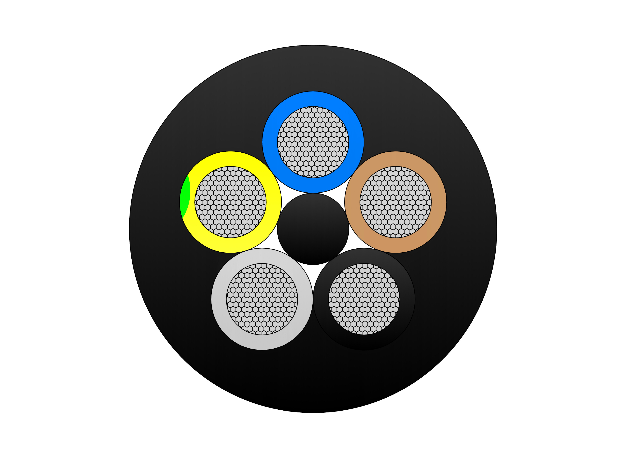
Type 450 Flexible Copper Screened Mining Cable With Two Earth And One Pilot Core
The Type 450 Flexible Copper Screened Mining Cable is a medium-voltage, heavy-duty mining cable designed for power supply in draglines, slow reeling, and industrial applications requiring two earth cores and one pilot core. It features tinned annealed copper conductors, EPR (XR-EP-90) insulation, and a tinned copper/polyamide braid screen for electrical shielding. The double-layer HD-PCP sheath provides extra heavy-duty protection, including oil resistance, flame retardancy, and chemical durability. Available in voltage ratings from 3.3kV to 33kV, the cable meets AS/NZS 2802 and related standards, ensuring high performance and reliability in harsh mining environments.FAQ From Customers
-
What are the advantages of power cables and overhead lines?(1) Reliable operation, because it is installed in a hidden place such as underground, it is less damaged by external forces, has less chance of failure, and the power supply is safe, and it will not cause harm to people; (2) The maintenance workload is small and frequent inspections are not required; (3) No need to erect towers; (4) Help improve power factor.
-
Which aspects should be considered when choosing the cross section of a power cable?(1) The long-term allowable working current of the cable; (2) Thermal stability once short circuited; (3) The voltage drop on the line cannot exceed the allowable working range.
-
What are the measures for cable fire prevention?(1) Use flame-retardant cables; (2) Use fireproof cable tray; (3) Use fireproof paint; (4) Fire partition walls and fire baffles are installed at cable tunnels, mezzanine exits, etc.; (5) Overhead cables should avoid oil pipelines and explosion-proof doors, otherwise local pipes or heat insulation and fire prevention measures should be taken.
-
What should be paid attention to during the transportation and handling of cables?(1) During transportation, loading and unloading, cables and cable reels should not be damaged. It is strictly forbidden to push the cable reels directly from the vehicle. Generally, cables should not be transported and stored flat. (2) Before transporting or rolling the cable reel, ensure that the cable reel is firm, the cable is wound tightly, the oil pipe between the oil-filled cable and the pressure oil tank should be fixed without damage, the pressure oil tank should be firm, and the pressure indication should meet the requirements.
-
What inspections should be carried out for the acceptance of cable lines?(1) The cable specifications should meet the regulations, the arrangement should be neat, no damage, and the signs should be complete, correct and clear; (2) The fixed bending radius of the cable, the related distance and the wiring of the metal sheath of the single-core power cable should meet the requirements; (3) The cable terminal and the middle head should not leak oil, and the installation should be firm. The oil pressure of the oil-filled cable and the meter setting should meet the requirements; (4) Good grounding; (5) The color of the cable terminal is correct, and the metal parts such as the bracket are completely painted; (6) There should be no debris in the cable trench, tunnel, and bridge, and the cover should be complete.
Welcome your inquiry
Honesty, Integrity, Frugality, Activeness and Passion