Isolation Transformer vs Normal Transformer: Key Differences Explained
2026-06-26
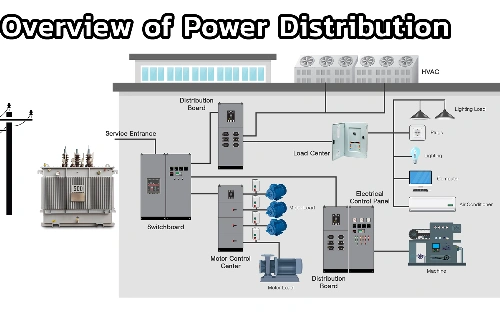
Introduction to Transformers in Modern Power Systems
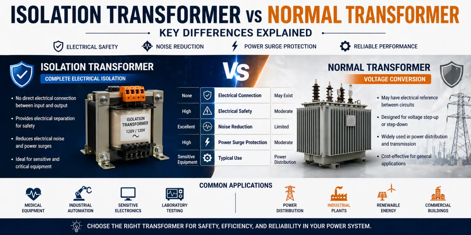
Transformers are fundamental components in electrical engineering, relying on the principle of electromagnetic induction to transfer energy between circuits. A standard electrical transformer, often called a power transformer, steps voltage up or down to match system requirements while maintaining efficient power delivery. In contrast, an isolation transformer emphasizes complete electrical separation between its primary and secondary windings.
From a practical working perspective, engineers select transformers based on application demands such as voltage conversion, safety compliance, noise immunity, and fault tolerance. In today's interconnected power systems—ranging from industrial automation to healthcare facilities—understanding these distinctions ensures reliable operation, regulatory adherence (like IEC and UL standards for medical devices), and minimized downtime. Isolation transformers, particularly isolation transformer 120v models common in North American setups, play a vital role where human safety or equipment protection is paramount.
Fundamental Working Principle – Electromagnetic Induction in Both Types
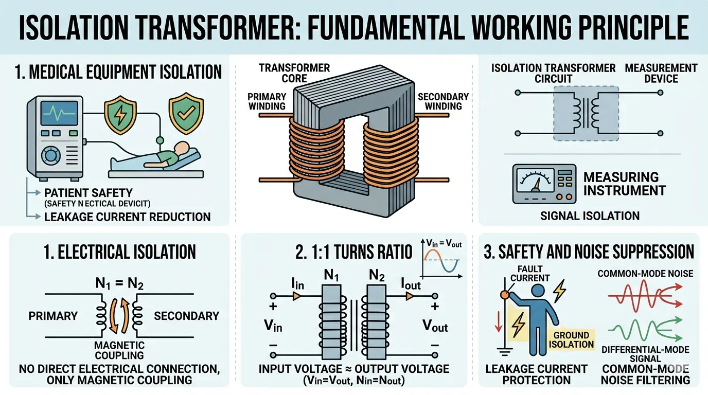
Both isolation transformers and regular transformers operate on Faraday's law of electromagnetic induction. Alternating current in the primary winding generates a varying magnetic flux in the shared core, typically constructed from laminated silicon steel to reduce eddy current and hysteresis losses. This flux induces a voltage in the secondary winding proportional to the turns ratio (N_secondary / N_primary).
In a normal power transformer, the primary and secondary windings share a common magnetic path, and while there is no direct conductive link in double-wound designs, the focus remains on efficient voltage transformation with minimal losses. Engineers calculate core saturation (B_max), winding resistance, and leakage inductance to optimize efficiency, often exceeding 95-98% in large units.
For isolation transformers, the same induction principle applies, but design prioritizes maximizing physical and dielectric separation. Windings are often placed in separate compartments or with enhanced insulation barriers, including a Faraday shield (electrostatic screen) grounded to divert capacitive coupling currents. This reduces common-mode noise transfer. In real-world testing, engineers measure inter-winding capacitance, which is significantly lower in isolation designs (pF range) compared to standard transformers. The result is true galvanic isolation—no DC path exists between input and output circuits.
From an operational viewpoint, this shared principle means both types handle AC power at line frequencies (50/60 Hz), but isolation transformers maintain waveform integrity better under noisy conditions.
Structural Design Differences – Primary and Secondary Windings Configuration
The physical construction reveals the most significant divergence. In a regular transformer, primary and secondary windings may be layered concentrically on the same bobbin for compactness and better magnetic coupling, reducing leakage flux. This design favors cost and size efficiency in power distribution applications where voltage step-up or step-down is the goal.
Isolation transformers, however, employ separated winding techniques—often side-by-side or with substantial physical barriers—to achieve high dielectric strength (thousands of volts isolation rating). A key feature is the optional electrostatic shield between windings, which intercepts capacitive currents and routes them to ground, preventing noise propagation. Modern designs incorporate advanced insulation materials like Nomex or epoxy impregnation to withstand higher hipot test voltages.
In practice, engineers specify isolation transformers with a 1:1 turns ratio for applications needing no voltage change, such as isolation transformer 120V units that deliver 120V output from 120V input while breaking ground loops. Regular transformers rarely prioritize this; their ratios are tailored for conversion (e.g., 480V to 208V). Field data shows isolation designs are bulkier and heavier due to extra insulation and core material, but offer superior transient withstand capability.
This structural rigor directly impacts thermal management: isolation units often run cooler under no-load due to reduced parasitic currents.
The structural distinctions become evident when examining the following comparison:
Table 1:Design and Construction Comparison
|
Parameter |
Normal / Power Transformer |
Isolation Transformer |
|
Primary-Secondary Connection |
Magnetic coupling only (no direct electrical in double-wound) |
Full galvanic isolation with enhanced dielectric barriers |
|
Turns Ratio |
Variable (step-up or step-down, e.g., 2:1, 1:2) |
Typically 1:1 (isolation transformer 120v models maintain equal voltage) |
|
Winding Configuration |
Often concentric layers for tight coupling |
Side-by-side or compartmentalized with physical separation |
|
Electrostatic Shield (Faraday Shield) |
Rarely present |
Commonly included and grounded to reduce capacitive coupling |
|
Inter-winding Capacitance |
Higher (typically 100–500 pF) |
Significantly lower (typically <50 pF) |
|
Typical Core Type |
Laminated silicon steel |
Laminated or toroidal with advanced insulation |
|
Dielectric Strength (Hipot Test) |
Standard (1–2 kV) |
High (4 kV or higher for reinforced insulation) |
Electrical Isolation and Safety – Breaking Conductive Paths
Electrical isolation defines the isolation transformer. There is no electrical connection between input and output circuits; energy transfers solely via magnetic fields. This galvanic isolation protects against ground faults, where a fault on the secondary side does not energize the primary ground, reducing shock hazards.
In contrast, a normal transformer, even double-wound, may allow indirect coupling through shared grounds or higher capacitive leakage, potentially propagating faults. From a working angle, electricians and maintenance teams value isolation transformers in scenarios involving patient contact or sensitive electronics. Leakage current is minimized to microamp levels, complying with medical standards like IEC 60601.
Practical testing involves applying high voltage between windings and measuring leakage. Isolation transformers routinely pass 4kV or higher tests. In power surges, the isolation prevents surge energy from jumping circuits directly, though suppression devices are still recommended. Regular transformers offer basic transformation but lack this robust barrier, making them less suitable for high-risk environments.
Engineers note that while both provide some separation, only designed isolation transformers guarantee "electrical separation transformer" performance under fault conditions.
Performance in Power Surges and Noise Suppression
Power surges and electromagnetic interference (EMI/RFI) challenge modern systems. A regular power transformer passes differential-mode noise relatively easily due to tighter coupling. Isolation transformers excel here because of the Faraday shield and physical separation, attenuating common-mode noise by 60-100 dB depending on frequency.
In real installations, such as data centers or laboratories, engineers observe reduced equipment malfunctions when deploying power isolation transformers. Surges induced on the primary are not conductively transferred; the magnetic core saturates or dissipates energy differently. For isolation transformer 120v models, this protection is critical in residential or light commercial setups with variable loads.
Quantitative analysis in design labs uses oscilloscopes to compare before/after waveforms. Isolation units demonstrate cleaner output sine waves under distorted input conditions. Regular transformers, optimized for efficiency, may introduce more harmonics or allow ground loops that amplify noise in audio, medical imaging, or control systems.
This makes isolation transformers preferable in environments with frequent switching loads or nearby lightning-prone areas.
From a practical engineering and safety compliance perspective, the performance differences are quantified in the table below:
Table 2:Electrical Performance and Safety Parameters
|
Parameter |
Normal / Power Transformer |
Isolation Transformer (incl. Medical Grade) |
|
Galvanic Isolation |
Limited (possible indirect coupling via ground) |
Complete (no DC conductive path between input and output circuits) |
|
Leakage Current (Primary to Secondary) |
Typically 0.5–5 mA |
Very low (<100 µA normal, <50 µA for medical models) |
|
Common-Mode Noise Rejection |
Moderate (20–40 dB) |
Excellent (60–100 dB with Faraday shield) |
|
Surge Protection Capability |
Basic voltage transformation only |
Superior transient isolation and suppression support |
|
Patient/Operator Safety (Medical) |
Not certified for direct patient contact |
Compliant with IEC 60601 / UL 60601 (patient leakage ≤100 µA) |
|
Isolation Voltage Rating |
1–2.5 kV typical |
4 kV+ (reinforced/double insulation) |
Applications in Medical Equipment and Sensitive Systems
Medical equipment demands the highest safety margins. Medical isolation transformers provide electrical separation to limit patient leakage current, even if internal faults occur. Devices like ECG monitors, anesthesia machines, and imaging systems use these to float the secondary circuit, ensuring no path for fault current through the patient.
From a design engineer's perspective, compliance testing includes creepage and clearance distances per safety standards. Isolation transformers here often feature low-leakage designs and toroidal cores for reduced stray fields. Regular transformers lack the certified isolation levels needed, risking non-compliance or equipment damage during power events.
Beyond medicine, marine, industrial control, and telecommunications applications leverage isolation for similar reasons—preventing corrosion from stray currents or protecting PLCs from ground potential differences. In contrast, standard power transformers dominate utility-scale voltage conversion where safety isolation is secondary to efficiency and cost.
Real-world case studies show fewer downtime incidents in hospitals using dedicated power isolation transformer setups.
Efficiency, Cost, and Operational Trade-offs
Efficiency comparisons require nuance. Regular transformers achieve higher peak efficiencies in voltage-conversion roles due to optimized coupling and lower material use. Isolation transformers may exhibit slightly lower efficiency (1-3% difference) because of added insulation and shielding, which increase resistance or core losses marginally. However, in no-load or light-load scenarios common in standby medical systems, isolation designs can prove more energy-efficient by eliminating ground loop currents.
Cost-wise, isolation transformers are more expensive due to specialized construction, higher-grade materials, and rigorous testing. From procurement and installation viewpoints, engineers weigh total ownership cost: isolation units reduce maintenance from surge-related failures and extend equipment life.
In field operations, size and weight matter—toroidal isolation transformers offer compact, low-noise alternatives to traditional laminated cores. Selection involves load calculations, inrush current handling, and environmental factors like temperature rise (typically Class B or F insulation).
To support real-world selection and operational decision-making, consider the following operational comparison:
Table 3:Application and Operational Characteristics
|
Parameter |
Normal / Power Transformer |
Isolation Transformer |
|
Primary Purpose |
Voltage step-up/step-down in power distribution |
Electrical separation, noise reduction, and safety |
|
Typical Efficiency (Full Load) |
95–98% |
92–96% (slightly lower due to extra insulation) |
|
Relative Cost |
Lower (optimized for material efficiency) |
1.5–3× higher (due to shielding and testing) |
|
Size & Weight (for same kVA) |
More compact |
Larger and heavier (extra barriers and core material) |
|
Key Applications |
Utility grid, industrial power conversion |
Medical equipment, sensitive electronics, labs, and marine systems |
|
Noise & EMI Performance |
Standard |
Superior (reduces the impact of ground loops and power surges) |
|
Maintenance Focus |
Voltage regulation and thermal management |
Insulation resistance, leakage current testing |
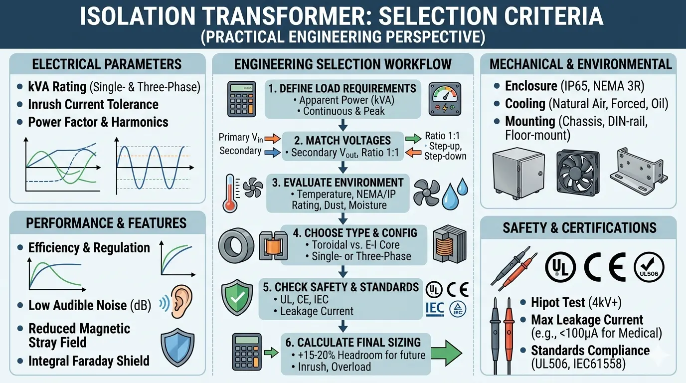
Selection Criteria from a Practical Engineering Perspective
Choosing between types starts with defining requirements: Is voltage transformation primary, or is safety isolation essential? For pure power delivery, select a standard electrical transformer sized for KVA rating with appropriate regulation. For sensitive loads, specify an isolation transformer with documented isolation voltage, shielding, and agency approvals.
Engineers perform site surveys for noise levels, ground integrity, and surge exposure. Modern design software simulates magnetic fields and thermal profiles. Installation best practices include proper grounding of the shield (if present) and avoiding secondary grounding in certain floating configurations. Maintenance involves insulation resistance testing (megger) and thermal imaging to detect hot spots early.
In international exports, compliance with regional standards (UL, CE, CSA) differentiates products. Isolation transformer 120V variants are popular for the US/Canada markets, while 230V equivalents serve Europe.
Conclusion – Choosing the Right Transformer for Safety and Reliability
The key differences between isolation transformers and normal (regular) transformers stem from purpose: voltage transformation versus electrical isolation. While both rely on electromagnetic induction and feature primary and secondary windings, isolation designs deliver galvanic separation, superior noise rejection, and enhanced protection against power surges—critical for medical equipment electrical separation and other high-stakes applications.
In practical engineering workflows, prioritizing isolation transformers where human safety or signal integrity matters yields long-term benefits despite higher upfront costs. As power systems evolve with renewables and sensitive electronics, understanding these distinctions empowers better system design and operational resilience.
Related Articles


Related Products
45kVA Three Phase Pad Mounted Transformer
The 45 kVA pad-mounted transformer meets ANSI, CSA, NEMA, IEEE, and DOE standards. The compartmental dead-front enclosure features tamper-resistant doors, mineral oil or ester fluid insulation, and ONAN cooling for a 65°C temperature rise, enabling quiet, overload-capable operation in outdoor pad installations.
4 Artemia Aluminum Conductor Triplex Overhead Service Drop Cable
The 4 Artemia Aluminum Conductor Triplex Overhead Service Drop Cable is engineered for superior performance in overhead power distribution systems. Featuring three aluminum conductors with a neutral messenger, this cable ensures efficient electricity transmission for residential, commercial, and light industrial applications. Its robust construction includes high-grade aluminum alloy for enhanced conductivity and corrosion resistance, wrapped in weatherproof insulation to withstand harsh environmental conditions like UV exposure, rain, and wind. With a 4 AWG size, it supports voltages up to 600V and offers low impedance for minimal power loss. Easy to install with standard overhead fittings, it complies with ASTM, ANSI, and ICEA standards for safety and reliability. This triplex design reduces sagging and improves longevity, making it a cost-effective choice for utility companies and contractors. Whether upgrading existing lines or new installations, the 4 Artemia delivers dependable service with minimal maintenance. Invest in quality that powers your world efficiently.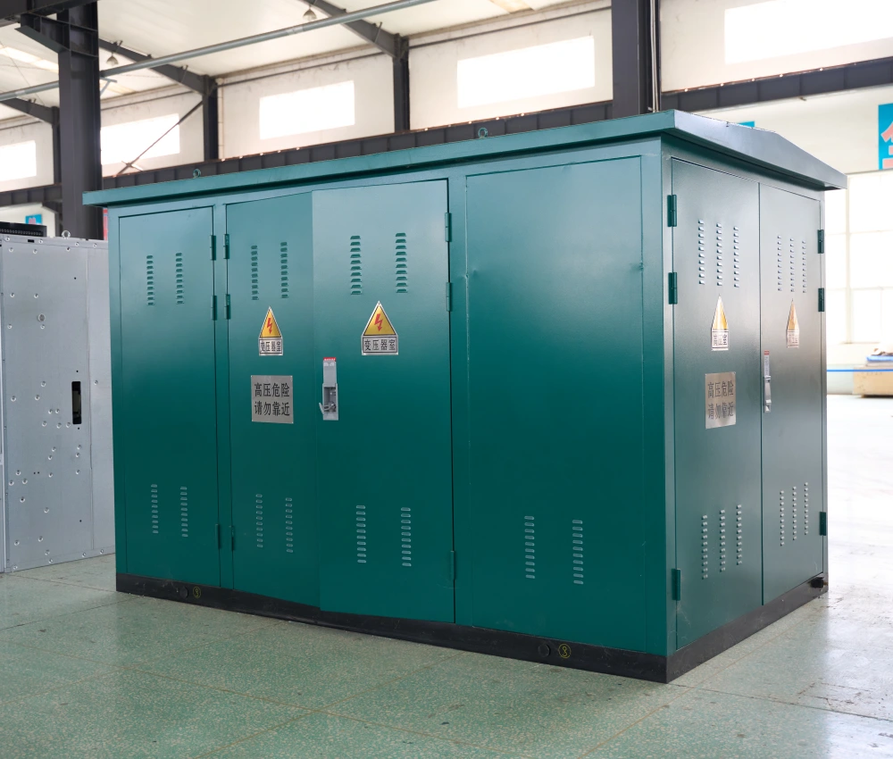
Prefabricated Compact Substation
The Prefabricated Compact Substation is an integrated medium-voltage and low-voltage power distribution solution engineered for modern urban infrastructure, renewable energy systems, industrial plants, and commercial facilities. The equipment combines medium-voltage switchgear, distribution transformer, and low-voltage distribution panel into a compact steel enclosure, significantly reducing installation time and site construction costs while improving operational reliability.Designed for outdoor operation under demanding environmental conditions, the compact substation features corrosion-resistant housing, advanced insulation systems, and optimized ventilation structures to ensure stable long-term performance. Its modular architecture allows flexible transformer capacities, voltage combinations, and protection configurations to meet different regional grid requirements and project specifications. The unit supports fast deployment, simplified maintenance, and enhanced safety protection, making it an ideal choice for power utilities, solar farms, wind power stations, transportation infrastructure, data centers, and residential developments. With intelligent monitoring options and customizable internal layouts, the prefabricated compact substation provides efficient, safe, and scalable electrical distribution for modern power networks.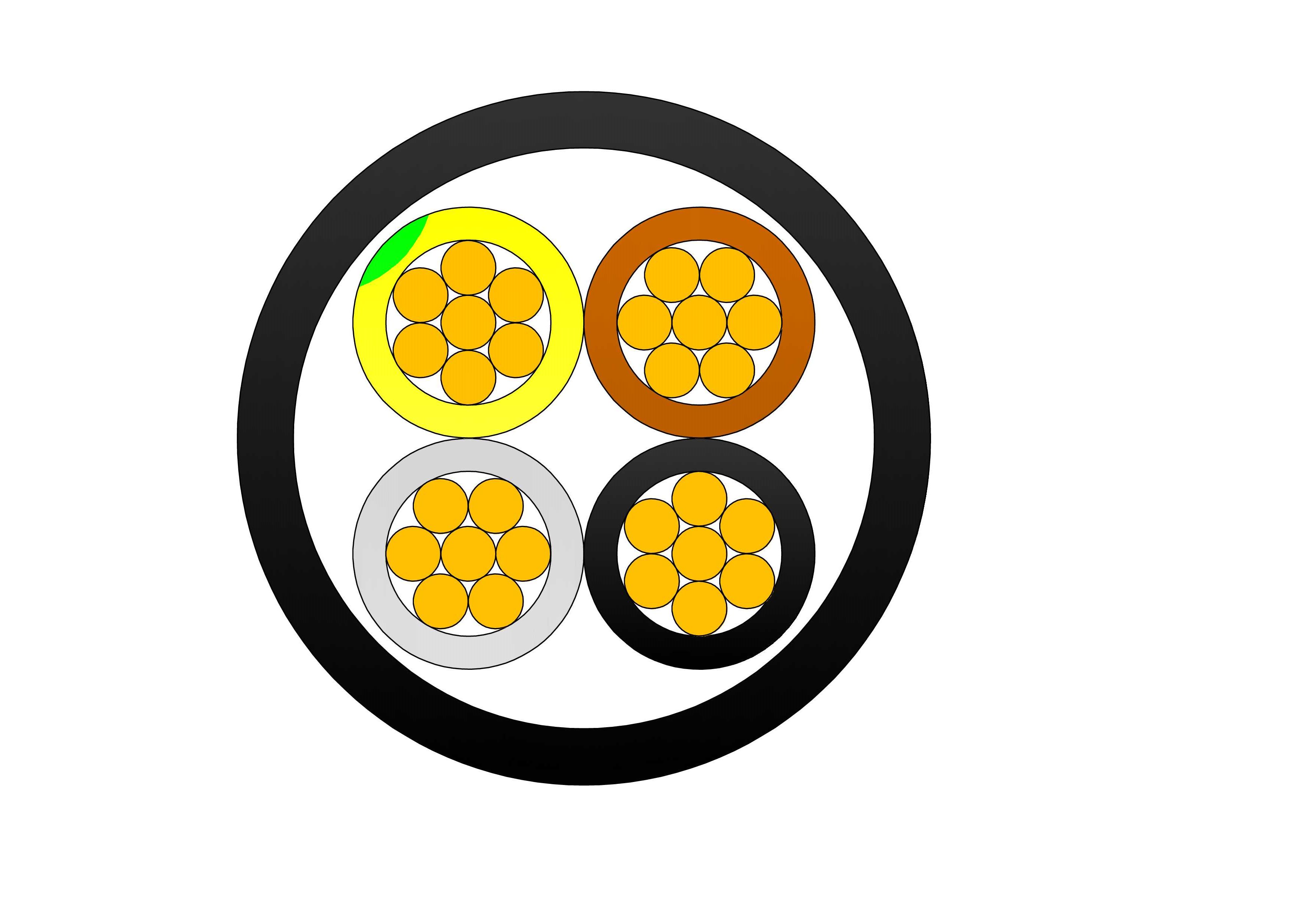
4/5 Cores SWA Armoured Cable
The 4/5 Cores SWA Armoured Cable is engineered for demanding power distribution applications where durability, safety, and mechanical protection are critical. Manufactured with premium copper or aluminum conductors, advanced XLPE insulation, galvanized steel wire armour, and a weather-resistant PVC outer sheath, the cable provides exceptional reliability in harsh operating environments. Its steel wire armour offers excellent protection against impact, tensile loads, crushing forces, and accidental mechanical damage. This makes the cable ideal for underground installations, cable trenches, and direct burial applications. The XLPE insulation delivers superior dielectric performance, low transmission losses, and thermal resistance up to 90°C continuous operation. The PVC outer sheath provides excellent resistance against moisture, chemicals, oils, abrasion, and UV radiation. Complying with IEC and BS standards, the cable is suitable for utility networks, industrial facilities, renewable energy projects, transportation infrastructure, and commercial developments. The 4/5 Cores SWA Armoured Cable offers an economical and dependable solution for modern power distribution systems.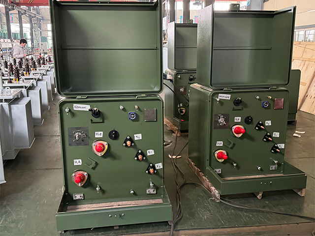
630kVA Single Phase Pad Mounted Transformer
Elevate your underground power distribution with the robust 630kVA Single Phase Pad Mounted Transformer, specifically designed for high-demand residential and commercial loop-feed networks. This oil-immersed, single-phase unit incorporates premium electrical steel laminations and heavy-duty windings to minimize energy losses and provide outstanding thermal performance under continuous loads. Meeting ANSI C57.12.38 and IEEE C57.12.90 standards, this 630kVA padmount transformer delivers precise voltage transformation from primary levels up to 34.5kV to common secondary voltages like 120/240V or 277/480V, supporting extended overloads and long-term reliability in densely populated areas.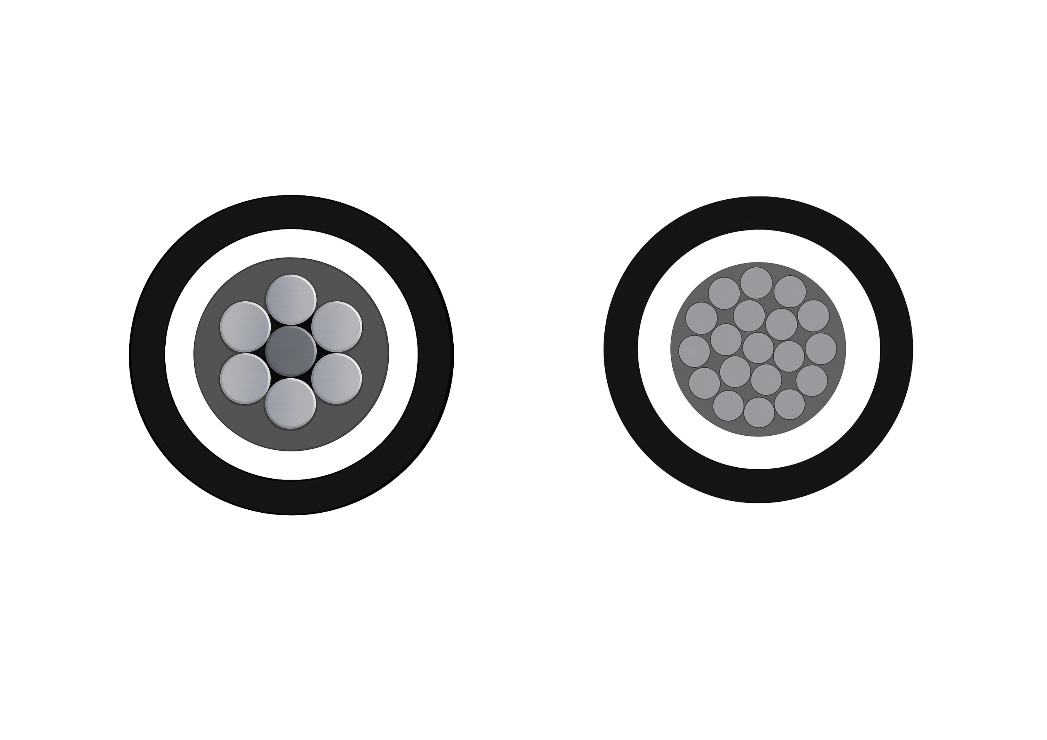
15kV 3-Layer AAAC/ACSR/AAC Tree Wire - Triple Layer Covered Conductor
The 3-Layer 15kV AAAC/ACSR/AAC Tree Wire is a specialized covered overhead conductor developed for distribution lines in areas with dense vegetation. It uses concentrically stranded AAAC, ACSR, or AAC conductors protected by a triple-layer system of track-resistant HDPE or XLPE. The multi-layer covering delivers exceptional tracking resistance, abrasion protection, and weatherability while greatly reducing the risk of electrical faults from tree limb contact and helping minimize wildfire ignition potential. This advanced design allows closer spacing to vegetation and lowers vegetation management costs. Suitable for conventional overhead or spacer cable systems, the 3-Layer 15kV AAAC/ACSR/AAC Tree Wire offers a cost-effective solution for improving line reliability. It complies with ICEA and ASTM standards and undergoes extensive quality testing to ensure long-term performance and safety.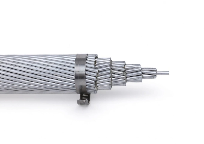
397.5 MCM Canna AAC Cable
The 397.5 MCM Canna AAC Cable represents premium All Aluminum Conductor technology for overhead power applications. Built with 19 strands of high-conductivity 1350-H19 aluminum, this bare conductor delivers an optimal balance of electrical efficiency and mechanical robustness. With a 0.724-inch diameter, 7,110 lbs breaking strength, and 570 amps ampacity, the Canna AAC offers low DC resistance of 0.0435 ohms per 1000 ft at 20°C and a weight of 373.2 lbs per 1000 ft. This design minimizes sag while providing excellent corrosion resistance for extended outdoor service. Manufactured to meet ASTM B-230 and B-231 standards, the 397.5 MCM Canna AAC Cable undergoes extensive quality testing from raw materials through finished product. It is the perfect solution for new installations and upgrades in transmission and distribution systems that demand lightweight, high-conductivity bare aluminum conductors.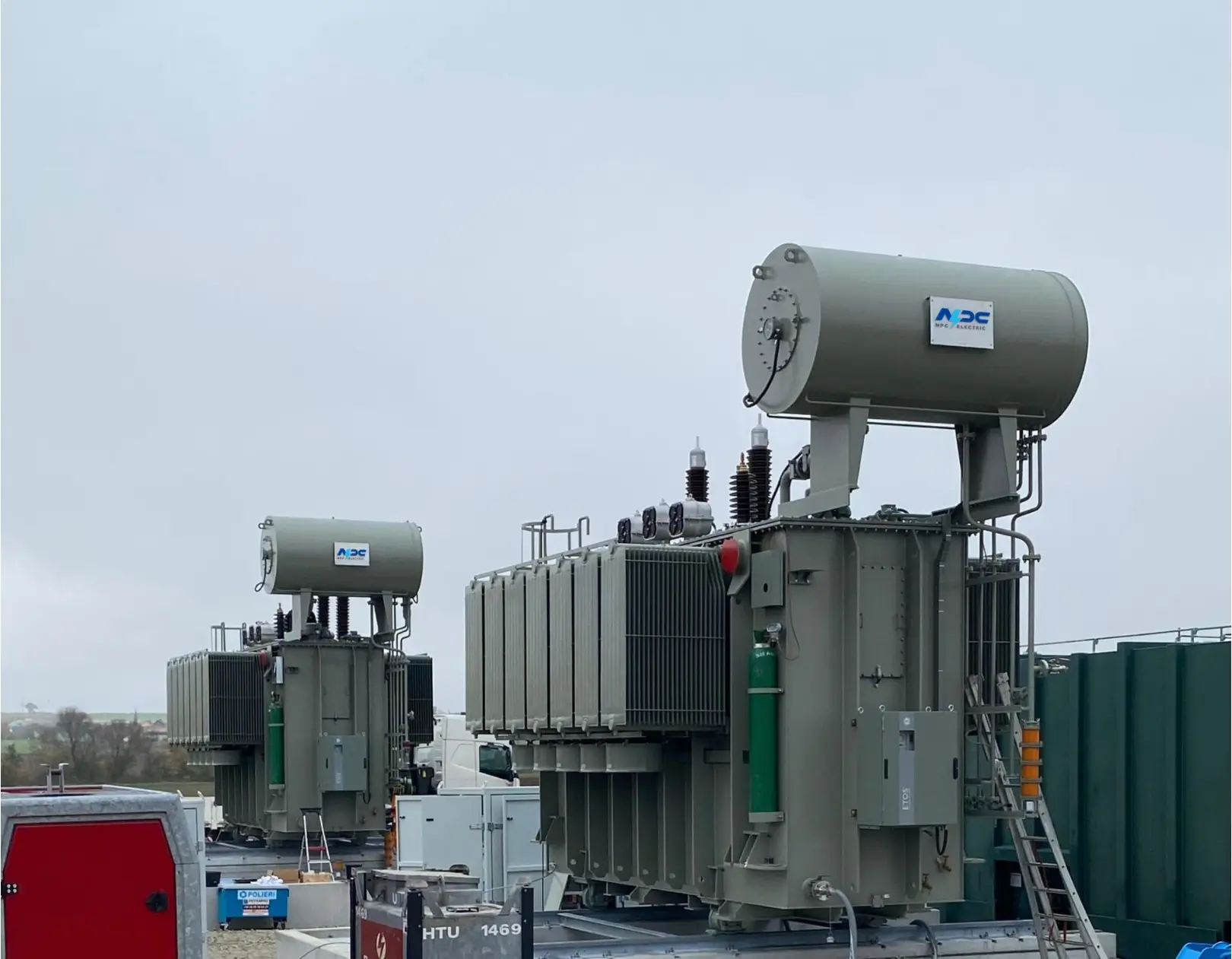
100kV 200kVA 250kVA 315kVA Three-Phase Oil-Immersed Substation Power Transformer
This 100kV three-phase oil-immersed substation power transformer is engineered for stable voltage transformation across 200kVA, 250kVA, and 315kVA capacity ranges. Designed for medium to high-voltage distribution networks, it delivers exceptional reliability, thermal endurance, and operational efficiency in substations, industrial plants, and utility distribution grids. The transformer utilizes high-grade insulation, precision-wound copper conductors, and robust core materials to ensure low losses, long service life, and consistent performance under demanding electrical and environmental conditions. Its sealed oil-immersed structure enhances insulation strength and optimizes heat dissipation for safe and continuous operation.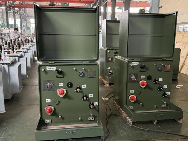
50kVA Conventional Type Single Phase Pole Mounted Transformer
The 50kVA Conventional Type Single Phase pole Mounted transformer produced by NPC ELECTRIC has a rated capacity ranging from 10kVA to 333kVA, meeting the standards of ANSI/IEEE C57, IEC60076, etc. Its main function is to convert high-voltage power (such as 10kV, 11kV, etc.) into low-voltage power (such as 220V, 240V) through the transformer for use in homes, shops, industrial equipment, etc. It is suitable for residential areas, commercial areas, rural power grids, agricultural facilities and small industrial power supply. Standard features encompass mineral oil insulation (ONAN cooling), aluminum or copper windings, primary voltages 2.4kV–34.5kV grounded wye or delta (common: 7200/12470GrdY, 7620/13200GrdY, 12470GrdY/7200, 24940GrdY/14400, 34500GrdY/19920), secondary 120/240V or 240/120V split-phase, BIL ratings 95–150kV HV / 30kV LV, impedance typically 2.0–4.0%, ±2×2.5% or 5-position tap changer, conventional or CSP (completely self-protected) configurations with internal fuses, lightning arresters, weak-link protection, pressure relief valve, oil sight gauge, and ANSI 70 gray tank finish. Efficiency typically reaches 99.11%+, with low sound levels and corrosion-resistant hardware for extended outdoor service.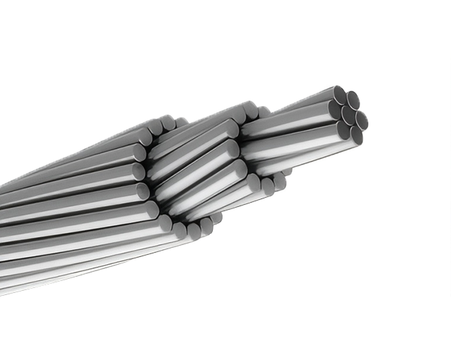
795 MCM DRAKE ACSR Conductor Cable
The ACSR CAA 795 MCM 26/7F DRAKE is a widely used, high-capacity overhead conductor designed for power transmission and distribution systems. It features a rugged construction of 26 hard-drawn 1350-H19 aluminium wires wrapped around 7 galvanized steel strands, forming a strong and conductive concentrically stranded cable. Built to ASTM B232 specifications, this conductor delivers excellent electrical performance, while its steel-reinforced core offers the mechanical strength needed for long-span installations. The steel strands are galvanized to Class A or B, providing reliable corrosion resistance in outdoor environments. With its proven design and high load-handling capabilities, the DRAKE configuration is commonly used across utility networks, particularly for high-voltage transmission lines where strength, conductivity, and longevity are critical. The aluminum 1350-H19 provides excellent corrosion resistance and low electrical resistance (0.0223 Ω/1000ft at 20°C), while the steel enhances sag control over long spans. Suitable for voltages up to 230kV in distribution lines, the 795 MCM Drake ACSR Conductor Cable minimizes line losses and withstands harsh weather, including wind and ice loading.
2/3/4 Cores Aluminum Cable AL/XLPE/PVC Low Voltage Power Cable
The 2/3/4 Cores Aluminum Cable AL/XLPE/PVC is designed for reliable low-voltage power transmission and distribution in industrial, commercial, and utility applications. Manufactured with high-conductivity stranded aluminum conductors, premium XLPE insulation, and a durable PVC outer sheath, the cable provides an economical alternative to copper cables while maintaining excellent electrical performance. The XLPE insulation offers outstanding dielectric strength, low insulation losses, and thermal stability, allowing continuous conductor operation at temperatures up to 90°C. The PVC sheath protects against moisture, abrasion, chemicals, UV exposure, and environmental stress, ensuring long-term durability in demanding installations. Available in 2-core, 3-core, and 4-core configurations, the cable is suitable for single-phase and three-phase power systems. Manufactured according to IEC 60502-1 standards, it ensures safe and efficient electrical distribution across a wide range of applications. Its lightweight construction reduces transportation and installation costs, making the 2/3/4 Cores Aluminum Cable AL/XLPE/PVC an ideal solution for power infrastructure, commercial facilities, industrial plants, and renewable energy projects.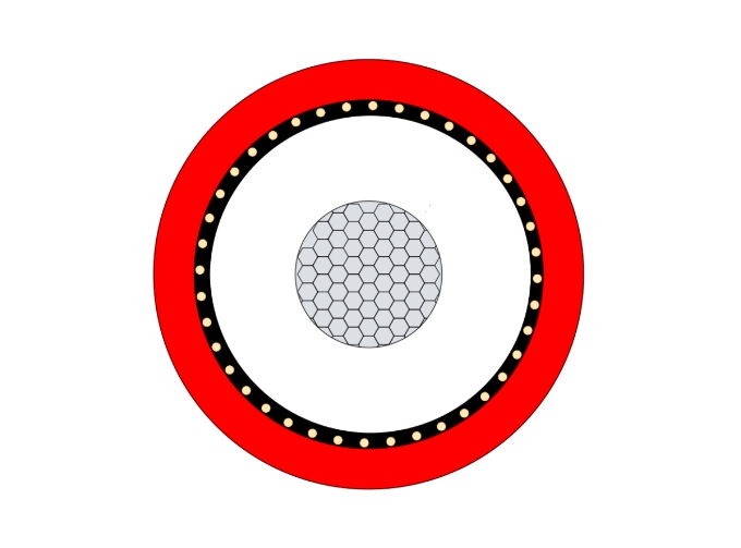
NA2XSY Aluminum XLPE LSZH Cable
NA2XSY Aluminum XLPE LSZH Cable is a medium-voltage power cable with an aluminum conductor, TR-XLPE insulation, and a PVC outer sheath. It is designed according to IEC 60502-2 and VDE 0276 standards for rated voltages typically from 6/10kV up to 18/30kV. This cable provides excellent thermal, electrical, and mechanical properties, making it suitable for reliable energy transmission in medium-voltage networks. This cable excels in fire-prone environments by minimizing smoke and toxic gas release, while providing excellent electrical insulation, thermal endurance, and moisture resistance. The aluminum core reduces weight and cost without compromising performance. Ideal for fixed wiring in buildings, subways, and industrial facilities.
132kV 138kV Power Transformer
132kV 138kV power transformer complies with international standards as below standard: 1. IEC 60076 Power Transformers; 2. AS NZS 60076 Power Transformers CSAC88-16 Power Transformers; 3. ANSI/IEEE C57.12.00 IEEE Standard for General Requirements for Liquid-Immersed Distribution, Power, and Regulating Transformers; 4. GOST R 52719 Power Transformers - General Specifications; 5. EN60076 Poer Transformer; 6. Local After-Sales Services In North America South. Engineered for overloads (150% short-term), harmonic tolerance, low noise (<70dB), and robust corrosion protection for long-term outdoor operation.
556.5 MCM DOVE ACSR Conductor Cable
The ACSR CAA 556.5 MCM 26/7F DOVE is a high-capacity, steel-reinforced aluminium conductor designed for the efficient and reliable delivery of electrical power across overhead transmission and distribution lines. Its structure features 26 hard-drawn 1350-H19 aluminium strands wrapped around 7 galvanized steel strands, forming a strong, concentric-lay stranded design. Manufactured in accordance with ASTM B232, this conductor brings together the lightweight, conductive benefits of aluminium with the mechanical strength and durability of galvanized steel. The steel core, treated with Class A or B galvanization, offers essential corrosion protection, especially in harsh weather environments or long-span installations. The DOVE configuration is a popular industry standard for medium- to high-voltage overhead systems, offering excellent performance where long spans and high tension loads are involved. Its optimized aluminium-to-steel ratio makes it well-suited for utility transmission networks, helping reduce line losses while ensuring structural integrity.
Step Up Dry Type Transformer Copper Winding High Overload Capacity
The Step Up Dry Type Transformer Copper Winding High Overload Capacity is a robust, oil-free power solution designed to increase (step up) voltage from lower primary levels to higher secondary outputs for efficient power transmission in indoor applications. This three-phase cast resin dry type transformer features premium high-conductivity copper windings fully encapsulated in epoxy resin under vacuum pressure, paired with low-loss grain-oriented silicon steel cores to achieve superior energy efficiency (typically 98%+), minimal no-load and load losses, and excellent partial discharge performance (<10pC). Compliant with IEC 60076-11, IEEE/ANSI, and relevant efficiency standards, this transformer commonly steps up voltages such as 0.4kV/480V primary to 6.6kV, 11kV, 13.8kV, 22kV, or 35kV secondary (Dyn11 or custom vector group), with capacities from 100kVA to several MVA, making it ideal for renewable energy systems, generator step-up, industrial processes, and utility indoor substations prioritizing safety, sustainability, and overload resilience.Welcome your inquiry
Honesty, Integrity, Frugality, Activeness and Passion