Current Transformer vs. Voltage Transformer: Key Differences Explained
2025-12-29
Transformers are crucial components in electrical power systems, used to step up or step down voltage levels for efficient energy distribution. While both current transformers (CTs) and voltage transformers (VTs) play essential roles, they serve different purposes and operate under distinct principles. Understanding the key differences between these two types of transformers is vital for selecting the right one based on your specific needs.
In this article, we will compare current transformers and voltage transformers, focusing on their applications, design features, and operational characteristics from a practical, real-world perspective.
1. What is a Current Transformer (CT)?
A current transformer (CT) is a type of transformer primarily used to measure or monitor electrical current in a conductor. The CT provides an accurate, scaled-down representation of the current flowing through a circuit. It does so by using a magnetic core to induce a secondary current proportional to the primary current.
Key Features of Current Transformers:
-
Primary Function: Measure current, provide feedback for protection and metering systems.
-
Design: Typically consists of a core (often toroidal) through which the primary conductor passes, with a secondary winding that produces a proportional output.
-
Applications: Current transformers are widely used in electrical metering, protection systems, and monitoring circuits. For example, in industrial settings, CTs are critical in ensuring the proper functioning of overcurrent protection devices.
2. What is a Voltage Transformer (VT)?
A voltage transformer (VT), also known as a potential transformer (PT), is used to measure voltage levels in high-voltage electrical circuits. The VT steps down the voltage to a safer, more manageable level for measurement or for providing voltage feedback to control systems.
Key Features of Voltage Transformers:
-
Primary Function: Measure voltage, provide a reference for protection devices, and metering systems.
-
Design: Similar to an ordinary step-down transformer, with a primary winding connected across the high-voltage circuit and a secondary winding producing a scaled-down voltage.
-
Applications: Voltage transformers are used in control panels, protection relays, and voltage metering systems to monitor and regulate voltage levels.
3. Core Differences Between Current Transformers and Voltage Transformers
3.1 Functionality
The most fundamental difference between a current transformer and a voltage transformer lies in their purpose:
-
Current Transformers: Measure current and provide an electrical signal proportional to the primary current. They are typically used in protection and metering circuits, where accurate current measurement is crucial.
-
Voltage Transformers: Measure the voltage across a circuit, providing a scaled-down version of the voltage for measurement or monitoring. Voltage transformers are primarily used in metering, voltage monitoring, and control systems.
3.2 Construction and Design
The physical construction of these two transformers differs significantly:
-
Current Transformers: Most CTs have a core that is usually made from a high-permeability magnetic material (such as silicon steel), and they are typically constructed as toroidal (doughnut-shaped) cores. The primary winding is often the conductor passing through the core itself. This design enables the CT to measure current without needing to directly interrupt the current flow.
-
Voltage Transformers: VTs, on the other hand, have a more traditional transformer design with separate primary and secondary windings wound around a magnetic core. They are designed to handle the high-voltage potential between two points, with insulation rated to withstand the voltage levels being measured.
3.3 Connection and Wiring
The way each transformer is connected in an electrical circuit also differs:
-
Current Transformer Connections: Current transformers are typically connected in series with the conductor being measured. The secondary winding is often connected to measuring instruments or protection relays, where the output is directly proportional to the current flowing in the primary circuit.
-
Voltage Transformer Connections: Voltage transformers are connected in parallel across the voltage to be measured. The secondary winding is then connected to measuring devices or control systems that can use the reduced voltage signal to assess system health and performance.
Current Transformer vs Voltage Transformer Table:
|
Feature |
Current Transformer (CT) |
Voltage Transformer (VT) |
|
Primary Function |
Measures current, provides proportional secondary current |
Measures voltage, provides proportional secondary voltage |
|
Design |
Typically a toroidal core with a conductor passing through |
Traditional transformer design with primary and secondary windings |
|
Connection Type |
Connected in series with the primary circuit |
Connected in parallel across the voltage source |
|
Typical Applications |
Protection systems, metering, industrial automation |
Voltage measurement, control systems, metering |
|
Accuracy |
High accuracy for current measurement, low burden |
High accuracy for voltage measurement, can experience higher burden |
|
Core Material |
High-permeability magnetic core (e.g., silicon steel) |
Magnetic core designed for voltage step-down and isolation |
|
Output |
Proportional current for metering or protection relays |
Proportional voltage for measurement and regulation |
|
Installation |
Easy to install by passing the conductor through the core |
Installed by connecting the primary circuit to the transformer |
|
Burden |
Low burden, minimal impact on the primary current flow |
Higher burden, needs to maintain voltage step-down ratio |
|
Key Advantages |
Ideal for current monitoring and protection systems |
Ideal for voltage monitoring and control systems |
4. Operational Differences
4.1 Load and Burden
-
Current Transformers: CTs are designed to have a very low burden (the load placed on the secondary circuit), meaning they produce accurate measurements with minimal power loss. The low burden ensures that CTs do not affect the flow of current through the primary conductor.
-
Voltage Transformers: VTs, however, have a higher burden, since they need to step down the voltage while maintaining accuracy. This means they typically have a higher internal impedance and can experience some power loss, although this is mitigated in designs tailored for high-precision applications.
4.2 Accuracy
-
Current Transformers: The accuracy of current transformers is primarily influenced by the design of the core and the burden on the secondary winding. Core current transformers are widely used in precision applications where the current measurement needs to be highly accurate, such as in protection relays and industrial automation systems.
-
Voltage Transformers: Accuracy for VTs is determined by the proportion of voltage step-down and the quality of the secondary windings. VTs must maintain the exact voltage ratio over a range of loads and frequencies to ensure reliable voltage monitoring.
5. Applications of Current and Voltage Transformers
Both current transformers and voltage transformers are essential for the safe and efficient operation of electrical systems. However, they are deployed in different scenarios:
-
Current Transformers: Used in protection systems (such as for overcurrent protection), metering applications, and control circuits. They are critical in monitoring electrical distribution in industrial plants, substation networks, and power plants.
-
Voltage Transformers: Commonly found in voltage monitoring systems, control panels, and metering devices. VTs are also used in substations to provide accurate voltage measurements for regulatory compliance and system monitoring.
While current transformers and voltage transformers both serve critical roles in electrical systems, they are distinctly different in their functions, designs, and applications. Understanding these differences ensures that engineers and technicians can select the right transformer for the job, whether it’s for current measurement and protection or voltage monitoring and regulation.
In industrial and utility systems, the correct use of both current transformers and voltage transformers is essential for maintaining operational efficiency, safety, and reliability. When choosing between the two, it is important to consider factors like load conditions, measurement accuracy, and system requirements to ensure optimal performance.
By understanding these differences, you can make informed decisions about transformer selection and avoid potential inefficiencies or failures in your electrical systems.
Related Articles


Related Products
20kV Oil Immersed Transformer
The 20kV Oil Immersed Transformer is a high-capacity, three-phase power distribution transformer designed for robust step-down performance in 50/60Hz AC grids up to 20kV primary voltage. It utilizes a fully sealed corrugated tank with advanced thermal fins for oil expansion, eliminating conservators and delivering unmatched resistance to humidity, contamination, and oxidation for over 30-year service life. High-efficiency cold-rolled silicon steel cores with step-lap construction slash no-load losses by up to 40%, complemented by electrolytic copper windings (H62 conductivity).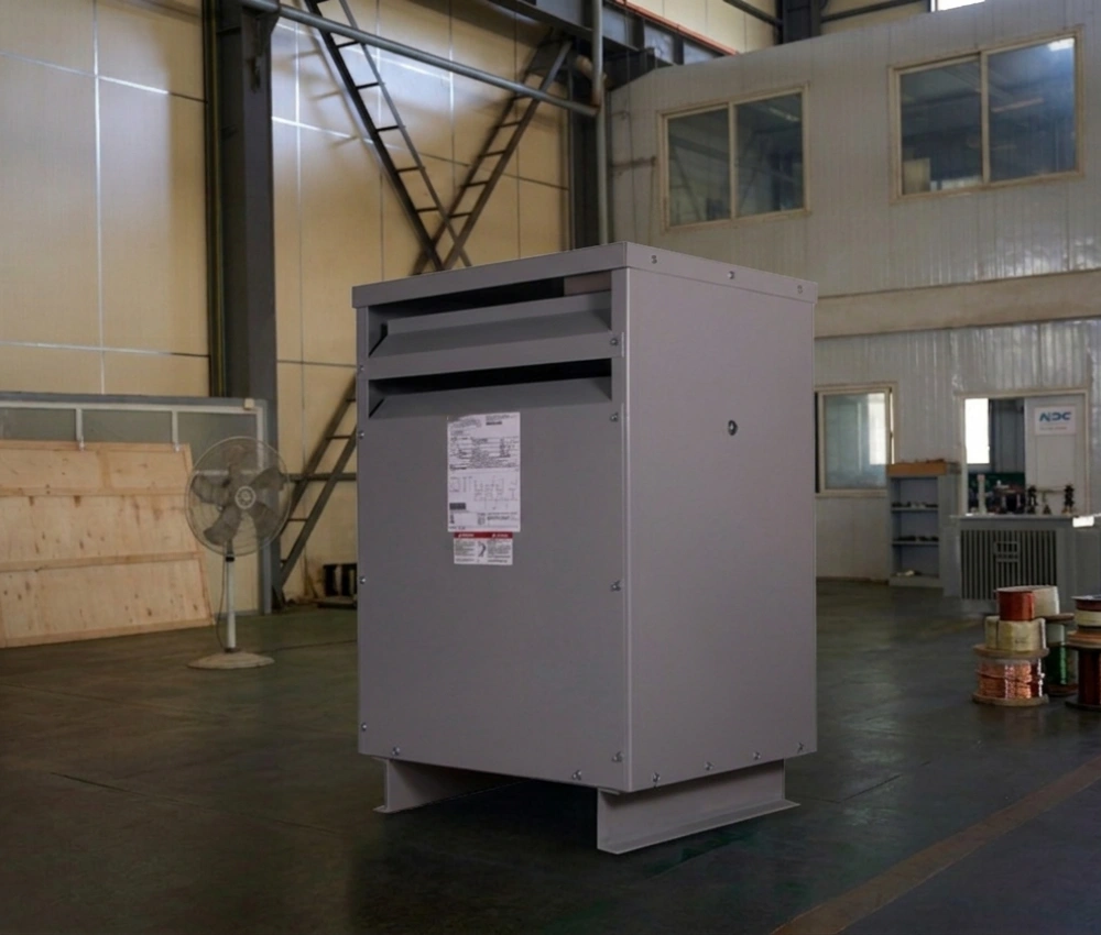
Single Phase Isolation Transformer
The Single Phase Isolation Transformer is a specialized power transformer designed to provide complete electrical isolation between the primary and secondary circuits while ensuring safe and efficient power transmission. By eliminating direct conductive paths between input and output power sources, the transformer effectively suppresses electrical noise, reduces common-mode interference, minimizes transient voltage disturbances, and enhances operational safety for connected equipment. This makes it an ideal solution for sensitive electronic devices, industrial control systems, laboratory instruments, medical equipment, and commercial power applications. Constructed with premium-grade CRGO silicon steel cores and precision-wound copper or aluminum conductors, the Single Phase Isolation Transformer offers exceptional efficiency, low losses, and stable voltage regulation. Its robust insulation system enhances dielectric strength and provides reliable protection against electrical faults and grounding issues. The transformer is available in a wide range of voltage ratings and capacities, making it suitable for both standard and customized electrical distribution requirements. Designed for long-term performance and minimal maintenance, the Single Phase Isolation Transformer can be integrated into industrial automation systems, telecommunications networks, data processing facilities, and specialized power conditioning applications.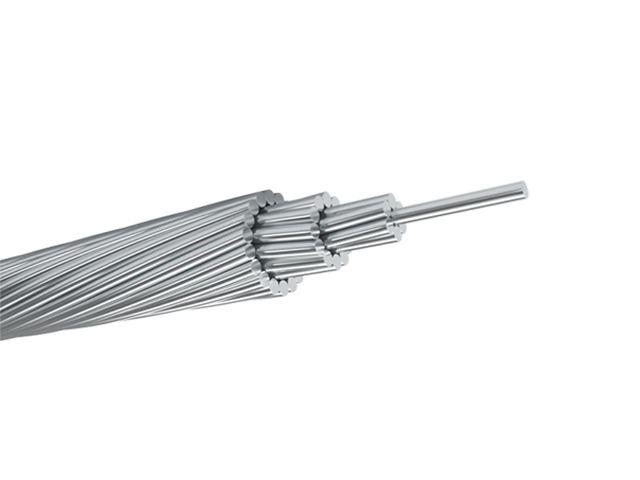
AAAC Moose Conductor Cable
AAAC MOOSE conductor is manufactured in compliance with ASTM B399 or IEC 61089 standards, using high-strength aluminum alloy 6201-T81 for enhanced conductivity and corrosion resistance. Constructed entirely from high-strength aluminum alloy strands, it offers superior mechanical strength and corrosion resistance compared with traditional aluminum conductors. The Moose-size AAAC conductor is particularly suitable for long-span installations, providing excellent sag control and stable operation under heavy mechanical loads. Its all-alloy design ensures uniform conductivity and eliminates steel-related corrosion issues, extending service life in harsh environmental conditions. Manufactured under strict quality management systems, the AAAC Moose Conductor Cable complies with international standards and delivers reliable performance, simplified installation, and reduced lifecycle costs for utility and infrastructure projects worldwide.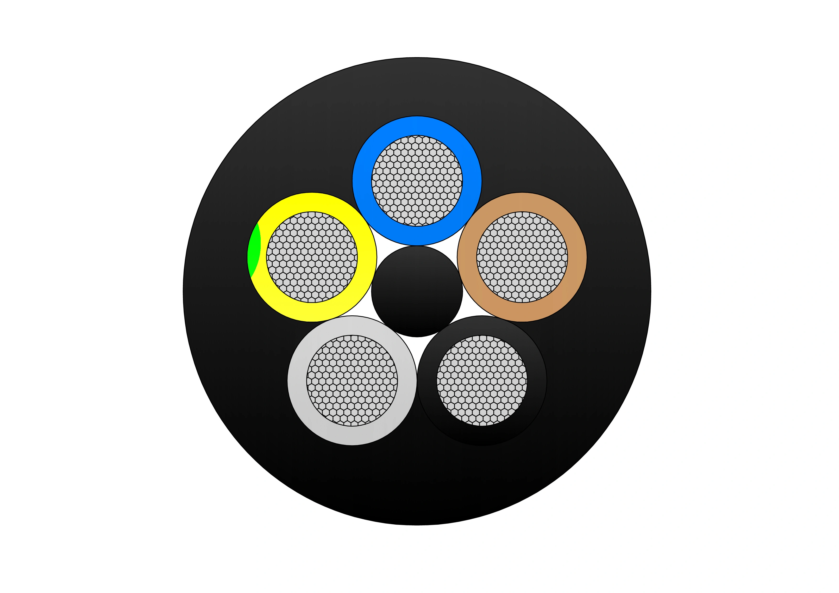
Type 245 Flexible Rubber Mining Cable
The Type 245 Flexible Rubber Mining Cable is an extra-heavy-duty flexible cable purpose-built for the most severe high-voltage underground mining environments. It features finely stranded tinned copper conductors (class 5) for exceptional flexibility and corrosion resistance, EPR (ethylene propylene rubber) insulation for outstanding dielectric strength, thermal stability (90°C continuous rating), and resistance to moisture/heat, an overall tinned copper braid screen providing superior EMI protection and grounding, and an extra-heavy-duty flame-retardant rubber outer sheath engineered to endure extreme abrasion, crushing, impact, cutting, tearing, oils, chemicals, and repeated high-tension reeling/drag. Compliant with AS/NZS 2802 and rigorous mining safety standards, it supports very high tensile loads, frequent flexing, tight bending radii, and reliable operation in wet, dusty, and hazardous mine conditions. The Type 245 is specifically suited for high-power trailing applications in coal and metalliferous mines, powering longwall shearers, continuous miners, face conveyors, shuttle cars, and other critical high-capacity mobile equipment, delivering maximum safety, durability, and uptime.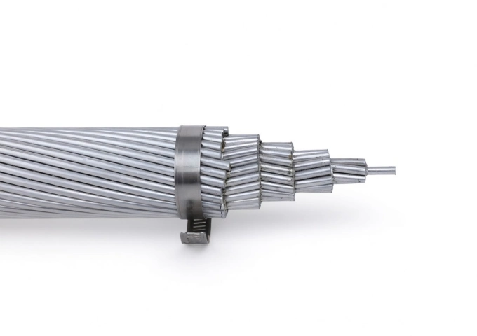
336.4 MCM Tulip AAC Cable
The 336.4 MCM Tulip AAC Cable is a high-performance All Aluminum Conductor designed for demanding overhead power transmission and distribution lines. Manufactured with 19 strands of premium 1350-H19 aluminum wire in a concentric lay configuration, this bare conductor provides excellent electrical conductivity with a low DC resistance of 0.0514 ohms per 1000 ft at 20°C. Featuring an overall diameter of 0.666 inches and a rated breaking strength of 6,150 lbs, the Tulip AAC delivers a robust ampacity of 513 amps while weighing only 315.8 lbs per 1000 ft. Its optimized strength-to-weight ratio minimizes sag and structural loading. Fully compliant with ASTM B-230 and B-231 standards, the 336.4 MCM Tulip AAC Cable offers outstanding corrosion resistance for long-term durability in harsh outdoor environments, making it the preferred choice for utility networks requiring cost-effective, high-reliability bare aluminum conductors.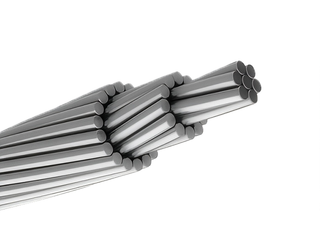
795 MCM DRAKE ACSR Conductor Cable
The ACSR CAA 795 MCM 26/7F DRAKE is a widely used, high-capacity overhead conductor designed for power transmission and distribution systems. It features a rugged construction of 26 hard-drawn 1350-H19 aluminium wires wrapped around 7 galvanized steel strands, forming a strong and conductive concentrically stranded cable. Built to ASTM B232 specifications, this conductor delivers excellent electrical performance, while its steel-reinforced core offers the mechanical strength needed for long-span installations. The steel strands are galvanized to Class A or B, providing reliable corrosion resistance in outdoor environments. With its proven design and high load-handling capabilities, the DRAKE configuration is commonly used across utility networks, particularly for high-voltage transmission lines where strength, conductivity, and longevity are critical. The aluminum 1350-H19 provides excellent corrosion resistance and low electrical resistance (0.0223 Ω/1000ft at 20°C), while the steel enhances sag control over long spans. Suitable for voltages up to 230kV in distribution lines, the 795 MCM Drake ACSR Conductor Cable minimizes line losses and withstands harsh weather, including wind and ice loading.
556.5 MCM DOVE ACSR Conductor Cable
The ACSR CAA 556.5 MCM 26/7F DOVE is a high-capacity, steel-reinforced aluminium conductor designed for the efficient and reliable delivery of electrical power across overhead transmission and distribution lines. Its structure features 26 hard-drawn 1350-H19 aluminium strands wrapped around 7 galvanized steel strands, forming a strong, concentric-lay stranded design. Manufactured in accordance with ASTM B232, this conductor brings together the lightweight, conductive benefits of aluminium with the mechanical strength and durability of galvanized steel. The steel core, treated with Class A or B galvanization, offers essential corrosion protection, especially in harsh weather environments or long-span installations. The DOVE configuration is a popular industry standard for medium- to high-voltage overhead systems, offering excellent performance where long spans and high tension loads are involved. Its optimized aluminium-to-steel ratio makes it well-suited for utility transmission networks, helping reduce line losses while ensuring structural integrity.H-medium-voltage-power-cable-2.jpg)
N2XS(F)H Medium Voltage Power Cable (6/10kV, 12/20kV, 18/30kV)
The N2XS(F)H Medium Voltage Power Cable is engineered for medium voltage power distribution systems operating at 6/10kV, 12/20kV, and 18/30kV, where electrical reliability and fire safety are essential. The cable combines a copper conductor with XLPE insulation and a longitudinally corrugated aluminum sheath that delivers excellent moisture protection and mechanical strength. The LSZH outer sheath minimizes toxic gas release and smoke generation during fire exposure, supporting safer evacuation and equipment protection. Designed and manufactured in compliance with IEC standards, N2XS(F)H cables provide low dielectric losses, high thermal stability, and dependable long-term operation. The metallic sheath enhances grounding and fault current performance, making the cable suitable for critical infrastructure and underground installations.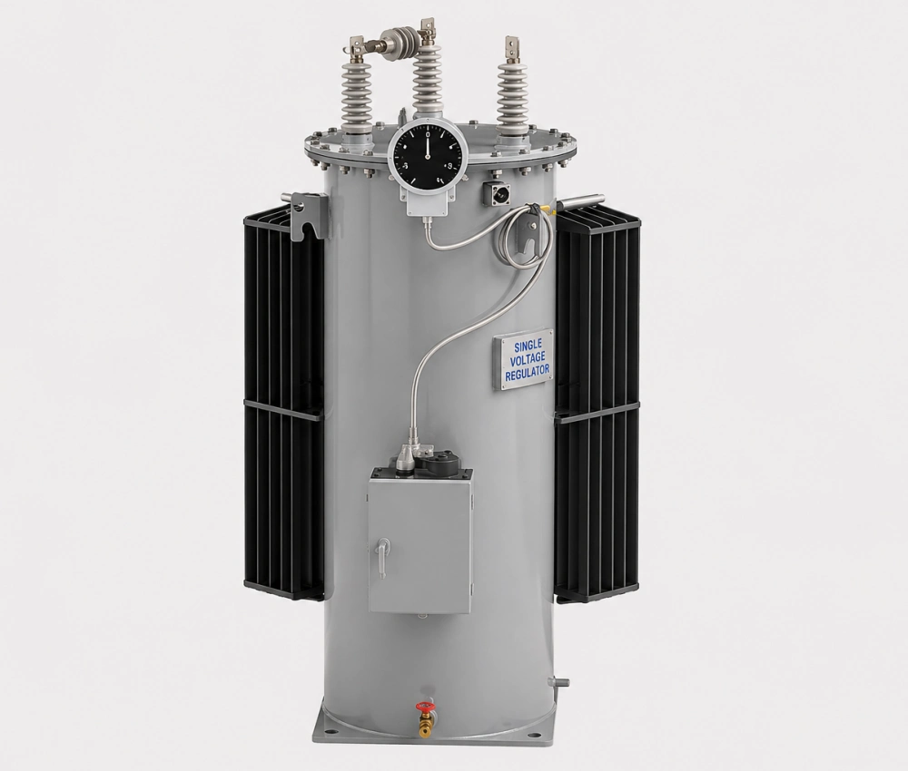
Three Phase Automatic Step Voltage Regulator
The Three Phase Automatic Step Voltage Regulator is a high-performance on-load tap changing device designed to automatically maintain stable voltage levels in medium-voltage distribution networks. Equipped with premium copper windings, low-loss silicon steel cores, and a reliable motorized on-load tap changer, it delivers fast, precise voltage correction with minimal waveform distortion. The intelligent digital controller continuously monitors three-phase voltage and load conditions, making real-time adjustments to ensure consistent output voltage despite fluctuations in supply or demand. Built for outdoor durability, it features a fully sealed oil-immersed tank with advanced corrosion protection, excellent overload capability, and comprehensive protection systems. This regulator significantly improves power quality, reduces line losses, and enhances equipment lifespan across distribution systems.
ALLIANCE AAAC Conductor Cable
ALLIANCE AAAC (All Aluminum Alloy Conductor) cables are manufactured in strict compliance with international standards such as ASTM B399, IEC 61089, and BS EN 50182, making them a high-performance and reliable overhead power transmission and distribution solution. Meeting ASTM B398, B399, IEC 61089, and BS EN 50182 standards, this cable handles ampacity up to 350A at 75°C and voltages up to 33kV. The all-alloy construction avoids bimetallic corrosion, providing better resistance in harsh conditions than ACSR. Reduced weight minimizes sag and installation expenses, supporting longer spans. The Alliance AAAC Conductor Cable delivers low electrical losses, high mechanical endurance, and excellent weather tolerance. Flame-retardant variants available. Perfect for urban grids, renewable projects, and coastal setups, it provides cost-effective, low-maintenance power delivery in overhead applications globally, excelling in reliability and lifespan over conventional conductors.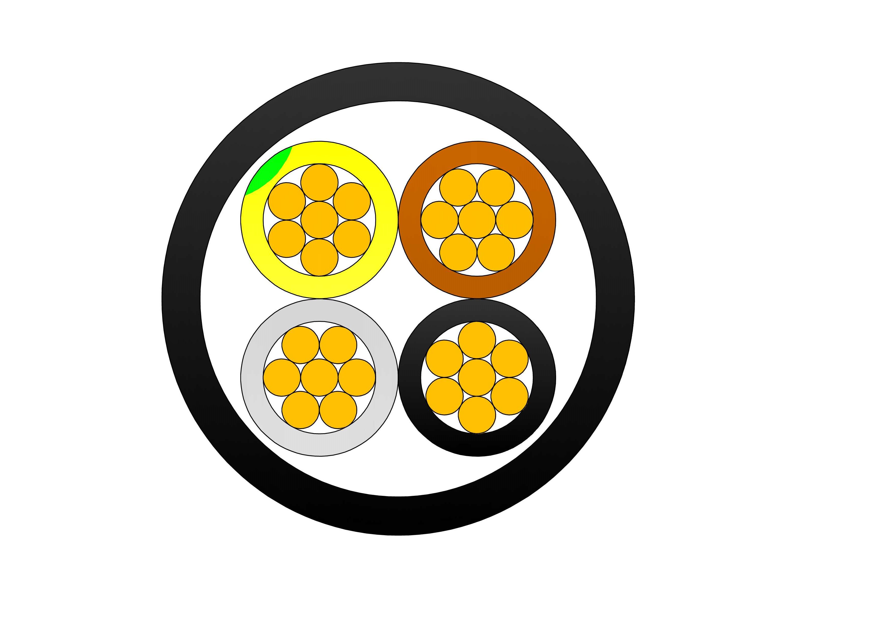
LV Submarine Cable
The Low Voltage Submarine Cable LV XLPE Armoured is a durable underwater power cable designed for reliable low voltage power transmission in marine environments. It features stranded copper or aluminum conductors, cross-linked polyethylene (XLPE) insulation for superior electrical performance, water-blocking layers, galvanized steel wire armour for mechanical protection, and a robust outer sheath resistant to abrasion and corrosion. Rated for 0.6/1kV or 1.8kV, this cable ensures excellent water tightness, high tensile strength, and long-term stability even in harsh seabed conditions. Manufactured according to IEC 60502-1 and submarine cable standards, the Low Voltage Submarine Cable LV XLPE Armoured is ideal for offshore platforms, island interconnections, coastal power supply, and harbor infrastructure. Its strong construction provides outstanding resistance to hydrostatic pressure, marine growth, and mechanical stresses, making it a trusted solution for safe and efficient underwater power distribution.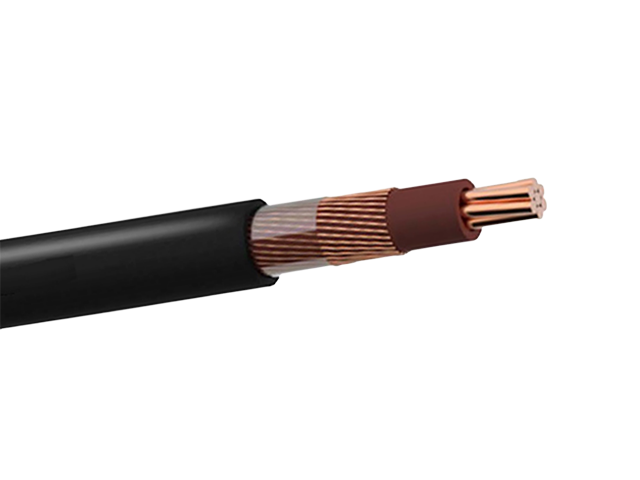
0.6/1kV Aluminum LV Concentric Service Cable with Pilot Communication Cores
The 0.6/1kV Aluminum LV Concentric Service Cable with Pilot Communication Cores is a smart-ready low-voltage cable designed for modern house service connections and secondary distribution. It features compact stranded AA8000 aluminum alloy phase conductors, XLPE insulation, a concentrically arranged aluminum alloy neutral, and two insulated pilot communication cores for remote metering, load management, or fault signaling. The entire assembly is protected by a durable black polyethylene sheath. This design combines excellent electrical performance, high mechanical strength, and communication functionality in one cable, reducing installation costs and enabling smart grid applications. Rated 0.6/1kV, the cable offers superior flexibility and corrosion resistance. It undergoes rigorous quality testing from raw materials to finished product, ensuring consistent conductivity, reliable pilot signal transmission, and long-term durability in aerial or underground environments.
3/0 Fulgar Aluminum Conductor Triplex Overhead Service Drop Cable
3/0 Fulgar Aluminum Conductor Triplex Overhead Service Drop Cable is engineered for high-capacity overhead electrical service connections in utility distribution systems. The cable consists of two insulated aluminum phase conductors twisted around a bare aluminum neutral messenger, ensuring stable electrical transmission and strong mechanical support. Manufactured using high-purity aluminum and weather-resistant insulation compounds, the 3/0 Fulgar Aluminum Conductor Triplex Overhead Service Drop Cable delivers low electrical resistance, excellent corrosion resistance, and reliable long-term performance in outdoor environments. Its optimized conductor design allows efficient installation while maintaining the tensile strength required for aerial service applications. The cable is designed to withstand UV exposure, wind loading, and temperature fluctuations. Comprehensive quality control procedures and systematic testing are applied throughout the manufacturing process to ensure compliance with industry and utility standards and dependable field operation.
10kV Oil Immersed Transformer
The 10kV Oil Immersed Transformer is a high-performance, three-phase distribution transformer engineered for reliable medium-voltage power conversion in AC 50/60Hz systems. Featuring a fully sealed corrugated tank design, it eliminates the need for an oil conservator while providing excellent moisture resistance and extended service life. This transformer excels in energy savings, with up to 30% lower no-load losses compared to older models, making it ideal for modern grid upgrades and sustainable power distribution.
Airdac SNE & CNE Concentric Cable
The Airdac SNE & CNE Concentric Cable is a robust low-voltage aerial service connection cable designed for reliable house service from the distribution network to the consumer meter. It features a circular stranded hard-drawn copper phase conductor insulated with XLPE, surrounded by concentrically arranged neutral and earth conductors, and protected by a black polyethylene sheath. The SNE version provides separate neutral and earth conductors, while the CNE version combines them for simplified earthing. With a nylon ripcord for easy stripping and UV-stabilized materials, this cable offers excellent mechanical strength, electrical performance, and long-term durability. Manufactured to SANS 1507-6 and related standards, the Airdac SNE & CNE Concentric Cable undergoes rigorous quality testing from raw materials to finished product, ensuring safe, tamper-resistant, and vandal-proof performance in overhead or underground installations.Welcome your inquiry
Honesty, Integrity, Frugality, Activeness and Passion