Electricity Science and Safety: 300 Questions on Substations (Part 4)
2025-08-29
Transformers play a critical role in power systems by enabling efficient voltage regulation and energy transmission. However, over time, these vital components can encounter various problems due to aging, environmental stress, electrical faults, or mechanical failures. Common issues include overheating, abnormal oil levels, insulation degradation, unusual noises, or internal short circuits. If left unaddressed, such problems may lead to equipment failure, power outages, fire hazards, or safety risks.
This section explores how to identify and resolve transformer-related issues through proven diagnostic methods—such as infrared thermography, oil analysis, and partial discharge detection—alongside preventive maintenance strategies and emergency response actions. By examining real-world questions and answers, readers will gain practical insights into safe and effective transformer operation and fault management.
151. Why is it necessary to install low voltage lockout for overcurrent protection?
A: The operating current of the overcurrent protection is set according to the maximum load current to be avoided. In some cases, it cannot meet the sensitivity requirements. Therefore, in order to improve the sensitivity of the overcurrent protection in the event of a short circuit fault and improve the conditions for avoiding the maximum load current, a low voltage lockout is added to the overcurrent protection.
152. Why are overcurrent protection devices installed on all three sides of a three-winding transformer? What is their protection range?
A: When a busbar short-circuit fault occurs on any side of the transformer, overcurrent protection activates. Because overcurrent protection is installed on all three sides, it can selectively clear the fault without shutting down the transformer. Overcurrent protection on each side serves as backup protection for the busbar and line on that side, while overcurrent protection on the main power supply side serves as backup protection for the other two sides and the transformer.
153. What kind of fault gas protection action?
Answer: ( 1 ) Multiphase short circuit inside the transformer. ( 2 ) Turn-to-turn short circuit, short circuit between the winding and the core or the casing. ( 3 ) Core failure. ( 4 ) Oil level drop or oil leakage. ( 5 ) Poor contact of the tap changer or loose welding of the wires.
154. Under what circumstances is it necessary to disable the differential protection of a running transformer?
A: The differential protection should be disabled when any of the following conditions occur during transformer operation: ( 1 ) When the secondary circuit of the differential protection and the current transformer circuit are changed or calibrated. ( 2 ) When the relay protection personnel measure the current phase and differential voltage of the differential circuit. ( 3 ) When one phase of the differential protection transformer is disconnected or the circuit is open. ( 4 ) When obvious abnormality occurs in the differential circuit. ( 5 ) When the circuit breaker trips due to a false trip.
155. How are the protection ranges of sections I , II , III , and IV of zero-sequence protection divided?
A: Section I of the zero-sequence protection is set based on the maximum zero-sequence current flowing through the protection device when avoiding a single-phase short circuit at the end of the line. It cannot protect the entire length of the line. Section II of the zero-sequence protection is set in conjunction with Section I of the zero-sequence protection of the adjacent line at the same location as the protection installation . It not only protects the entire length of the line but can also extend to adjacent lines. Section III of the zero-sequence protection works in conjunction with Section II of the adjacent line and serves as backup protection for Sections I and II . Section IV generally serves as backup protection for Section III .
156. Why does the distance protection malfunction when the voltage suddenly loses?
A: Distance protection operates when the measured line impedance value ( Z=U/I ) is equal to or less than the set value. This means that when the voltage applied to the impedance relay decreases and the current flowing through it increases to a certain value, the relay operates. The voltage generates a braking torque. Current generates an operating torque. If the voltage suddenly drops, the braking torque also suddenly becomes very small. However, the current loop generates an operating torque generated by the load current. If the locking circuit fails at this point, the distance protection will malfunction.
157. Why does the impedance relay in the distance protection device use 0° wiring?
Answer: Distance protection is a protection device that reflects the distance from the installation location to the fault. Therefore, the impedance relay as a distance protection measuring element must correctly reflect the distance from the short-circuit point to the protection installation location and not be affected by the fault type. The use of 0° wiring of phase-to-phase voltage and phase-to-phase current can meet the above requirements, so distance protection generally uses 0° wiring.
158. How should the line distance protection voltage circuit be switched?
A: When switching a transmission line from one busbar to another due to power system operation requirements or load balancing, the voltage used by the distance protection must also be switched to the voltage transformer on the other busbar. During the switching process, the distance protection must not lose voltage. If the voltage is disconnected, the DC power supply must be disconnected first. This will prevent the distance protection from tripping inadvertently.
159. What should be paid attention to during the operation of distance protection?
Answer: The distance protection should have a reliable power supply during operation , and the operating voltage transformer should be prevented from back-charging the standby voltage transformer, rendering the line break locking device ineffective. If the secondary fuse of the voltage transformer happens to blow at this time, the distance protection will malfunction due to voltage loss.
160. How are electromagnetic relay protection and transistor relay protection started?
Answer: In electromagnetic relay protection devices, after the relay coil is energized, the armature-band contact connects or disconnects the circuit to start protection; while in transistor protection devices, after the current reactance transformer is energized, the potential change formed on its secondary side causes the transistor to turn on or off to start protection.
161. What special protections does a 500KV transformer have? What is its function?
Answer: ( 1 ) Overexcitation protection is used to prevent the transformer from sudden load shedding or a sudden increase in magnetic flux density due to overvoltage in the excitation system, which may cause overheating of the core and other metal parts. ( 2 ) 500kV and 220kV low impedance protection. It serves as a backup protection for differential protection when a phase-to-phase short circuit occurs in the transformer windings and lead wires.
162. What are the regulations for the use of current phase comparison bus differential protection?
Answer: ( 1 ) The busbar oil circuit breaker must be in operation, and both busbars must have power supply circuits. ( 2 ) When the busbar oil circuit breaker is disconnected, the busbar differential function is non-selective. ( 3 ) When the busbar is bypassed, the busbar current circuit must be switched to the differential circuit. ( 4 ) When operating with a single busbar, a non-selective three-pole small knife switch should be switched on before the switching operation. At this time, the busbar fault will cut off all power supply oil circuit breakers.
163. What are the advantages and disadvantages of current phase comparison bus differential protection?
Answer: It is flexible and convenient to operate, eliminating the possibility of human error. The wiring and fixed connection method of the TA circuit is simple, the action is adjustable , and the selectivity is strong.
164. What protection functions does the CLS166 microcomputer protection have?
Answer: It is equipped with three-stage phase-to-phase distance protection, two-stage grounding distance protection that is activated according to the zero-sequence current exceeding the limit, one stage of overcurrent protection IJ , one stage of overcurrent protection IJP that is automatically activated after TV line is disconnected , and three-phase primary reclosing.
165. How to change the set value zone of CSL166 microcomputer line protection?
Answer: ( 1 ) First, press the dial button on the panel to select the desired setting area. ( 2 ) The panel displays SET-CHG , P-RST , and press the signal reset button to confirm. The confirmation time is about 20 seconds . After observing that the panel displays the correct input quantity change, press the QUIT button to reset the LCD. ( 3 ) Press the SET button and the right button to select the print menu PNT , and press the SET button to confirm. This will print the setting sheet for verification of the setting.
166. What does the DFP-500 protection exception report contain ?
Answer: When the operation is abnormal or the device self-diagnoses an error alarm, the LCD will display an abnormality report, which includes the time and corresponding content when the abnormality or self-diagnostic error occurred.
167. What could be the cause of the alarm light? How should I handle it?
A: This indicates that the CPU has a fault and should be stopped and the CPU plug-in replaced. It should be noted that this phenomenon may also occur when the CPU plug-in test switch is in the " debug " position, the monitoring plug-in is in the running position, and the CPU inspection switch is not exited.
168. What is quasi-simultaneous paralleling? What are the conditions for paralleling?
Answer: When the following conditions are met or the deviation is not large, the paralleling method for closing the power supply switches is quasi-synchronous paralleling. ( 1 ) The voltages on both sides of the parallel switch are equal, with a maximum allowable correlation of less than 20% . ( 2 ) The frequencies of the power supplies on both sides of the parallel switch are the same. Generally, a frequency difference of 0.5 Hz is sufficient for paralleling. ( 3 ) The phase angles of the voltages on both sides of the parallel switch are the same. ( 4 ) The phase sequence on both sides of the parallel switch is the same.
169. What will happen if one coil of a synchronous relay loses power during normal operation? How should it be handled?
A: When one coil of a synchronous relay loses power, the relay will make a sound and enter the operating state, that is, the lower contact opens and the upper contact closes. At this time, the synchronous reclosing circuit breaker should be shut down and a professional should be notified to investigate the cause.
170. What is the principle of high-frequency remote tripping?
Answer: This type of protection uses high-frequency current to transmit tripping signals. When a fault occurs in the zone, after the protection device stage I is activated, the circuit breaker on this side will be instantly tripped, and a high-frequency signal will be sent to the opposite side at the same time. The side that receives the high-frequency signal will compare the high-frequency signal with the protection stage II action. If stage II is activated, the action will be accelerated to trip, thereby achieving rapid removal of the entire line of faults in the zone.
171. Why should 220KV lines be equipped with comprehensive reclosing devices?
A: 220kV lines are neutral-grounded systems. Because single-phase grounding faults are the most common, circuit breakers are equipped with split-phase operating mechanisms. When a single-phase grounding fault occurs, the protection only trips the circuit breakers on both sides of the faulty phase, while the unfaulted phases remain untripped. This prevents operational overvoltage and improves system stability. When an interphase fault occurs, the protection device trips the three-phase circuit breakers on both sides. Alternatively, when single-phase tripping with single-phase reclosing or three-phase tripping with three-phase reclosing is required, this can also be accomplished using the integrated reclosing mechanism.
172. How many operating modes does the integrated reclosing system have? How do they work?
Answer: The integrated reclosing is achieved in three ways by the switch QK . ( 1 ) Integrated reclosing mode. After a single-phase fault trips, the single phase recloses. After reclosing on a permanent fault, the three phases reclose. After a phase-to-phase fault trips the three phases, the three phases reclose. After reclosing on a permanent fault, the three phases trip again. ( 2 ) Three-phase reclosing mode. After any type of fault, the three phases trip, the three phases reclose (check synchronization or no voltage). After reclosing on a permanent fault, the three phases trip again.
( 3 ) Single-phase reclosing mode. In case of single-phase fault, the fault phase is tripped and then the single phase is reclosed. In case of reclosing on permanent fault, the three phases are tripped. In case of interphase fault, the three phases are tripped and then the circuit breaker does not reclose.
173. Why is it necessary to use post-reclosing acceleration on the side of the dual power supply line equipped with a no-pressure identification reclosing switch?
A: When the no-voltage identification reclosing device recloses the circuit breaker on a permanent fault line, the accelerated protection after reclosing will operate without time limit, causing the circuit breaker to trip immediately. This can avoid expanding the scope of the accident, benefit system stability, and protect electrical equipment from damage.
174. Why should the starting circuit of the automatic transfer device be connected in series with the voltage contacts of the backup power supply voltage relay?
Answer: In order to prevent the automatic transfer device from being activated when the backup power supply is out of power and transferring to the power-free equipment, the voltage contacts of the backup power supply voltage relay are connected in series in the starting circuit of the automatic transfer device to check whether the backup power supply has voltage, ensure the correctness of the automatic transfer device's operation, and also speed up the operation time of the automatic transfer device.
175. Why are the no-voltage contacts of the two voltage relays on the high and low voltage sides of the transformer automatic switching device connected in series in the starting circuit?
A: This is to prevent the automatic transfer device from malfunctioning due to a blown voltage transformer fuse, and to ensure the correct operation of the automatic transfer device. In this way, even if one set of voltage transformer fuses blows, the automatic transfer device will not malfunction.
176. What are the starting methods of the fault recorder?
A: The starting mode should be selected to ensure that the fault recorder can start reliably when any type of fault occurs in the system . Generally, the starting modes include the following: negative sequence voltage, low voltage, overcurrent, zero sequence current, and zero sequence voltage.
177. How does the synchronous detection relay work?
A: The two coils of the synchronous detection relay are connected to the running and starting synchronous voltage busbars, respectively. When voltage appears on the synchronous voltage busbar, the synchronous detection relay operates. If the voltage phase difference on both sides of the synchronous point exceeds the set operating angle of the synchronous detection relay, the relay operates, the normally open contact opens, and the closing pulse circuit is disconnected, preventing the circuit breaker from closing.
178. What are the basic requirements for oscillation locking devices?
Answer: ( 1 ) When there is no fault in the power system and oscillation occurs, the protection should be locked, and the lock should not be released as long as the oscillation continues. ( 2 ) When a short circuit occurs within the protection range, regardless of whether the system oscillates, the protection device can operate correctly and cut off the fault.
179. What are the hazards of running a transformer at extreme temperatures for a long time?
A: Generally, the primary insulation of a transformer is Class A insulation, with a maximum operating temperature of 105 °C. During operation, the temperature of the transformer windings should be 10-15 °C higher than the upper oil temperature. If the upper oil temperature of a transformer is consistently around 80-90 °C during operation , meaning the windings are constantly around 95-105 °C, the high temperature will cause severe insulation aging, accelerate the deterioration of the insulating oil, and shorten its service life.
180. What are the consequences of parallel operation of transformers that do not meet the parallel operation conditions?
A: When transformers with different transformation ratios are operated in parallel, circulating currents will be generated, affecting the transformer's output power. If transformers with unequal percentage impedances are operated in parallel, the load cannot be distributed proportionally to the transformer's capacity, also affecting the transformer's output power. When transformers with different wiring groups are operated in parallel, the transformers may short-circuit.
181. What is electrical equipment in use?
Answer: ( 1 ) All electrical equipment that carries voltage. ( 2 ) Some electrical equipment that carries voltage. ( 3 ) Electrical equipment that carries voltage once it is operated.
182. How are high voltage and low voltage of electrical equipment divided?
Answer: High voltage: equipment with a voltage of 250V or above to the ground; Low voltage: equipment with a voltage of 250V or below to the ground.
183. What are the regulations regarding on-duty personnel removing or crossing the fence to carry out work?
A: The specific regulations are: ( 1 ) Regardless of whether the high-voltage equipment is energized or not, on-duty personnel must not remove or cross the fence to carry out work. ( 2 ) If it is necessary to remove the fence: 1 ) A supervisor must be present. 2 ) The following safety distances must be met: 10kV is 0.7 meters ; 66kV is 1.5 meters ; 220kV is 3 meters .
184. What kind of work is meant by total power outage?
Answer: ( 1 ) All indoor high-voltage equipment is powered off (including overhead lines and cable leads). ( 2 ) All doors leading to adjacent high-voltage rooms are locked. ( 3 ) All outdoor high-voltage equipment is powered off (including overhead lines and cable leads).
185. What does partial power outage and no power outage mean?
Answer: Partial power outage work refers to: ( 1 ) Partial power outage of high-voltage equipment. ( 2 ) Or a complete power outage in a room, but the doors leading to the adjacent high-voltage room are not all locked. Non-power outage work refers to: ( 1 ) Work that does not require power outage and does not pose a risk of accidental contact with conductive parts. ( 2 ) Work that is permitted on the casing of live equipment or on conductive parts.
186. What regulations must be followed when working on high-voltage equipment?
Answer: ( 1 ) Fill out a work ticket or give a verbal telephone order. ( 2 ) At least two people should work together. ( 3 ) Complete organizational and technical measures to ensure the safety of the staff.
187. What regulations should be followed when resuming work the next day after a work interruption?
Answer: When resuming work the next day: ( 1 ) You must obtain permission from the duty officer. ( 2 ) You must retrieve your work permit. ( 3 ) The person in charge of the work must carefully recheck that the safety measures meet the requirements of the work permit before you can resume work. ( 4 ) Workers are not allowed to enter the work area without the guidance of the person in charge of the work or a guardian.
188. Where is the sign “ Do not close the switch, someone is working ” hung?
Answer: A sign that reads " Do not close the switch, someone is working " should be hung on the operating handles of switches and knife switches that can supply power to the work site once closed .
189. What are the requirements for using insulating rods to open and close disconnectors or for opening and closing disconnectors and circuit breakers through transmission mechanisms?
Answer: ( 1 ) Use insulating rods to open and close disconnectors or mechanically open and close disconnectors and circuit breakers. ( 2 ) Wear insulating gloves. ( 3 ) When operating outdoor high-voltage equipment on rainy days: insulating rods should have rain covers and insulating boots should be worn; if the grounding grid resistance does not meet the requirements, insulating boots should also be worn on sunny days. ( 4 ) Switching operations are prohibited during thunderstorms.
190. What are the requirements for installing grounding wires on indoor power distribution equipment?
Answer: ( 1 ) They should be installed at the designated locations on the conductive parts of the device. ( 2 ) The paint at these locations should be scraped off and black marks should be made.
191. What is a switching operation? What is a switching operation?
A: Electrical equipment is classified into three states: operation, standby (cold standby and hot standby), and maintenance. The process of changing equipment from one state to another is called switching, and the operation performed is called a switching operation.
192. What operational errors should be avoided during switching operations?
Answer: The key points to prevent misoperation are: ( 1 ) Accidentally opening or closing circuit breakers or disconnectors. ( 2 ) Opening or closing disconnectors under load. ( 3 ) Hanging a ground wire under power (or closing a grounding knife switch under power). ( 4 ) Closing the switch with the ground wire on. ( 5 ) Asynchronous paralleling. ( 6 ) Accidentally switching on or off relay protection and grid automatic devices. In addition to the above 6 points, preventing operators from accidentally entering live compartments, accidentally climbing onto live structures, and avoiding personal electric shock are also key points to pay attention to during switching operations.
193. How to install and remove grounding wires?
Answer: The specific procedures are as follows: ( 1 ) When installing and removing the grounding wire, two people must be involved. After verifying that the equipment is indeed without power, the maintenance equipment should be immediately grounded and the three phases should be short-circuited. ( 2 ) When installing and removing the grounding wire, an insulating rod should be used and insulating gloves should be worn. ( 3 ) When installing the grounding wire, the grounding end must be connected first, followed by the conductor end, and the contact must be firm. ( 4 ) The order of removing the grounding wire is the opposite of that of installing the grounding wire.
194. What items should be checked after the circuit breaker is operated during power outage?
Answer: ( 1 ) The red light should be off and the green light should be on. ( 2 ) The on/off indicator of the operating mechanism should be in the open position. ( 3 ) The ammeter indication should be zero.
195. What should you pay attention to when closing the circuit breaker electrically?
A: When the circuit breaker is electrically closed, the green light should flash when the operating handle is turned to the pre-closing position. When the operating handle is turned to the closing end position, the ammeter should be checked at the same time. When the red light comes on, release the handle and the handle will automatically return to the closed position.
196. What are the basic requirements for isolating switches?
Answer: ( 1 ) The disconnector should have a clear disconnect point. ( 2 ) The disconnect point of the disconnector should have reliable insulation. ( 3 ) It should have sufficient short-circuit stability. ( 4 ) It should have a simple structure and reliable operation . ( 5 ) The main disconnector and its grounding switch should be interlocked.
198. Which items should be filled in the operation ticket?
Answer: ( 1 ) Pull and close the switches and circuit breakers. ( 2 ) Check the position of the switches and circuit breakers. ( 3 ) Check whether the grounding wire is removed. ( 4 ) Check the load distribution. ( 5 ) Install or remove the fuse of the control circuit or voltage transformer circuit. ( 6 ) Switch the protection circuit and check whether there is no voltage. ( 7 ) Install and remove the grounding wire. ( 8 ) Turn on and off the automatic device, control handle and reclosing device.
199. What measures should be taken with the fault recorder before the busbar is powered off or the voltage transformer is shut down?
Answer: Before the busbar is powered off or the voltage transformer is shut down, be sure to switch the voltage switch of the fault recorder to the running busbar or running voltage transformer to prevent the fault recorder from malfunctioning due to loss of voltage.
200. What are the requirements for filling in the voltage level in the work ticket and the order of filling in the safety measures column?
Answer: ( 1 ) The voltage level should always be written as "KV" . ( 2 ) The items in the safety measures column should be numbered.
Recommended Reading
Related Articles


Related Products
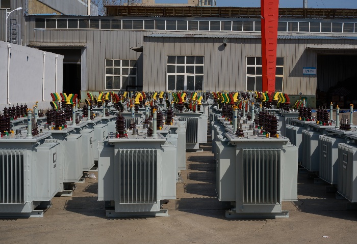
1000kVA Oil Immersed Transformer
NPC ELECTRIC's 1000kVA oil-immersed transformer is made of high-quality silicon steel sheets and high-quality insulation materials, with high efficiency, low loss, and long life. The product complies with international standards such as IEC 60076 and GB 1094, and has passed strict type tests and factory tests to ensure safety and reliability. High-quality windings and robust mechanical design provide strong short-circuit withstand capability and thermal stability. With low operating noise and reduced maintenance requirements, the transformer is well suited for industrial, commercial, and utility distribution networks.
Triplex URD Cable
The Triplex URD Cable is a cost-effective and reliable 600V underground residential distribution cable engineered for service entrance and secondary power delivery. It consists of three insulated AA8000 aluminum alloy phase conductors and a concentric neutral, all encased in a durable black polyethylene sheath. The triplex design offers a compact footprint, excellent flexibility, and easy handling during direct burial installation. With XLPE insulation, this cable provides superior electrical performance and moisture resistance. Lightweight and corrosion-resistant, the Triplex URD Cable is an economical alternative to copper while maintaining high conductivity and mechanical strength. Manufactured to UL 854 and ICEA standards, it undergoes extensive quality testing to ensure consistent performance and long service life in underground environments.
H07RN-8-F EN 50525-2-21 Flexible Rubber Cable
The H07RN-8-F EN 50525-2-21 Flexible Rubber Cable is a versatile, heavy-duty flexible cable designed for demanding applications in harsh, wet environments. It features fine-stranded class 5 bare copper conductors for excellent flexibility and conductivity, EPR (ethylene propylene rubber) core insulation for high dielectric strength and thermal resistance (90°C continuous, 250°C short-circuit), an overall tinned copper braid screen (optional for some variants), and a robust polychloroprene (neoprene) outer sheath providing superior oil resistance, flame retardancy (IEC 60332-1), abrasion/chemical resistance, and weatherproofing. The AD8 rating ensures submersible performance up to 10 meters depth for continuous use in wet or underwater conditions. Compliant with EN 50525-2-21 and VDE 0285 standards, it offers mechanical robustness, ozone resistance, and long service life. The H07RN-8-F is ideal for mobile equipment, construction sites, mining, marine applications, and industrial power supply where flexibility, water immersion, and safety are critical.
37.5kVA Single Phase Pad Mounted transformer
The 37.5kVA Single Phase Pad Mounted transformer with high voltage (HV) specifications of 24.94GRDY/14.4 kV and low voltage (LV) of 240/120V. At its core lies a robust tank, constructed from resilient alloy 304 stainless steel, guaranteeing longevity even in the harshest conditions. The HV and LV windings, equally critical components, are meticulously crafted from high-quality aluminum to ensure unwavering performance.
6 Chola Aluminum Conductor Quadruplex Overhead Service Drop Cable
Introducing the 6 Chola Quadruplex Service Drop Cable, a versatile overhead solution for three-phase secondary distribution with neutral. Built with three 6 AWG aluminum phase conductors and one neutral messenger (7-strand) insulated with polyethylene or XLPE and formed into a quadruplex assembly, it meets ASTM and ICEA requirements for 600V service. The tough insulation offers outstanding protection against UV rays, moisture, tree contact, and abrasion. Self-supporting messenger design ensures easy pulling and reduced sag during installation. The 6 Chola Quadruplex Service Drop Cable supports efficient power transfer with low voltage drop and high durability in extreme temperatures. Popular for its lightweight construction and reduced installation time, it is the choice for electricians and utilities. Widely deployed in housing developments, commercial services, and temporary power setups, this cable ensures safe, long-lasting overhead connections from distribution transformers to customer service entrances worldwide.
Duplex Service Drop Cable
The Duplex Service Drop Cable is a reliable overhead cable for secondary power distribution from the utility pole to the service entrance. Featuring two insulated phase conductors (aluminum or ACSR) twisted around a bare or covered neutral messenger wire, it offers excellent mechanical strength and weather resistance. Insulation options include XLPE, PE, or PVC for superior UV, moisture, and abrasion protection. Compliant with ASTM B-230, B-231, ICEA S-76-474, and ANSI/ICEA standards, this cable supports low-voltage applications up to 600V. Lightweight design facilitates easy installation with reduced sag and long spans. The Duplex Service Drop Cable ensures minimal power losses, high tensile strength from the messenger, and long service life in harsh outdoor conditions. Ideal for residential, commercial, and rural electrification projects requiring safe, cost-effective aerial service connections worldwide.
Copper Conductor Duplex Service Drop Cable 600V
The Copper Conductor Duplex Service Drop Cable 600V is a high-performance overhead cable for secondary power distribution from utility poles to service entrances. Featuring two insulated copper conductors (phase and neutral) twisted around a bare or insulated neutral messenger, it offers superior conductivity and mechanical strength. Insulation options include XLPE or PE for excellent UV, moisture, and abrasion resistance. Compliant with ASTM B-1, B-2, B-3, B-8, ICEA S-76-474, and ANSI/ICEA standards, this cable supports 600V applications with low voltage drop and high current capacity. The robust design ensures reduced sag, easy installation, and long service life in harsh weather conditions. The Copper Conductor Duplex Service Drop Cable 600V delivers minimal power losses and reliable performance for single-phase service drops. Widely used in urban, suburban, and rural electrification projects requiring premium copper overhead connections with enhanced durability and safety.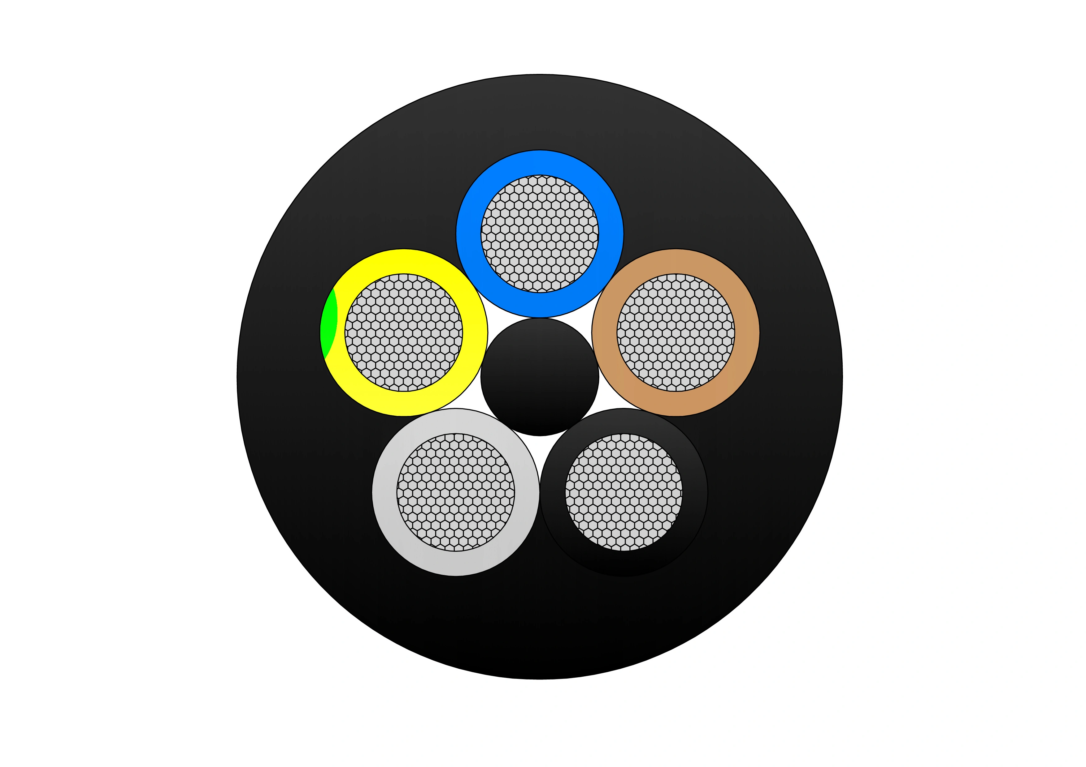
NTSCGECEWOU 3.6/6kV, 6/10kV, 8.7/15kV and 12/20kV Cable
The NTSCGECEWOU 3.6/6kV, 6/10kV, 8.7/15kV and 12/20kV Cable is a flexible, heavy-duty medium-voltage trailing/reeling cable designed for demanding mining and tunnelling operations. It features class 5 finely stranded tinned copper phase conductors for superior flexibility and corrosion resistance, semi-conductive conductor and insulation screens for field control, EPR (ethylene propylene rubber) insulation providing high dielectric strength and 90°C continuous operation, individual copper wire screens serving as earth conductors, control conductors, a monitoring conductor (ÜL), and a robust rubber outer sheath resistant to oil, flame, abrasion, tearing, and mechanical stress. Compliant with DIN VDE 0250, it supports high tensile loads, fast reeling speeds, tight bending radii, and effective EMC shielding across voltage ranges. The NTSCGECEWOU ensures safe, reliable MV power supply to mobile equipment such as shearers, tunnel boring machines, and conveyors in harsh underground and opencast environments, minimising downtime and enhancing operational efficiency.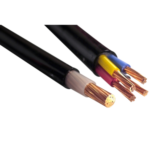
600/1000V PVC Insulated Cable to IEC 60502-1 Standard
The 600/1000V PVC Insulated Low Voltage Power Cable is designed for reliable power transmission in low-voltage electrical systems. Manufactured with high-quality copper or aluminum conductors and PVC insulation, this cable provides stable electrical performance, good flexibility, and long service life. The PVC insulation offers effective protection against moisture, abrasion, oils, and common chemicals, making the cable suitable for both indoor and outdoor installations. Rated at 600/1000 volts, the cable ensures safe and efficient power distribution under normal operating conditions. Its robust insulation structure supports consistent current flow while maintaining electrical safety. The cable is easy to install, route, and terminate, making it a practical solution for residential, commercial, and industrial power networks. With dependable insulation performance and mechanical durability, this low voltage power cable meets the demands of everyday electrical infrastructure.
500kVA Three Phase Pad Mounted Transformer
The 500kVA three-phase pad transformer is an efficient and sturdy power equipment designed for commercial, industrial and distribution systems. It has a compact design and a protective casing that meets NEMA 3R or higher standards. It is suitable for various outdoor environments and can effectively resist external factors such as weather, dust and moisture. It can meet the power needs of different regions and has a variety of optional functions, such as load regulation and temperature control systems, to further improve its operating efficiency and safety. The built-in protection device can effectively prevent overload, short circuit and other faults to ensure the safe and reliable operation of the power system.
800kVA Dry Type Transformer
NPC ELECTRIC 800kVA Dry-Type Transformer provides reliable, oil-free power distribution with a compact design. Featuring advanced insulation and cooling systems, it ensures safe, low-maintenance operation for industrial and commercial use. With 800kVA capacity, it delivers efficient and environmentally friendly performance. Its dry-type ventilated or encapsulated construction supports zero fluid maintenance, eliminates leak/spill concerns, and fits seamlessly into high-load, high-traffic, or environmentally restricted spaces. It targets efficiencies approximately 99.36–99.38% at 35% load (consistent with DOE 2029 levels for higher kVA ranges in low-voltage dry-type category), manages harmonics robustly, accommodates overloads, and provides exceptional reliability with minimized lifecycle costs and environmental benefits.
80kVA Dry Type Transformer
80kVA dry-type transformer launched by NPC ELECTRIC adopts advanced dry insulation technology, has the advantages of high efficiency, environmental protection, and safety, and is widely used in industrial, commercial, and residential power systems. The transformer has a compact design, strong load-bearing capacity, stable operation, and effectively reduces energy loss. The oil-free structure reduces the risk of fire, meets modern green environmental standards, and is suitable for use in environments with high requirements for power stability and low noise.
200kV High Voltage Power Transformers – Reliable & Efficient Solutions
The 200kV High Voltage Power Transformer is engineered to support large-scale power transmission systems requiring high reliability, electrical efficiency, and long-term operational stability. Designed for modern grid infrastructures, this transformer enables safe and efficient voltage transformation across extended transmission distances while minimizing energy losses. Its oil-immersed insulation system ensures strong dielectric performance and effective thermal management under continuous high-voltage stress. The transformer structure is optimized to withstand electrical, thermal, and mechanical loads, supporting stable operation under fluctuating demand conditions. Precision manufacturing and advanced design techniques contribute to low maintenance requirements and extended service life. Suitable for utility substations and critical power nodes, this transformer delivers dependable performance for high-capacity transmission and grid interconnection projects.
NAYY-J/NAYY-O Cables
The NAYY-J/NAYY-O Solar Cables provide cost-effective, reliable power distribution in photovoltaic systems. With sector-shaped or round aluminum conductors, PVC core insulation, and robust PVC outer jacket, they meet VDE 0276 requirements. NAYY-J includes a protective earth conductor, while NAYY-O is without. These cables excel in wet environments with superior water and chemical resistance, suitable for direct burial without additional protection. UV-stabilized and mechanically strong, they withstand soil stress and installation pulling forces. Low-weight aluminum reduces handling efforts, making them popular for extensive solar parks. NAYY-J/NAYY-O Solar Cables ensure efficient energy transfer with minimal losses, supporting sustainable solar infrastructure worldwide.
Steel Wire Armoured Cable (SWA Cable) for Power Distribution Systems
The Steel Wire Armoured Cable (SWA Cable) is a high-performance power cable designed for applications requiring exceptional mechanical protection and reliable electrical transmission. Constructed with copper or aluminum conductors, premium XLPE insulation, galvanized steel wire armour, and a durable PVC outer sheath, the cable offers outstanding durability in demanding environments. The galvanized steel wire armour provides excellent tensile strength, impact resistance, and protection against external mechanical damage, making the cable suitable for underground installations, direct burial applications, and industrial facilities. XLPE insulation delivers superior dielectric properties, low electrical losses, and continuous operating temperatures up to 90°C. The robust PVC sheath protects against moisture, chemicals, abrasion, UV exposure, and environmental stress, ensuring a long operational lifespan. Manufactured according to IEC 60502-1, IEC 60502-2, and BS 5467 standards, the cable is widely used in power distribution networks, renewable energy projects, utility infrastructure, and industrial plants. The Steel Wire Armoured Cable combines electrical reliability, mechanical strength, and installation flexibility, making it an ideal solution for critical power applications.Welcome your inquiry
Honesty, Integrity, Frugality, Activeness and Passion