Best Practices in Solar Plant Transformer Design for Grid-Tied PV
2026-02-12
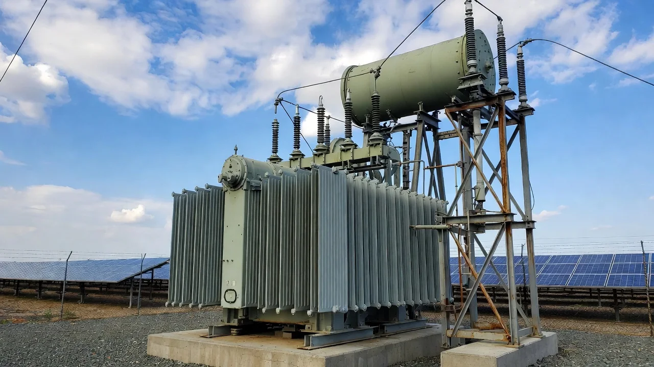
1. Why Transformer Design Matters in Utility-Scale PV
In modern utility-scale PV projects, the solar plant transformer is not merely a voltage conversion device—it is a critical interface between distributed DC generation and centralized AC grid infrastructure. As global solar energy deployment accelerates, grid codes are becoming stricter regarding harmonic distortion, reactive power support, voltage ride-through, and fault contribution.
A well-engineered solar transformer ensures:
- Stable grid connections
- Reliable power generation
- Optimal lifecycle efficiency
- Improved power quality
- Seamless integration with renewable energy storage
In grid-tied solar pv systems, transformer underperformance can lead to overheating, nuisance tripping, reduced output, and compliance penalties. Therefore, transformer specification must align with actual plant operating conditions—not just nominal power ratings.
2. Role of the Solar PV Transformer in Grid-Tied Systems
In a typical solar pv system, energy flows as follows:
PV arrays → DC combiner → DC cables → PV inverter → PV inverter transformer → MV collection system → Substation transformer → Utility grid
Key Transformer Functions:
|
Function |
Engineering Significance |
|
Voltage step-up |
Converts 400–800V inverter AC to 11kV–35kV MV |
|
Electrical isolation |
Protects the inverter & grid |
|
Harmonic buffering |
Mitigates inverter-generated harmonics |
|
Reactive power handling |
Supports grid voltage stability |
|
Fault tolerance |
Withstands short circuit stresses |
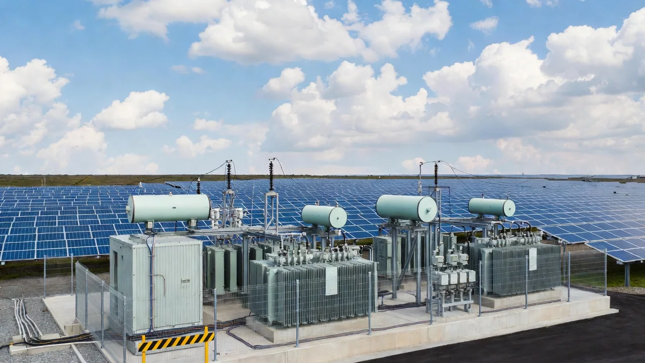
For large-scale solar plants (50–500 MW), both inverter transformers and central substation transformers must be carefully coordinated within the broader power systems architecture.
3. Transformer Sizing Based on Real Operating Conditions
3.1 Consider Solar Irradiance & Peak Demand
Unlike conventional generation, solar irradiance fluctuates daily and seasonally. Transformer loading must consider:
- Peak irradiance conditions
- Inverter clipping behavior
- Curtailment scenarios
- Future capacity expansion
Practical Example
Assume:
- PV plant capacity: 50 MW (DC)
- AC output after inverter: 45 MW
- Inverter output voltage: 690 V
- Target MV level: 33 kV
Required transformer rating:
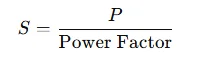
Assuming PF = 0.98:
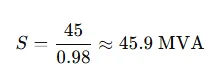
Engineering practice recommends adding a 10–15% margin:
Selected Rating: 50 MVA substation transformer
Oversizing slightly reduces thermal stress and increases lifecycle reliability.
4. Oil-Immersed vs Dry-Type Solar Transformers
|
Parameter |
Oil-Immersed |
Dry-Type |
|
Cooling |
ONAN / ONAF |
Air natural / forced |
|
Efficiency |
Higher on a large scale |
Suitable for indoor |
|
Fire Risk |
Moderate (mitigated with containment) |
Lower |
|
Maintenance |
Oil monitoring required |
Minimal |
|
Application |
Utility-scale PV |
Rooftop / commercial |
|
Cost per kVA |
Lower for large units |
Higher than 5 MVA |
For utility scale pv, oil-filled designs dominate due to better thermal performance and higher efficiency under continuous load.
5. Managing Harmonics & Power Quality
Modern PV inverters generate harmonics (5th, 7th, 11th, etc.) that affect transformer losses and heating.
Best Practices:
- Specify the K-factor rating for inverter transformers
- Use a delta-wye configuration to block triplen harmonics
- Include harmonic filters when THD > 5%
- Verify compliance with IEEE 519
|
Power Quality Factor |
Recommended Limit |
|
Voltage THD |
< 5% |
|
Current THD |
< 8% |
|
Voltage fluctuation |
< ±5% |
|
Power factor |
0.95–1.0 adjustable |
Transformer impedance must be optimized (typically 6–10%) to balance fault current limitation and voltage regulation.
6. Integration with Renewable Energy Storage
As renewable energy storage becomes standard in grid-tied plants, transformer design must consider:
- Bidirectional power flow
- Load cycling
- Short-duration peak injection
- Battery inverter harmonics
Energy storage increases transformer utilization hours, which impacts:
- Insulation aging
- Hot spot temperature
- Oil degradation rate
Lifecycle thermal modeling is recommended for hybrid solar + storage systems.
7. Environmental & Site Considerations
Transformer design must account for:
- Ambient temperature (often >45°C in desert PV sites)
- Altitude derating (>1000 m requires adjustment)
- Dust and humidity
- Seismic activity
Example Derating
At 2000m altitude:
- Cooling efficiency reduces
- Transformer capacity may require 5–8% derating
Environmental factor compensation ensures consistent power output without insulation failure.
8. Protection & Grid Code Compliance
Critical protection devices include:
- Buchholz relay
- Pressure relief valve
- Differential protection
- Overcurrent relay
- Temperature monitoring
- Online dissolved gas analysis (DGA)
Grid-tied plants must meet:
- Low Voltage Ride Through (LVRT)
- Reactive power injection requirements
- Frequency response capability
Transformer tap changers (OLTC) help regulate voltage under fluctuating solar conditions.
9. Loss Evaluation & Efficiency Optimization
Transformer losses directly impact plant profitability.
Loss Components:
|
Loss Type |
Description |
Impact |
|
No-load loss |
Core loss (constant) |
24/7 cost |
|
Load loss |
Copper loss |
Proportional to current |
|
Stray loss |
Harmonics |
Thermal stress |
Example Annual Energy Loss
Assume:
- 50 MVA transformer
- No-load loss: 45 kW
- Load loss at rated: 350 kW
- Avg loading: 60%
- Operating hours: 2,000 full-load equivalent
Load loss adjusted:
350×(0.6)2=126kW
Total average loss:
45+126=171kW
Annual energy loss:
171×2,000=342,000kWh
At $0.07/kWh:
Annual cost ≈ $23,940
Selecting higher efficiency core steel can reduce this by 8–12%.
10. Solar Transformer Design Checklist
|
Design Aspect |
Recommendation |
|
Vector group |
Dyn11 common |
|
Impedance |
6–8% typical |
|
Cooling |
ONAN minimum |
|
Insulation class |
65–80K rise |
|
Surge protection |
Arresters mandatory |
|
Monitoring |
Temperature + DGA |
|
Storage integration |
Bidirectional rated |
|
Future expansion |
10–15% capacity margin |
11. Common Engineering Mistakes to Avoid
- Undersizing based only on inverter rating
- Ignoring harmonics from PV arrays
- Failing to account for storage cycling
- Overlooking altitude and ambient derating
- Inadequate grounding design
- Neglecting grid reactive power requirements
A solar plant transformer is a strategic asset in any grid-connected solar pv system. Proper specification improves:
- Reliability
- Efficiency
- Regulatory compliance
- Lifecycle cost
- Renewable energy integration capability
As global solar power capacity continues to scale, transformer design must evolve to support:
- Higher inverter densities
- Energy storage coupling
- Advanced monitoring
- Digital substations
- Smart grid interfaces
Engineering decisions grounded in real load profiles, harmonic analysis, environmental data, and lifecycle costing will ensure robust performance in modern utility scale pv plants.
In high-growth renewable markets, transformer optimization is not just a technical requirement—it is a competitive advantage
Related Articles

Related Products
2/0 Nassa Aluminum Conductor Triplex Overhead Service Drop Cable
The 2/0 Nassa Aluminum Conductor Triplex Overhead Service Drop Cable is designed for reliable overhead electrical service connections between utility distribution lines and end users. The cable structure includes two insulated aluminum phase conductors twisted around a bare aluminum neutral messenger, providing excellent electrical performance and mechanical strength. Manufactured with high-purity aluminum and durable, weather-resistant insulation, the 2/0 Nassa Aluminum Conductor Triplex Overhead Service Drop Cable offers low electrical resistance, corrosion resistance, and long-term stability in outdoor environments. Its lightweight design allows for efficient installation while maintaining the tensile strength required for aerial applications. The cable is engineered to perform under UV exposure, wind load, and temperature variations. Comprehensive quality control and systematic testing are applied throughout production to ensure compliance with industry standards and dependable service performance.
ALUMINUM CONDUCTOR ALUMINUM CLAD STEEL REINFORCED(ACSR/AW)
Aluminum Conductor Aluminum-Clad Steel Reinforced (ACSR/AW) offers enhanced protection for overhead lines, with outer 1350 aluminum strands encircling an aluminum-clad high-strength steel core. The cladding significantly boosts corrosion resistance over traditional ACSR, ideal for marine, acidic, or high-humidity settings. Steel reinforcement provides superior mechanical properties, enabling longer spans with reduced sag and higher load capacity. Electrical conductivity from aluminum layers ensures minimal transmission losses, supporting ampacities up to 20% higher in equivalents. Adhering to IEC 61089 and ASTM B549, ACSR/AW features versatile stranding options for optimized ratios. Its design facilitates easy installation and compatibility with existing hardware. Lightweight yet robust, it lowers infrastructure costs and maintenance needs. ACSR/AW promotes sustainability through better longevity and recyclability, reducing environmental impact. Widely adopted in global utilities, it delivers reliable performance in extreme conditions, from stormy coasts to industrial hubs, making it a smart choice for future-proofing power grids.
NS75/NS90 Triplex Unjacketed Overhead Neutral Supported Cable
The NS75/NS90 Triplex Unjacketed Overhead Neutral Supported Cable provides efficient overhead power delivery for Canadian utilities. It consists of two compact 1350-H19 aluminum phase conductors insulated in black sunlight-resistant PE (NS75, 75°C) or XLPE (NS90, 90°C), twisted around a bare ACSR full neutral messenger for structural support and reduced sag. Rated 600V, with NS90 offering higher ampacity due to 90°C rating, it meets CSA C22.2 No. 129 and supports single-phase service drops or secondary distribution. The unjacketed triplex design is lightweight, easy to install, and resistant to weathering, abrasion, and chemicals. Compliant with relevant standards, the NS75/NS90 Triplex ensures cost-effective, durable performance in pole-to-building or pole-to-pole aerial setups.
4 Eskimo Aluminum Conductor Duplex Overhead Service Drop Cable
Our 4 Eskimo Duplex Service Drop Cable provides reliable overhead secondary distribution for residential applications. Consisting of two 4 AWG aluminum conductors (one phase, one neutral, 7-strand) insulated with cross-linked polyethylene (XLPE) and twisted in duplex form, it meets ASTM, ICEA, and international standards. The robust insulation resists sunlight, moisture, and mechanical damage for decades of outdoor service. Lightweight design simplifies installation with low sag and easy handling. The 4 Eskimo Duplex Service Drop Cable ensures minimal losses, high current capacity, and excellent weather performance up to 600V. Self-supporting configuration reduces pole loading. Flame-retardant options enhance safety. Commonly chosen for single-phase power delivery in subdivisions, rural homes, and temporary connections requiring safe, economical aerial bundled solutions with proven durability.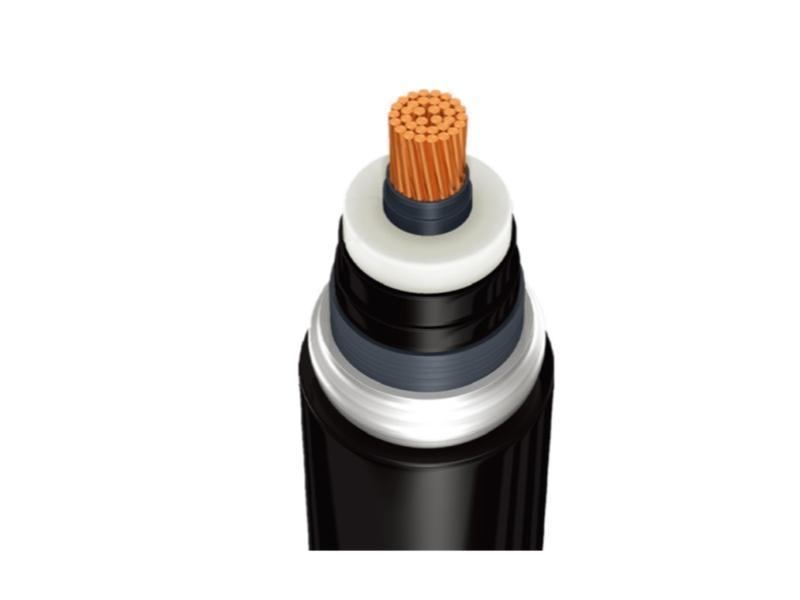
High Voltage Power Cable
NPC Electric High Voltage Power Cable is engineered for reliable transmission of electricity at voltages from 35kV to 500kV. Featuring copper or aluminum conductors, cross-linked polyethylene (XLPE) insulation, metallic screening, and a robust outer sheath, this cable minimizes losses and ensures long-term performance in demanding environments. Designed to meet international standards like IEC 60840 and IEC 62067, it offers excellent electrical properties, mechanical strength, and resistance to moisture, chemicals, and thermal stress. Whether for underground burial, submarine applications, or overhead lines, our High Voltage Power Cable delivers superior efficiency and safety. With low dielectric losses and high breakdown strength, it supports modern power grids, renewable energy integration, and industrial power distribution. Choose our cables for minimal maintenance, extended service life, and compliance with global safety norms.
6300kVA Dry Type Transformer
The NPC ELECTRIC 6300kVA Dry Type Transformer is a high-performance, heavy-duty power solution designed for large industrial and commercial applications. With a capacity of 6300kVA, it features cutting-edge dry-type insulation technology, offering superior safety, low maintenance, and extended reliability. Built to withstand demanding operating conditions, this transformer provides stable, efficient, and noise-free performance while minimizing environmental impact. Its dry-type ventilated or encapsulated construction provides zero fluid maintenance, no spill/leak risks, and suitability for extreme high-density loads, space-limited, or environmentally restricted high-power applications.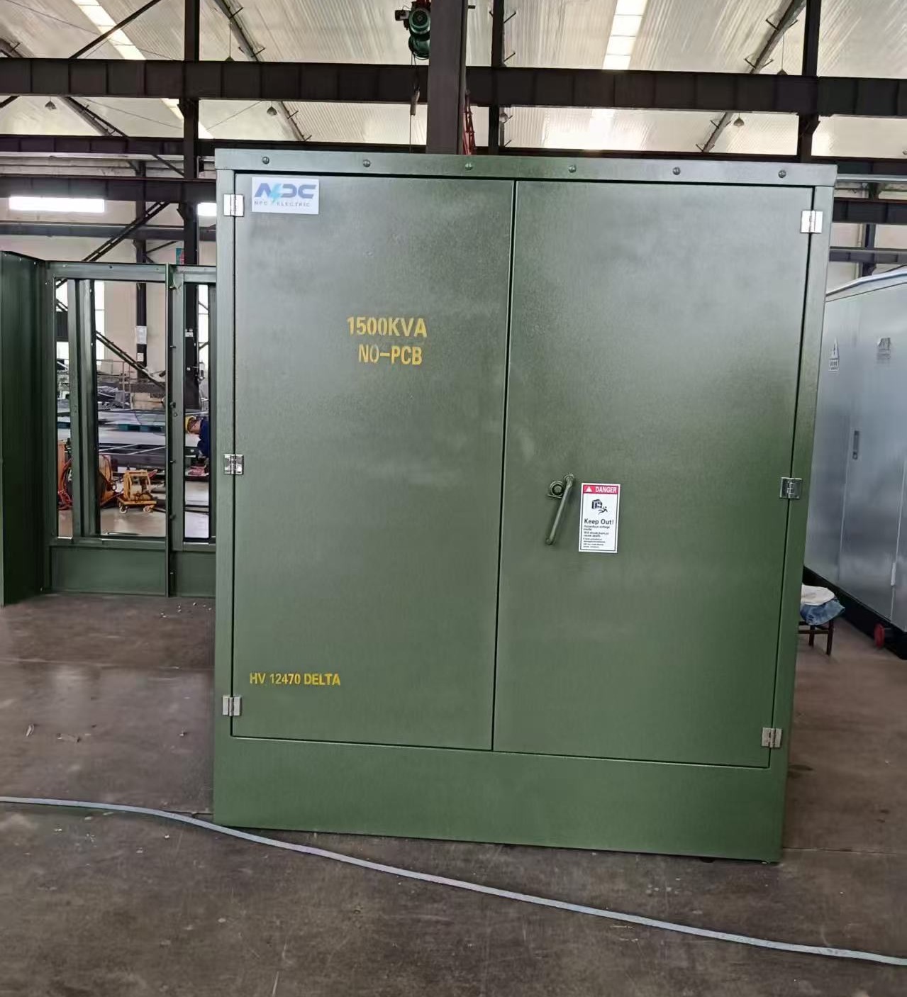
1500kVA Radial Feed Pad Mounted transformer DOE 2016
The 1500kVA Radial Feed Pad-Mounted Transformer is designed for reliable medium-voltage power distribution in utility, commercial, and renewable energy (solar) applications. Engineered to comply with IEEE C57.12.34, C57.12.24, C57.12.00, and DOE 2016 efficiency standards, this pad-mounted transformer is ideal for step-down applications from 12.47kV to 480/277V. Standard features include mineral oil or FR3 natural ester fluid (ONAN cooling), aluminum or copper windings, primary voltage 13.8kV (13800V Delta or 12470GrdY/7200 common), secondary 480Y/277V (or 208Y/120V, custom options), BIL 95kV HV / 30kV LV, impedance 5.75–7.0% (±7.5%), ±2×2.5% taps, radial-feed dead-front design with three high-voltage bushings (H1, H2, H3), bayonet fuses + partial-range current-limiting fuses, load-break switch (optional), lightning arresters, pressure relief valve, oil level/temperature gauges, and ANSI 70 gray (or Munsell green) finish.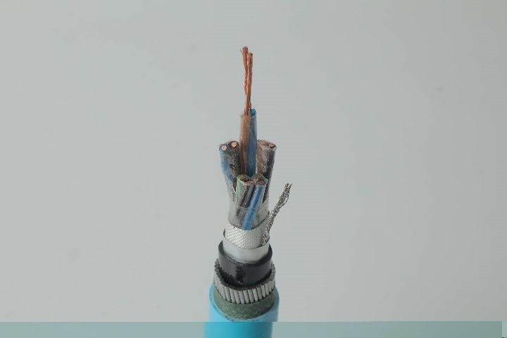
Instrumentation Cables—XLPE Insulated, Overall Screened ,Unarmoured PVC Sheathed Cables(CU/XLPE/OSCR/PVC)
Instrumentation cables come in twisted pairs, triads, and quads, depending on the customer’s applications; twisting reduces any electromagnetic interference by reducing the chances of electrical voltages and currents being induced in the conductor. Individual and overall screening are also applied in instrumentation cables to optimize the signal transferred and further reduce any electromagnetic interference. Screening of pairs, triads, or quads also includes a drain wire earthed to the ground, which ensures a noise-free signal transmission. Depending on the application, instrumentation cables can be insulated with PVC or XLPE; the cables can be armoured or unarmoured. The sheathing materials can be of PVC, LSZH, or PE. The cables can have additional flame retardant or flame retardant properties, and they can be manufactured with special protections such as lead sheaths, or DRYLAM or AIRBAG technology.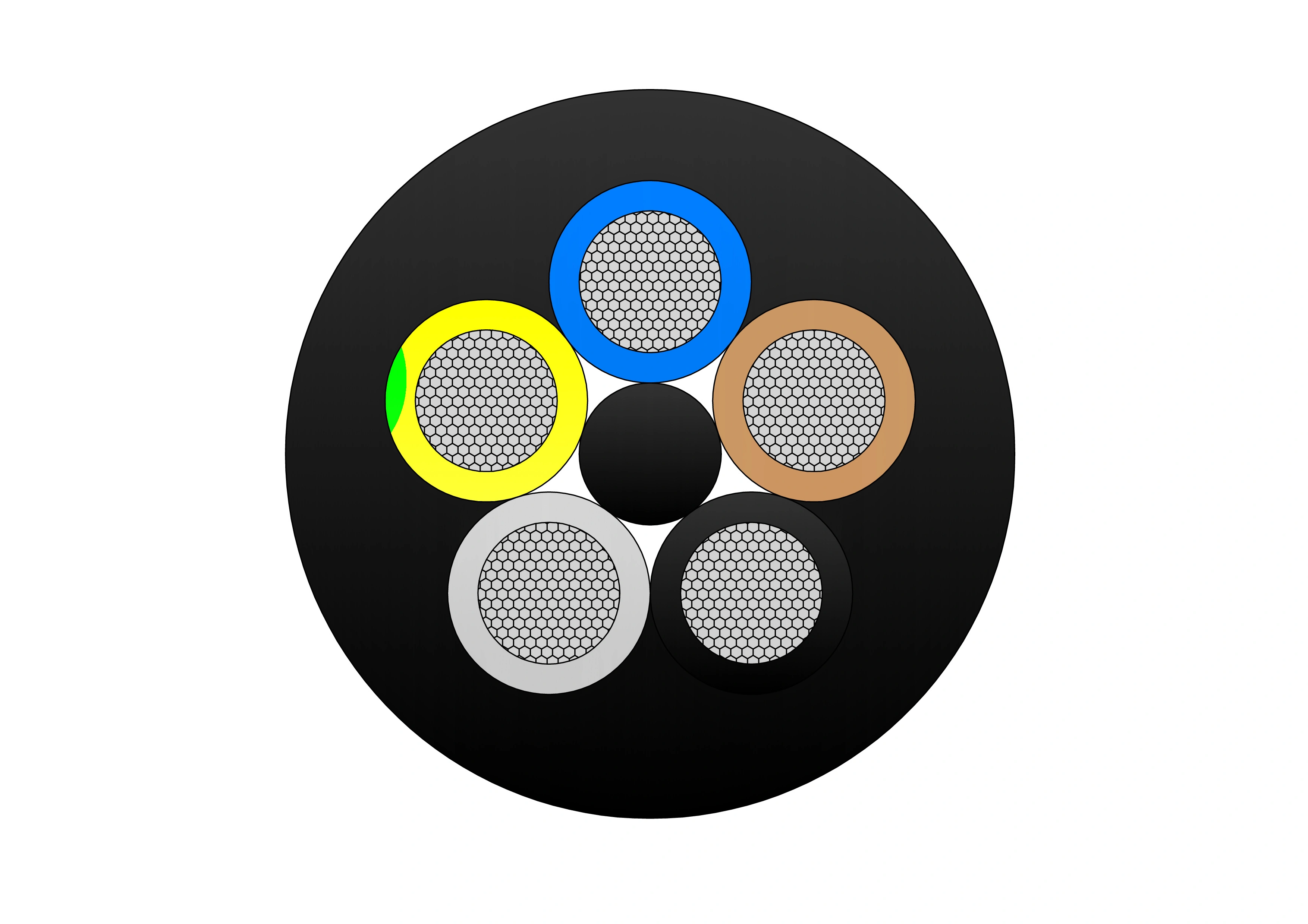
(N)TSCGEWOU 3.6/6kV, 6/10kV, 8.7/15kV and 12/20kV ZH Cable
The (N)TSCGEWOU 3.6/6kV, 6/10kV, 8.7/15kV, and 12/20kV ZH Cable is a halogen-free flexible medium voltage power cable designed in accordance with VDE 0250 standards for heavy-duty applications. It features Class 5 tinned copper conductors, EPR insulation, semi-conductive layers, and a copper braided earth conductor, with an inner and outer halogen-free polyurethane sheath that delivers excellent flame retardancy, low smoke emission, and high mechanical durability. Ideal for draglines, shovels, dredges, and drills in opencast mining or other extreme environments, this cable is suitable for both indoor and outdoor use where fire safety and robust performance are critical. Compliant with DIN VDE 0250 and IEC standards (IEC 60754, IEC 61034), it offers high flexibility, torsional strength, and EMC protection across voltage ranges. The (N)TSCGEWOU ZH is ideal for safe MV power delivery to mobile machinery such as shearers, tunnel boring equipment, and conveyors in underground mining where low-smoke, low-toxicity performance is essential.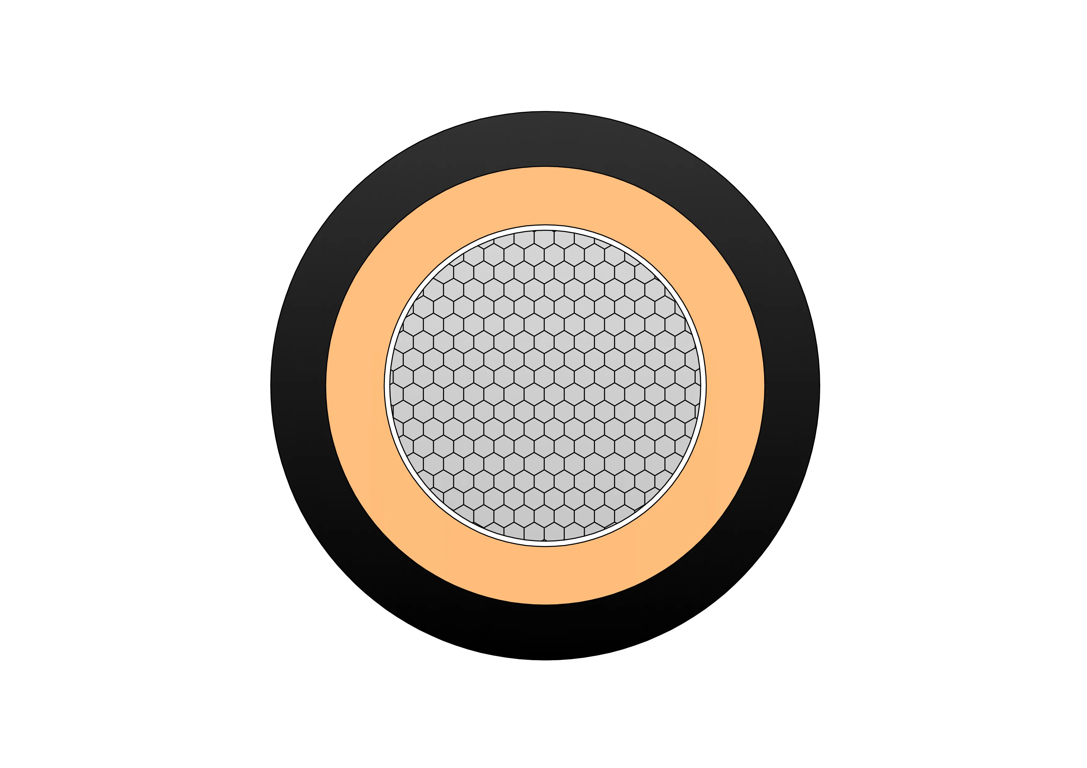
Coil End Lead Type 4 BS 6195 Cable
The Coil End Lead Type 4 BS 6195 Cable is a premium, highly flexible high-temperature lead wire engineered for demanding coil and transformer applications. It features fine-stranded tinned copper conductors for superior conductivity and corrosion resistance, high-purity silicone rubber insulation providing excellent dielectric strength, exceptional heat resistance (continuous 180°C, short-term 220°C), and outstanding flexibility even in cold conditions. Compliant with BS 6195 Type 4 standard, it offers flame retardancy, ozone resistance, and long-term thermal stability without cracking or hardening. The cable is lightweight, easy to strip, and suitable for tight bending radii in coil winding, motor connections, and transformer lead-outs. The Coil End Lead Type 4 BS 6195 Cable ensures reliable performance in high-heat environments, reducing downtime and enhancing safety in electrical equipment manufacturing and repair.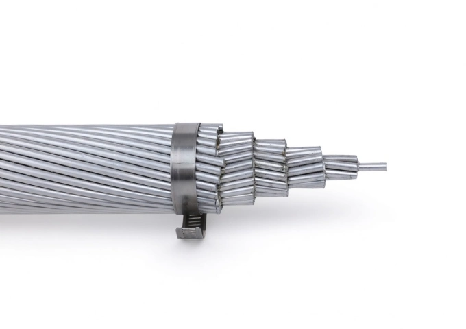
1033.5 MCM Bluebell AAC All Aluminum Bare Conductor Cable
The 1033.5 MCM Bluebell AAC Cable represents premium All Aluminum Conductor technology for overhead power applications. Built with 37 strands of high-conductivity 1350-H19 aluminum, this bare conductor delivers an optimal balance of electrical efficiency and mechanical robustness. With a 1.170-inch diameter, 17,900 lbs breaking strength, and 1033 amps ampacity, the Bluebell AAC offers low DC resistance of 0.0167 ohms per 1000 ft at 20°C and a weight of 970.3 lbs per 1000 ft. This design minimizes sag while providing excellent corrosion resistance for extended outdoor service. Manufactured to meet ASTM B-230 and B-231 standards, the 1033.5 MCM Bluebell AAC Cable undergoes extensive quality testing from raw materials through finished product. It is the ideal solution for new installations and upgrades in transmission and distribution systems that demand lightweight, high-conductivity bare aluminum conductors.
4 Strombus Aluminum Conductor Triplex Overhead Service Drop Cable
4 Strombus Aluminum Conductor Triplex Overhead Service Drop Cable is designed for reliable overhead power distribution from utility lines to service entrances of residential, commercial, and light industrial buildings. This cable consists of two insulated phase conductors and one bare or insulated neutral messenger made from high-purity aluminum, ensuring excellent conductivity, reduced weight, and long service life. The 4 Strombus Aluminum Conductor Triplex Overhead Service Drop Cable is manufactured using precision stranding and advanced insulation extrusion technology, providing stable electrical performance and strong mechanical strength. The insulation material offers excellent resistance to weathering, UV radiation, moisture, and temperature fluctuations, making the cable suitable for long-term outdoor installation. To guarantee consistent quality, the 4 Strombus Aluminum Conductor Triplex Overhead Service Drop Cable undergoes a comprehensive testing system covering raw materials, production processes, and finished products. Each stage follows standardized testing procedures to ensure compliance with international standards and utility requirements. This cable is an ideal solution for cost-effective, safe, and efficient overhead service drop applications.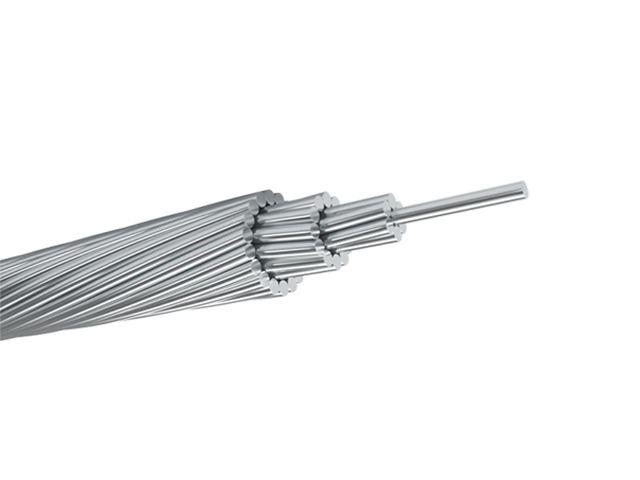
FLINT AAAC Conductor Cable
FLINT AAAC (All Aluminum Alloy Conductor) cables are manufactured in accordance with ASTM B399 and IEC 61089 standards, offering excellent strength, conductivity, and corrosion resistance. With 750 mm² nominal area and 37-strand design, it uses heat-treated aluminum-magnesium-silicon alloy (6201-T81) for enhanced strength (295 MPa min) and conductivity (53% IACS min). Meeting ASTM B398, B399, IEC 61089, and BS EN 50182 standards, this cable handles ampacity up to 1150A at 75°C and voltages up to 33kV. The all-alloy construction avoids bimetallic corrosion, providing better resistance in harsh conditions than ACSR. Reduced weight minimizes sag and installation expenses, supporting longer spans. The Flint AAAC Conductor Cable delivers low electrical losses, high mechanical endurance, and excellent weather tolerance. Flame-retardant variants available. Perfect for urban grids, renewable projects, and coastal setups, it provides cost-effective, low-maintenance power delivery in overhead applications globally, excelling in reliability and lifespan over conventional conductors.
2/0 Triton Aluminum Conductor Triplex Overhead Service Drop Cable
The 2/0 Triton Aluminum Conductor Triplex Overhead Service Drop Cable is engineered for reliable overhead electrical service from utility distribution lines to residential and commercial buildings. The cable consists of two insulated aluminum phase conductors twisted around a bare aluminum neutral messenger, providing balanced electrical performance and strong mechanical support. Manufactured from high-purity aluminum and weather-resistant insulation compounds, the 2/0 Triton Aluminum Conductor Triplex Overhead Service Drop Cable delivers low electrical resistance, excellent corrosion resistance, and long-term durability in outdoor environments. Its lightweight construction simplifies handling and installation while maintaining the tensile strength required for aerial service. The cable is designed to perform under UV exposure, wind loading, and temperature variation. Comprehensive quality control and systematic testing are applied throughout production to ensure compliance with utility standards and dependable field performance.
138kV / 140kV / 150kV Three-Phase Oil-Immersed Power Transformer
The 138kV / 140kV / 150kV Three-Phase Oil-Immersed Power Transformer is designed to serve high-voltage transmission and substation applications requiring dependable energy transfer and long-term operational stability. Its design emphasizes electrical reliability, structural strength, and efficient thermal management to support continuous service under varying grid loads. The transformer employs a refined magnetic circuit and carefully engineered winding structure to maintain voltage accuracy while minimizing operational stress. An oil-immersed insulation and cooling system ensures effective heat dissipation and insulation integrity throughout extended operating cycles. Built for outdoor installation, the transformer is capable of withstanding environmental exposure, electrical fluctuations, and mechanical demands associated with modern high-voltage networks. It is suitable for utility-scale projects where safety, efficiency, and durability are essential performance criteria.Welcome your inquiry
Honesty, Integrity, Frugality, Activeness and Passion