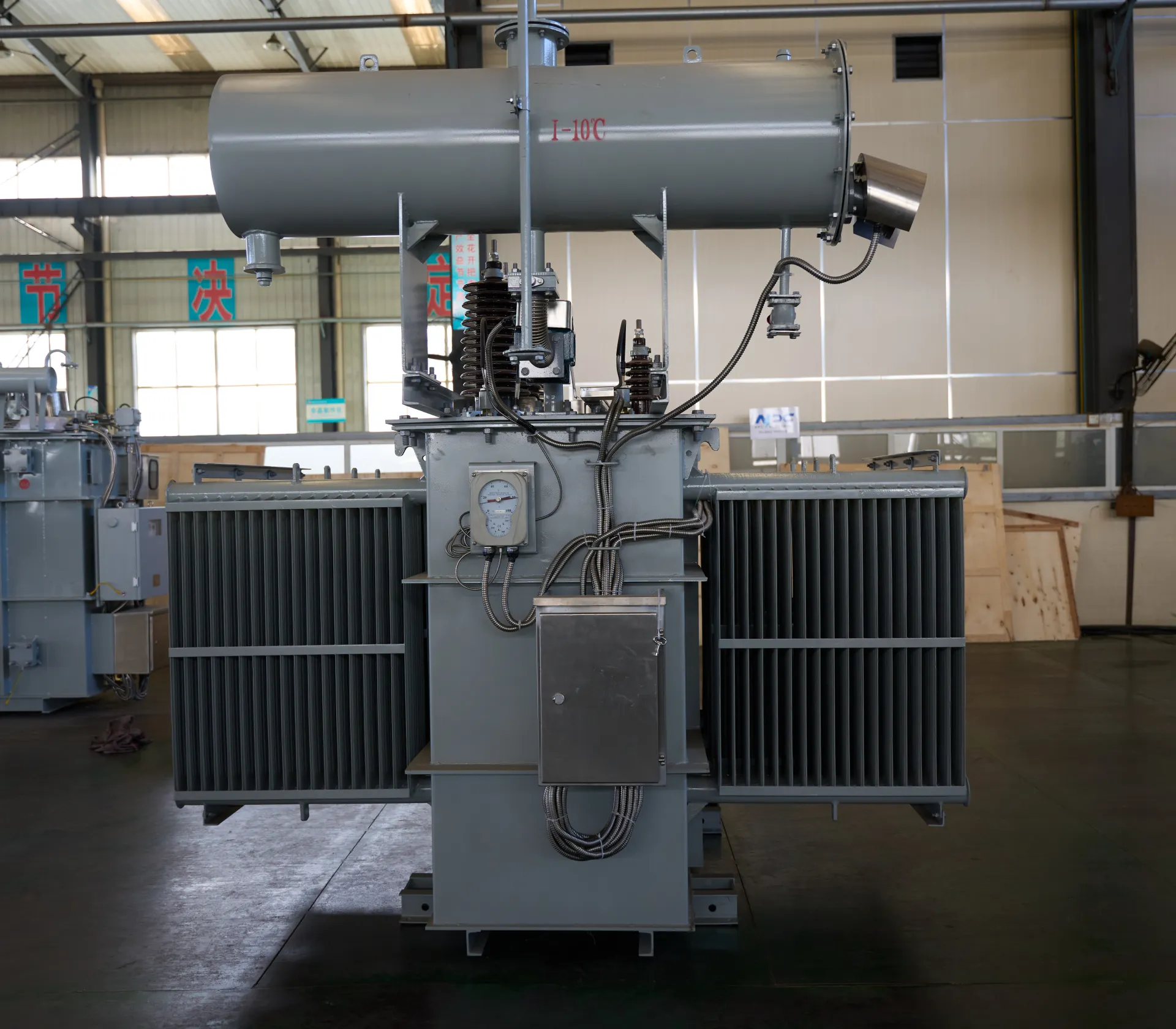
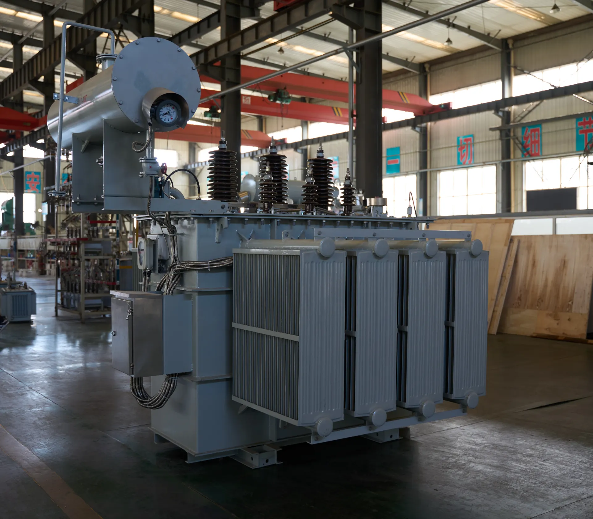
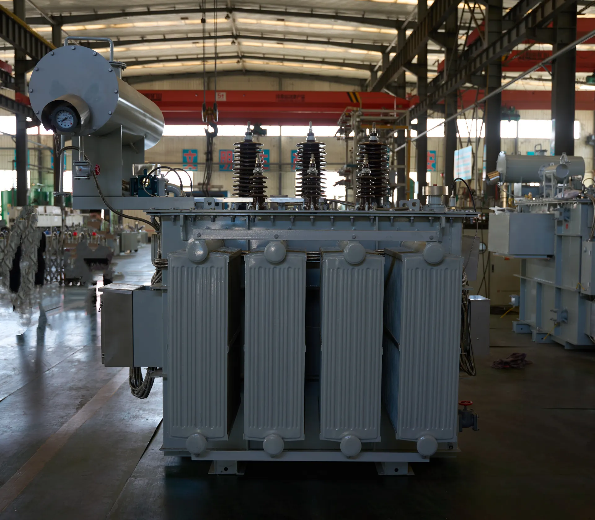
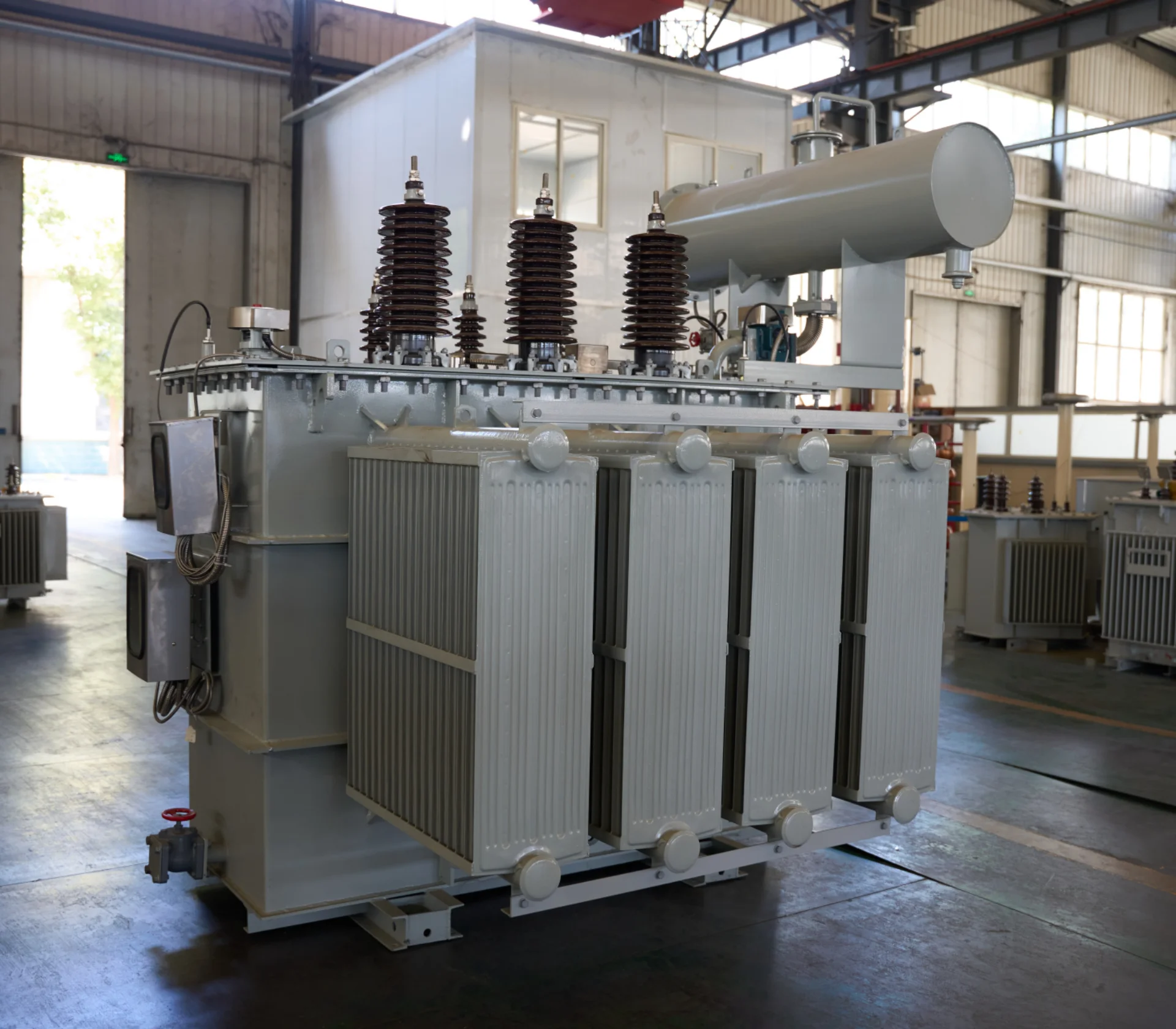


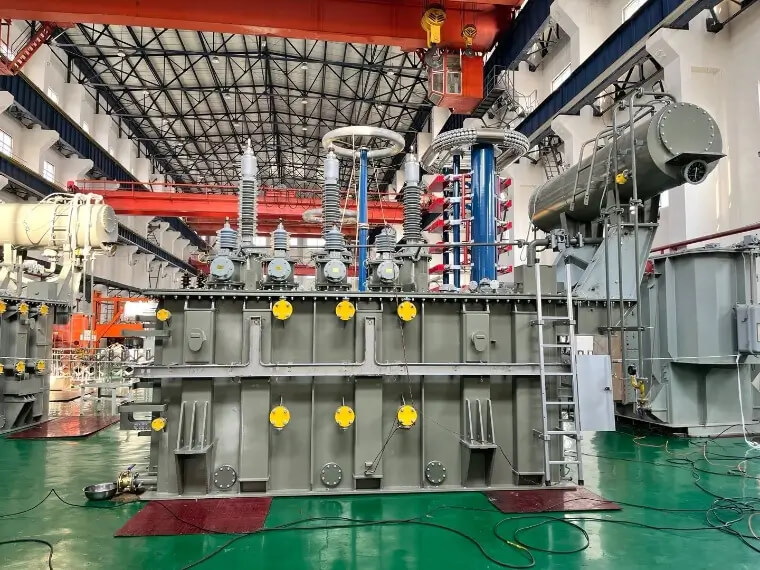
40kV 50MVA Oil Immersed Three-Phase MV&HV Power Transformer Copper
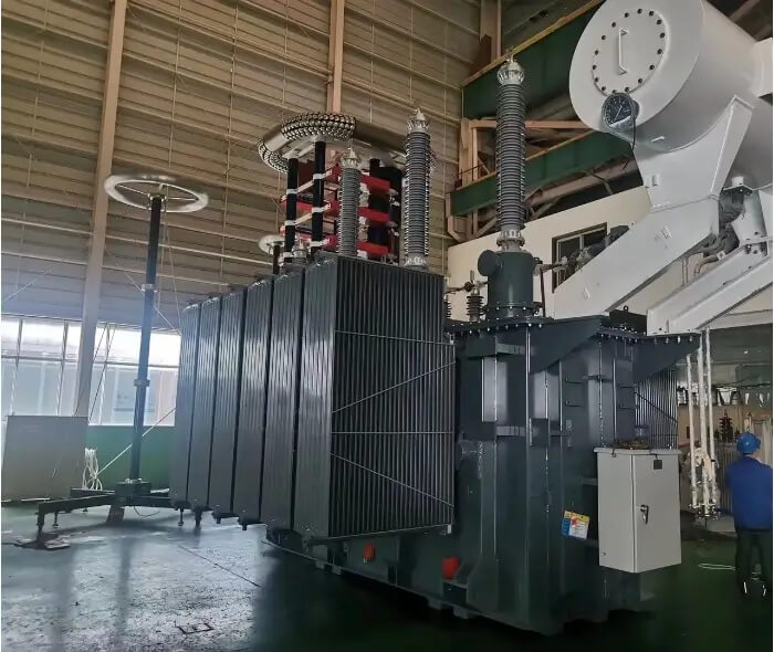
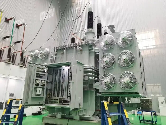
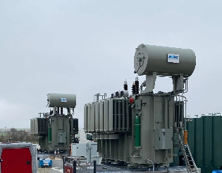
The 40kV 50MVA Oil Immersed Three-Phase MV&HV Power Transformer Copper is engineered for large-scale transmission and industrial substations. Equipped with high-purity copper windings, ONAN/ONAF cooling, and ±8×1.25% on-load tap changer, it achieves ultra-low losses (S13/S14 series). Fully compliant with IEC 60076 and GB/T 1094, it withstands 200 kV lightning impulse and PD <10 pC. Robust corrugated-fin tank with detachable radiators ensures excellent thermal performance under continuous heavy load. Typical voltages: 40±8×1.25%/11kV or 40/6.3kV. Vacuum oil filling and nitrogen sealing guarantee 35+ years of reliable, maintenance-free operation in harsh environments. Trusted by utilities and EPC contractors worldwide.
- Primary Voltage Ratings 35kV, 34.5kV, 33kV, 46kV or others
- Secondary Voltage Ratings 13.8kV 6kV 10kV or others
- H.V. Tap Range ±8×1.25% or others
- Type Oil-immersed power transformer
- BIL 40kV
- Standards IEEE, ANSI, NEMA, IEC, CE
- Application railway traction systems, data centers, and port heavy-load power supply
- Power Rating 50MVA
- Certificate UL, CESI, IEEE
- Cooling Method ONAN/ONAF
- Oil Mineral Oil or FR3
- Opeartion Step Down & Step Up
Technical Specifications
Customization Optional
Packing and Shipping
Manufacturer Test
Routine Testing
Application
Technical Specifications
40kV 50MVA Oil Immersed Three-Phase MV&HV Power Transformer Copper
Technical Specifications
Accessories
| Rated Power | 50MVA | |
| Rating Primary Voltage | 40 kV | |
| Secondary Voltage |
6.6kV 10kV 13.8kV Customized |
|
| Frequency | 50/60Hz | |
| Vector Group | Dyn11, Yyn0, Dyn5 | |
| Winding Material | Aluminum/Copper | |
| Efficiency | As IEEE, Doe 2016, CAS Std or Customized | |
| Impedance Voltage | Nominal 2% or Customized 1.1 - 5.75% | |
| Altitude | ≤1,000m or Customized | |
| Color | ANSI 70 Light gray/Munsell 7GY3.29/1.5 or customized, etc | |
| Tank material | Mild Steel, 304 Stainless Steel | |
| HV Bushing |
| LV Bushing |
| Tap changer |
| Oil level gauge |
| Oil temperature indicator |
| Pressure relief device |
| Pressure vacuum gauge |
| Lifting hook for complete transformer |
| Name plate |
| Radiators |
| Oil upper filtering valve |
| Oil drain valve with 3/8" sampler |
Customization Optional
40kV 50MVA Oil Immersed Three-Phase MV&HV Power Transformer Copper
Clients may select 40–63MVA capacity range, full copper or hybrid windings, S13/S14 ultra-low-loss core, voltage ratios 40±8×1.25%/11kV, 40/33kV, 40/13.8kV or tertiary winding. Tap changer: off-circuit ±5% or on-load ±10×1%. Vector group YNd11, Dyn11, or custom. Cooling options include ONAN, ONAF auto-controlled fans, or ODAF.
Extra features: built-in CT/PT bays, fiber-optic temperature monitoring, online DGA & oil regeneration, sudden pressure relay, SCADA-ready RTU, IP55/65 enclosure, seismic design up to 0.5g, high-altitude >4000 m compensation, and C5-M marine anti-corrosion coating. All configurations remain IEC 60076 compliant with type/special test reports provided.
Packing and Shipping
40kV 50MVA Oil Immersed Three-Phase MV&HV Power Transformer Copper
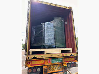
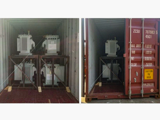
Immediately after successful FAT and client sign-off, the 40kV 50MVA transformer (~105–115 tons) undergoes final vacuum dehydration to ≤1 mbar for 72 hours, followed by hot-oil spray and circulation until oil moisture ≤5 ppm and dielectric strength ≥75 kV/2.5 mm. The tank is then filled with ultra-dry nitrogen (99.999 %) to 0.035–0.045 MPa positive pressure and sealed with double valves. All openings are fitted with blind flanges and silica-gel breathers. A calibrated digital pressure gauge with data logger is installed on the conservator pipe to continuously record internal pressure throughout the entire transportation period, ensuring any leakage is detected instantly. Nitrogen certificates and 90-day pressure trend reports are provided with shipping documents.
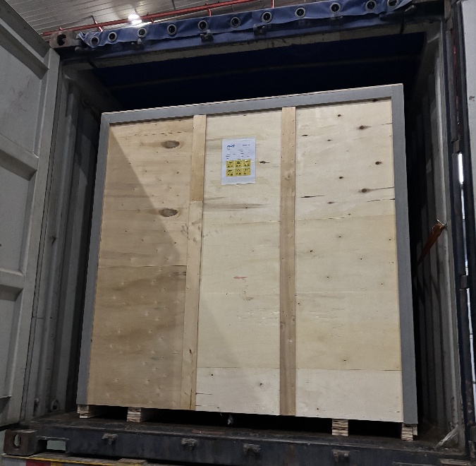
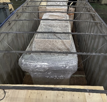
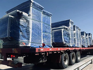
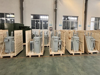
All 40 kV porcelain bushings (HV & LV), neutral bushing, conservator tank, detachable radiator banks (16–20 panels), OLTC diverter switch chamber, cooling fans with motors, marshalling box, Buchholz relay, oil level indicators, winding/oil temperature gauges, sudden pressure relay, and pressure relief device are professionally dismantled by senior technicians. Each component is wrapped in VCI anti-corrosion film, placed in custom-designed IPPC-fumigated marine-plywood crates with minimum 50 mm high-density foam lining on all six sides, and packed with 500 kg of silica-gel desiccant per crate. Four high-precision Tell-Tale shock recorders (3-axis, ±200 g) and two electronic tilt indicators (±30°) are fixed on each crate. All crates are labeled in English/Chinese with part numbers, transformer serial number, gross/net weight, and “Extremely Fragile – Handle with Care” warnings.
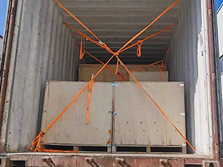
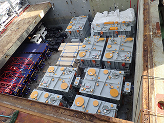
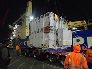
Inland haulage is executed exclusively by licensed 32–40 axle hydraulic modular trailers (Nicolas/Scheuerle) with full route survey, police escort, and height ≤5.0 m. Ocean freight is break-bulk under-deck or on 80 ft heavy-lift flat-rack containers (CCS/DNV-GL approved). Lashing and seafastening follow DNV-GL 2.7-1 rules using Φ36–Φ40 mm steel wire ropes, 100-ton turnbuckles, and anti-slip mats. Complete documentation package includes detailed packing list, 110 % all-risk marine cargo insurance (ICC A), Form A/E origin certificate, IPPC fumigation certificate, nitrogen pressure & trend report, shock recorder baseline data, installation manual, and third-party loading survey report. These uncompromising measures ensure every 40kV 50MVA transformer arrives in perfect, ready-to-energize condition anywhere in the world.
All 40 kV porcelain bushings (HV & LV), neutral bushing, conservator tank, detachable radiator banks (16–20 panels), OLTC diverter switch chamber, cooling fans with motors, marshalling box, Buchholz relay, oil level indicators, winding/oil temperature gauges, sudden pressure relay, and pressure relief device are professionally dismantled by senior technicians. Each component is wrapped in VCI anti-corrosion film, placed in custom-designed IPPC-fumigated marine-plywood crates with minimum 50 mm high-density foam lining on all six sides, and packed with 500 kg of silica-gel desiccant per crate. Four high-precision Tell-Tale shock recorders (3-axis, ±200 g) and two electronic tilt indicators (±30°) are fixed on each crate. All crates are labeled in English/Chinese with part numbers, transformer serial number, gross/net weight, and “Extremely Fragile – Handle with Care” warnings.
Inland haulage is executed exclusively by licensed 32–40 axle hydraulic modular trailers (Nicolas/Scheuerle) with full route survey, police escort, and height ≤5.0 m. Ocean freight is break-bulk under-deck or on 80 ft heavy-lift flat-rack containers (CCS/DNV-GL approved). Lashing and seafastening follow DNV-GL 2.7-1 rules using Φ36–Φ40 mm steel wire ropes, 100-ton turnbuckles, and anti-slip mats. Complete documentation package includes detailed packing list, 110 % all-risk marine cargo insurance (ICC A), Form A/E origin certificate, IPPC fumigation certificate, nitrogen pressure & trend report, shock recorder baseline data, installation manual, and third-party loading survey report. These uncompromising measures ensure every 40kV 50MVA transformer arrives in perfect, ready-to-energize condition anywhere in the world.
32
32 years of industry experience
Manufacturer Test
40kV 50MVA Oil Immersed Three-Phase MV&HV Power Transformer Copper
Progress Test
Throughout the manufacturing cycle, the 40kV 50MVA transformer undergoes strict, fully documented and client-witnessable Progress Tests at four key stages to guarantee zero defects before FAT.
Stage 1 – Core & Coil Assembly Winding DC resistance measurement on all HV/LV taps, insulation resistance between windings and ground (PI ≥ 3.0 after 130 °C pre-drying), core grounding current <100 mA, preliminary no-load loss and magnetizing current check, turns ratio on sample coils, and inter-winding capacitance verification.
Stage 2 – Pre-Tanking Voltage ratio at principal and extreme taps (deviation ≤ ±0.5 %), vector group confirmation (YNd11/Dyn11), polarity, zero-sequence impedance, magnetic balance, and low-voltage excitation test to verify winding integrity and core performance.
Stage 3 – After Vapor-Phase Drying & Vacuum Oil Filling Final insulation resistance (>20,000 MΩ at 40 °C), dielectric dissipation factor tanδ ≤ 0.0030 (20 °C), partial discharge <10 pC at 1.5Um/√3, oil breakdown voltage ≥75 kV/2.5 mm, moisture in oil <8 ppm, and dissolved gas analysis (DGA) baseline.
Design Tests
All transformer will be test after finished the production, test items as below:
♦ Insulation Power Factor
♦ Ratio, Polarity, and Phase Relation
♦ Winding Resistance
♦ Impulse Tests
♦ On load Loss Test
♦ No Load Loss Test
♦ Leak Test
♦ DC Insulation Resistance Test
♦ Transformer Turns Ratio/TTR (All Tap Voltages)
♦ Impedance Voltage & Load Loss (Rated Voltage)
♦ Polarity, 1-Ph / Phase Relation, 3-Ph (Rated Voltage)
♦ Excitation & No-Load Loss (Rated Voltage)
♦ Applied Voltage
♦ Induced Voltage
♦ Lightning Impulse
♦ Insulation Resistance (Rated Voltage)
♦ Temperature Rise
♦ Dielectric Withstand (Hipot)
Transformer Factory Acceptance Test
The FAT is executed in strict adherence to IEC 60076-1/3/11, GB/T 1094, and project specifications, with full client/third-party witness (SGS/BV/TÜV).
Key tests include:
- Winding resistance at all OLTC taps (corrected to 75 °C)
- Voltage ratio, polarity, and phase displacement at principal/extreme taps (≤ ±0.5 % deviation)
- Vector group verification (YNd11/Dyn11) and magnetic balance
- No-load loss/current at 90 %, 100 %, 110 % rated voltage
- Load loss and short-circuit impedance at 75 °C/rated current
- Separate-source applied voltage withstand
- Induced overvoltage with PD (<10 pC at 1.5Um/√3, <5 pC at Um/√3)
- Lightning impulse full/chopped wave (200–230 kV peak on 40 kV side)
- Insulation resistance, PI (≥ 3.0), tanδ ≤ 0.003, oil BDV ≥ 75 kV
Official protocol with raw data is signed, confirming 100 % readiness for 40 kV grid service.
Routine Test - DC Insulation Resistance Test
Purpose of Testing
The purpose of DC insulation resistance testing is to measure the insulation resistance of a device by applying a DC voltage, thereby evaluating the health of the insulation material and the voltage withstand capability of the electrical device. This test helps detect potential insulation aging, moisture or damage, preventing electrical failures in the device.
Testing Equipment
Insulation resistance tester (e.g. Megger, Fluke, Hioki, Klein Tools, etc.)
Voltage source (usually 500V, 1000V, 2500V, or customized according to customer requirements)
Temperature and humidity meter (used to record the ambient temperature and humidity during the test to ensure that the test conditions meet the standard requirements.)
Voltage source (usually 500V, 1000V, 2500V, or customized according to customer requirements)
Temperature and humidity meter (used to record the ambient temperature and humidity during the test to ensure that the test conditions meet the standard requirements.)
Pre-Test Preparation
Make sure the device is properly grounded and fully discharged to prevent residual charge in the device from affecting the test results.
Perform the test under suitable environmental conditions. It is recommended to have a relative humidity below 75%, no rain, and a temperature range of 20-30°C to avoid moisture or temperature fluctuations affecting the test results.
Perform the test under suitable environmental conditions. It is recommended to have a relative humidity below 75%, no rain, and a temperature range of 20-30°C to avoid moisture or temperature fluctuations affecting the test results.
Test Progress
Connect the Test Instrument:
Connect an insulation resistance tester to the high voltage terminal of the device under test and to ground.
Apply Test Voltage:
Select an appropriate test voltage based on the rated voltage of the equipment .
Connect an insulation resistance tester to the high voltage terminal of the device under test and to ground.
Apply Test Voltage:
Select an appropriate test voltage based on the rated voltage of the equipment .
Measure and Record
Start the test and record the following parameters:
Insulation resistance value (MΩ)
Applied voltage
Ambient temperature and humidity during testing
Insulation resistance value (MΩ)
Applied voltage
Ambient temperature and humidity during testing
Temperature Correction
The measured insulation resistance values are corrected to a reference temperature (usually 20°C) for accurate evaluation.
Repeat Testing (if necessary)
Measure different windings (high voltage, medium voltage, low voltage) or each bushing separately, and conduct comparative analysis to ensure the insulation status of all parts.
Evaluation Criteria (Reference)
Insulation resistance ≥ 1000 MΩ (excellent)
500 MΩ ≤ Insulation resistance < 1000 MΩ (good)
100 MΩ ≤ Insulation resistance < 500 MΩ
Insulation resistance < 100 MΩ
500 MΩ ≤ Insulation resistance < 1000 MΩ (good)
100 MΩ ≤ Insulation resistance < 500 MΩ
Insulation resistance < 100 MΩ
Observing electrical behavior
Observe the electrical behavior of the device under test to ensure that there are no abnormal currents, arcing, noise, or electrical faults.
*These comprehensive tests ensure that each transformer meets performance standards and operates
reliably under various conditions.
Application
It supports continuous 150% overload and repeated short-circuit events with noise levels below 65 dB and a design life exceeding 35 years. It is the preferred core equipment for utilities and industrial users seeking safe, energy-efficient, and highly reliable power delivery.


Technical Advantages
● 30+ years of manufacturing experience
● ISO and UL certified production
● Customized cable and transformer solutions


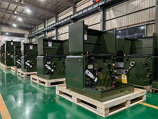
Product Packaging
Transformers Packaging (1)
Transformers Packaging (2)
Transformers Packaging (3)
Transformers Packaging (4)
Transformers Packaging (5)
Transformers Packaging (6)
Transformers Packaging (7)
Transformers Packaging (8)
Related Products
115kV 35MVA Three-Phase Oil-Immersed Power Transformer
The 115kV 35MVA Three-Phase Oil-Immersed Power Transformer is designed for reliable and efficient operation in high-voltage transmission and substation applications. Built with high-permeability silicon steel cores and precision-wound copper conductors, it delivers low losses, strong short-circuit withstand capability, and excellent thermal stability. The oil-immersed cooling system ensures effective heat dissipation, enabling continuous operation under heavy-load conditions. A robust tank structure, advanced insulation system, and outdoor-rated protection make the transformer suitable for harsh environmental conditions. Manufactured in accordance with IEC, IEEE, and ANSI standards, this transformer is widely used in utility substations, industrial power systems, and regional transmission networks where long service life, stable voltage regulation, and high operational reliability are critical.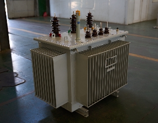
2500kVA Oil Immersed Transformer
NPC ELECTRIC's 2500kVA oil-immersed transformer is designed with international advanced technology and complies with international standards such as IEC, ANSI, and ISO. It has high efficiency, low noise, and excellent thermal stability. This transformer is widely used in power transmission and distribution systems to ensure a stable and reliable power supply. High-strength windings and robust mechanical construction enhance short-circuit withstand capability and thermal endurance. With reliable voltage regulation and low operational noise, this transformer is well-suited for industrial plants, infrastructure projects, and utility substations requiring a dependable high-capacity power supply.
1250kVA Oil Immersed Transformer
NPC ELECTRIC's 1250kVA oil-immersed transformer adopts advanced design and manufacturing technology and complies with international power equipment standards (such as IEC, ANSI, IEEE, etc.). Its high-quality materials and strict quality control ensure the long-term reliability and safety of the equipment. The transformer has high efficiency and stable power transmission performance and is widely used in industrial, commercial, and power systems. With low operating noise and reliable voltage regulation, the transformer is well suited for industrial facilities, commercial complexes, and utility distribution networks.
121kV Oil-Immersed High-Voltage Power Transformer
The 121kV Oil-Immersed High-Voltage Power Transformer is designed to provide stable, efficient, and long-term power transformation for transmission networks and high-voltage substations. Utilizing high-quality silicon steel cores and precision-wound copper conductors, the transformer achieves low no-load losses, strong short-circuit withstand capability, and excellent thermal stability. The oil-immersed insulation and cooling system ensures effective heat dissipation, supporting continuous operation under heavy-load and fluctuating grid conditions. Its reinforced tank structure, advanced insulation system, and outdoor-rated protection design enable reliable performance in harsh climates and demanding environments. Manufactured in accordance with IEC, IEEE, and ANSI standards, this transformer is widely applied in utility grids, industrial power systems, and infrastructure projects requiring high reliability, safety, and long service life.
500kVA Three Phase Pad Mounted Transformer
The 500kVA three-phase pad transformer is an efficient and sturdy power equipment designed for commercial, industrial and distribution systems. It has a compact design and a protective casing that meets NEMA 3R or higher standards. It is suitable for various outdoor environments and can effectively resist external factors such as weather, dust and moisture. It can meet the power needs of different regions and has a variety of optional functions, such as load regulation and temperature control systems, to further improve its operating efficiency and safety. The built-in protection device can effectively prevent overload, short circuit and other faults to ensure the safe and reliable operation of the power system.
100kVA Completely self-protected(CSP) Single Phase Pole Mounted Transformer
100kVA CSP Single Phase Pole Mounted Transformer is a highly efficient and reliable solution designed for single-phase power distribution in residential, commercial, and light industrial applications. It features integrated self-protection systems, including overload, short-circuit, and over-voltage protection, ensuring automatic disconnection in the event of faults to safeguard both the transformer and connected equipment. With its pole-mounted design, it offers space-saving installation and is suitable for both urban and rural environments. This transformer delivers high operational efficiency with minimal energy loss and is built to withstand harsh weather conditions, ensuring long-lasting and reliable performance. It is the ideal choice for providing safe and stable single-phase power in diverse applications.FAQ From Customers
-
What is a Transformer?A transformer is an electrical device used to change the voltage of alternating current (AC). It works on the principle of electromagnetic induction, converting high-voltage current into low-voltage current or low-voltage current into high-voltage current. Transformers are widely used in power transmission, distribution systems, and various electronic devices.
-
What are the main uses of a transformer?The main use of a transformer is voltage conversion. Transformers are used in power transmission systems to help transfer electricity from power plants to consumers. In addition, transformers are also used in electronic devices such as chargers, televisions, power adapters, etc., to adjust the voltage to meet the requirements of different devices.
-
Do you have UL listed?Yes, our transformer has UL listed. We have exported to America many pad mounted transformer,substation transformer and HV.
Welcome your inquiry
Honesty, Integrity, Frugality, Activeness and Passion