

Steel Wire Armoured Cable (SWA Cable) for Power Distribution Systems
The Steel Wire Armoured Cable (SWA Cable) is a high-performance power cable designed for applications requiring exceptional mechanical protection and reliable electrical transmission. Constructed with copper or aluminum conductors, premium XLPE insulation, galvanized steel wire armour, and a durable PVC outer sheath, the cable offers outstanding durability in demanding environments. The galvanized steel wire armour provides excellent tensile strength, impact resistance, and protection against external mechanical damage, making the cable suitable for underground installations, direct burial applications, and industrial facilities. XLPE insulation delivers superior dielectric properties, low electrical losses, and continuous operating temperatures up to 90°C. The robust PVC sheath protects against moisture, chemicals, abrasion, UV exposure, and environmental stress, ensuring a long operational lifespan. Manufactured according to IEC 60502-1, IEC 60502-2, and BS 5467 standards, the cable is widely used in power distribution networks, renewable energy projects, utility infrastructure, and industrial plants. The Steel Wire Armoured Cable combines electrical reliability, mechanical strength, and installation flexibility, making it an ideal solution for critical power applications.
- Voltage Rating 0.6/1kV – 35kV
- Operating Temp 90°C
- Short Circuit Temp 250°C (5 sec)
Construction
Technical Specifications
Quality Control
Application
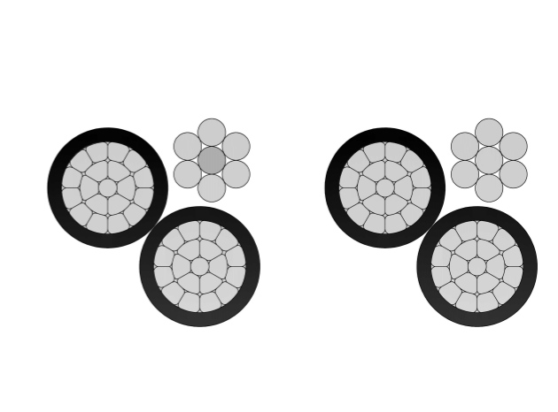
Construction
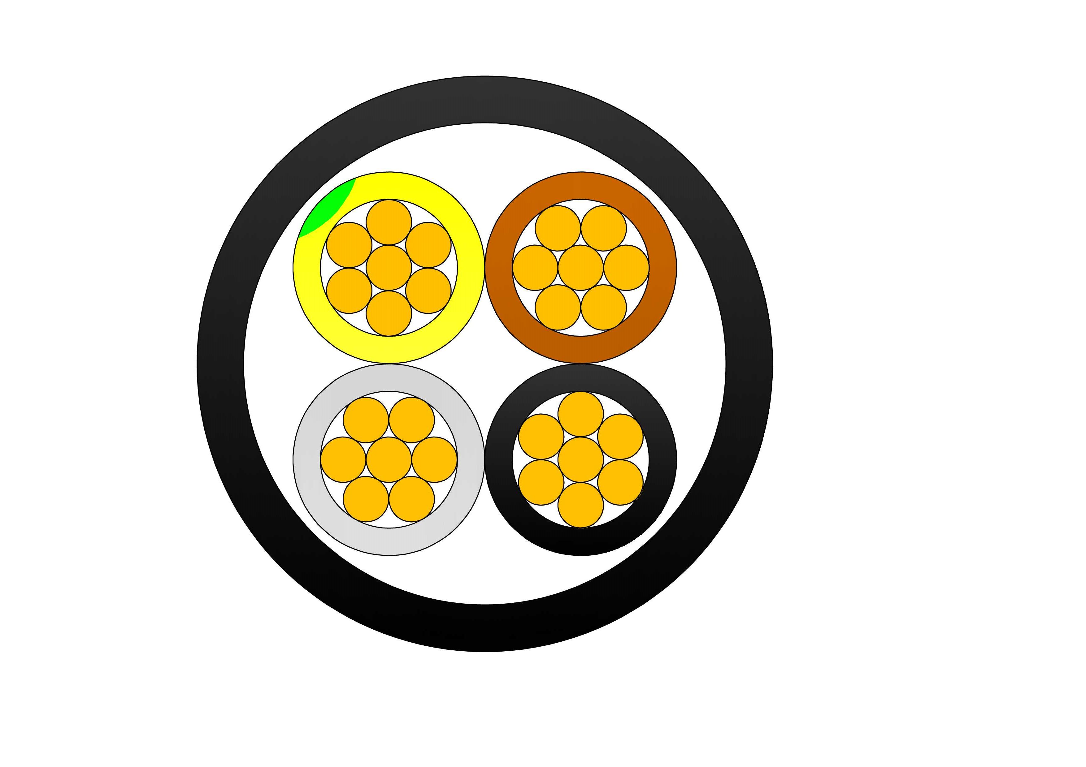
Steel Wire Armoured Cable Construction
Product Features
Galvanized steel wire armour protection
Excellent tensile and impact resistance
Suitable for direct burial installation
Premium XLPE insulation system
Durable PVC outer sheath
High mechanical strength
Moisture and corrosion resistance Long service life
Excellent tensile and impact resistance
Suitable for direct burial installation
Premium XLPE insulation system
Durable PVC outer sheath
High mechanical strength
Moisture and corrosion resistance Long service life
Conductor
Stranded copper (Class 2)
Insulation
XLPE
Inner Sheath
PVC
Outer Sheath
PVC (ST2)
Armour
Galvanized steel wire (SWA)
Standard
IEC 60502-1
Technical Specifications
Steel Wire Armoured Cable (SWA Cable) for Power Distribution Systems
Steel Wire Armoured Cable (SWA Cable) Data Sheet
|
0.6/1kV-2 core copper conductor XLPE insulated steel wire armored PVC sheathed power cable |
||||||||
|
Nominal cross sectional area |
Insulation thickness |
Steel Wire diameter |
Sheath thickness |
Approximate outer diameter |
Approx. weight |
Max.D.C resistance of conductor(20℃) |
Current carrying capacity |
|
|
mm2 |
mm |
mm |
mm |
mm |
kg/km |
Ω/km |
In Air(A) |
In Ground(A) |
|
2X2.5 |
0.7 |
0.8 |
1.8 |
14.8 |
364 |
7.41 |
23 |
32 |
|
2X4 |
0.7 |
0.8 |
1.8 |
15.7 |
425 |
4.61 |
30 |
41 |
|
2X6 |
0.7 |
1.25 |
1.8 |
17.6 |
646 |
3.08 |
39 |
53 |
|
2X10 |
0.7 |
1.25 |
1.8 |
20.1 |
802 |
1.83 |
53 |
70 |
|
2X16 |
0.7 |
1.25 |
1.8 |
22.3 |
1008 |
1.15 |
68 |
91 |
|
2X25 |
0.9 |
1.6 |
1.8 |
26.3 |
1470 |
0.727 |
91 |
116 |
|
2X35 |
0.9 |
1.6 |
1.8 |
27.6 |
1712 |
0.524 |
112 |
140 |
|
2X50 |
1 |
1.6 |
1.9 |
30.8 |
2123 |
0.387 |
137 |
168 |
|
2X70 |
1.1 |
2 |
2 |
35.4 |
2974 |
0.268 |
172 |
203 |
|
2X95 |
1.1 |
2 |
2.1 |
39.5 |
3737 |
0.193 |
214 |
249 |
|
2X120 |
1.2 |
2 |
2.3 |
42.9 |
4453 |
0.153 |
249 |
284 |
|
2X150 |
1.4 |
2.5 |
2.4 |
48 |
5744 |
0.124 |
284 |
315 |
|
2X185 |
1.6 |
2.5 |
2.6 |
52.7 |
6811 |
0.0991 |
326 |
357 |
|
|
|
|
|
|
|
|
|
|
|
0.6/1kV-3 core copper conductor XLPE insulated steel wire armored PVC sheathed power cable |
||||||||
|
Nominal cross sectional area |
Insulation thickness |
Steel Wire diameter |
Sheath thickness |
Approximate outer diameter |
Approx. weight |
Max.D.C resistance of conductor(20℃) |
Current carrying capacity |
|
|
mm2 |
mm |
mm |
mm |
mm |
kg/km |
Ω/km |
In Air(A) |
In Ground(A) |
|
3X2.5 |
0.7 |
0.8 |
1.8 |
15.3 |
405 |
7.41 |
20 |
27 |
|
3X4 |
0.7 |
0.8 |
1.8 |
16.2 |
481 |
4.61 |
26 |
36 |
|
3X6 |
0.7 |
1.25 |
1.8 |
18.3 |
696 |
3.08 |
33 |
45 |
|
3X10 |
0.7 |
1.25 |
1.8 |
20.9 |
930 |
1.83 |
46 |
60 |
|
3X16 |
0.7 |
1.25 |
1.8 |
23.3 |
1191 |
1.15 |
59 |
77 |
|
3X25 |
0.9 |
1.6 |
1.8 |
27.6 |
1745 |
0.727 |
77 |
98 |
|
3X35 |
0.9 |
1.6 |
1.8 |
29 |
2100 |
0.524 |
95 |
119 |
|
3X50 |
1 |
1.6 |
1.9 |
32.5 |
2628 |
0.387 |
119 |
144 |
|
3X70 |
1.1 |
2 |
2.1 |
37.9 |
3728 |
0.268 |
151 |
175 |
|
3X95 |
1.1 |
2 |
2.2 |
41.8 |
4692 |
0.193 |
186 |
210 |
|
3X120 |
1.2 |
2 |
2.3 |
45.5 |
5645 |
0.153 |
217 |
242 |
|
3X150 |
1.4 |
2.5 |
2.5 |
51.3 |
7350 |
0.124 |
245 |
270 |
|
3X185 |
1.6 |
2.5 |
2.7 |
55.9 |
8698 |
0.0991 |
284 |
305 |
|
3X240 |
1.7 |
2.5 |
2.9 |
62.1 |
10837 |
0.0754 |
336 |
350 |
|
3X300 |
1.8 |
2.5 |
3 |
67.4 |
12990 |
0.0601 |
389 |
396 |
|
|
|
|
|
|
|
|
|
|
|
0.6/1kV-4 core copper conductor XLPE insulated steel wire armored PVC sheathed power cable |
||||||||
|
Nominal cross sectional area |
Insulation thickness |
Steel Wire diameter |
Sheath thickness |
Approximate outer diameter |
Approx. weight |
Max.D.C resistance of conductor(20℃) |
Current carrying capacity |
|
|
mm2 |
mm |
mm |
mm |
mm |
kg/km |
Ω/km |
In Air(A) |
In Ground(A) |
|
4X2.5 |
0.7 |
0.8 |
1.8 |
16.1 |
472 |
7.41 |
20 |
27 |
|
4X4 |
0.7 |
1.25 |
1.8 |
18.1 |
677 |
4.61 |
26 |
36 |
|
4X6 |
0.7 |
1.25 |
1.8 |
19.3 |
804 |
3.08 |
33 |
45 |
|
4X10 |
0.7 |
1.25 |
1.8 |
22.3 |
1088 |
1.83 |
46 |
60 |
|
4X16 |
0.7 |
1.6 |
1.8 |
25.7 |
1571 |
1.15 |
59 |
77 |
|
4X25 |
0.9 |
1.6 |
1.8 |
29.7 |
2085 |
0.727 |
77 |
98 |
|
4X35 |
0.9 |
1.6 |
1.9 |
31.4 |
2543 |
0.524 |
95 |
119 |
|
4X50 |
1 |
1.6 |
2 |
35.3 |
3214 |
0.387 |
119 |
144 |
|
4X70 |
1.1 |
2 |
2.2 |
41.2 |
4571 |
0.268 |
151 |
175 |
|
4X95 |
1.1 |
2 |
2.3 |
45.6 |
5782 |
0.193 |
186 |
210 |
|
4X120 |
1.2 |
2.5 |
2.5 |
51.2 |
7557 |
0.153 |
217 |
242 |
|
4X150 |
1.4 |
2.5 |
2.7 |
56.1 |
9080 |
0.124 |
245 |
270 |
|
4X185 |
1.6 |
2.5 |
2.8 |
61.3 |
10822 |
0.0991 |
284 |
305 |
|
4X240 |
1.7 |
2.5 |
3.1 |
68.1 |
13566 |
0.0754 |
336 |
350 |
|
4X300 |
1.8 |
2.5 |
3.2 |
74.1 |
16356 |
0.0601 |
389 |
396 |
|
|
|
|
|
|
|
|
|
|
|
0.6/1kV-5 core copper conductor XLPE insulated steel wire armored PVC sheathed power cable |
||||||||
|
Nominal cross sectional area |
Insulation thickness |
Steel Wire diameter |
Sheath thickness |
Approximate outer diameter |
Approx. weight |
Max.D.C resistance of conductor(20℃) |
Current carrying capacity |
|
|
mm2 |
mm |
mm |
mm |
mm |
kg/km |
Ω/km |
In Air(A) |
In Ground(A) |
|
5X2.5 |
0.7 |
1.25 |
1.8 |
17.9 |
645 |
7.41 |
20 |
27 |
|
5X4 |
0.7 |
1.25 |
1.8 |
19.1 |
770 |
4.61 |
26 |
36 |
|
5X6 |
0.7 |
1.25 |
1.8 |
20.5 |
925 |
3.08 |
33 |
45 |
|
5X10 |
0.7 |
1.6 |
1.8 |
24.6 |
1417 |
1.83 |
46 |
60 |
|
5X16 |
0.7 |
1.6 |
1.8 |
27.6 |
1812 |
1.15 |
59 |
77 |
|
5X25 |
0.9 |
1.6 |
1.9 |
32.2 |
2460 |
0.727 |
77 |
98 |
|
5X35 |
0.9 |
1.6 |
2 |
34.1 |
3019 |
0.524 |
95 |
119 |
|
5X50 |
1 |
2 |
2.2 |
39.7 |
4166 |
0.387 |
119 |
144 |
|
5X70 |
1.1 |
2 |
2.3 |
44.9 |
5443 |
0.268 |
151 |
175 |
|
5X95 |
1.1 |
2.5 |
2.5 |
51.3 |
7485 |
0.193 |
186 |
210 |
|
5X120 |
1.2 |
2.5 |
2.7 |
55.9 |
9026 |
0.153 |
217 |
242 |
|
5X150 |
1.4 |
2.5 |
2.8 |
61.4 |
10912 |
0.124 |
245 |
270 |
|
5X185 |
1.6 |
2.5 |
3 |
67.6 |
13119 |
0.0991 |
284 |
305 |
|
5X240 |
1.7 |
2.5 |
3.3 |
74.8 |
16427 |
0.0754 |
336 |
350 |
|
5X300 |
1.8 |
3.15 |
3.5 |
83.2 |
20915 |
0.0601 |
389 |
396 |
|
|
|
|
|
|
|
|
|
|
|
0.6/1kV-3+1 core copper conductor XLPE insulated steel wire armored PVC sheathed power cable |
||||||||
|
Nominal cross sectional area |
Insulation thickness |
Steel Wire diameter |
Sheath thickness |
Approximate outer diameter |
Approx. weight |
Max.D.C resistance of conductor(20℃) |
Current carrying capacity |
|
|
mm2 |
mm |
mm |
mm |
mm |
kg/km |
Ω/km |
In Air(A) |
In Ground(A) |
|
3X4+1X2.5 |
0.7/0.7 |
1.25 |
1.8 |
17.8 |
873 |
4.61/7.41 |
26 |
36 |
|
3X6+1X4 |
0.7/0.7 |
1.25 |
1.8 |
19.1 |
764 |
3.08/4.61 |
33 |
45 |
|
3X10+1X6 |
0.7/0.7 |
1.25 |
1.8 |
21.6 |
1002 |
1.83/3.08 |
46 |
60 |
|
3X16+1X10 |
0.7/0.7 |
1.6 |
1.8 |
25.1 |
1475 |
1.15/1.83 |
59 |
77 |
|
3X25+1X16 |
0.9/0.7 |
1.6 |
1.8 |
28.7 |
2101 |
0.727/1.15 |
77 |
98 |
|
3X35+1X16 |
0.9/0.7 |
1.6 |
1.8 |
30 |
2300 |
0.524/1.15 |
95 |
119 |
|
3X50+1X25 |
1/0.9 |
1.6 |
2 |
34.1 |
2945 |
0.387/0.727 |
119 |
144 |
|
3X70+1X35 |
1.1/0.9 |
2 |
2.1 |
39.2 |
4131 |
0.268/0.524 |
151 |
175 |
|
3X95+1X50 |
1.1/1.0 |
2 |
2.3 |
43.2 |
5199 |
0.193/0.387 |
186 |
210 |
|
3X120+1X70 |
1.2/1.1 |
2.5 |
2.4 |
48.8 |
6827 |
0.153/0.268 |
217 |
242 |
|
3X150+1X70 |
1.4/1.1 |
2.5 |
2.6 |
52.9 |
7915 |
0.124/0.268 |
245 |
270 |
|
3X185+1X95 |
1.6/1.1 |
2.5 |
2.7 |
57.8 |
9655 |
0.0991/0.193 |
284 |
305 |
|
3X240+1X120 |
1.7/1.2 |
2.5 |
2.9 |
64.1 |
11988 |
0.0754/0.153 |
336 |
350 |
|
3X300+1X150 |
1.8/1.4 |
2.5 |
3.1 |
69.8 |
14475 |
0.0601/0.124 |
389 |
396 |
|
|
|
|
|
|
|
|
|
|
|
0.6/1kV-4+1 core copper conductor XLPE insulated steel wire armored PVC sheathed power cable |
||||||||
|
Nominal cross sectional area |
Insulation thickness |
Steel Wire diameter |
Sheath thickness |
Approximate outer diameter |
Approx. weight |
Max.D.C resistance of conductor(20℃) |
Current carrying capacity |
|
|
mm2 |
mm |
mm |
mm |
mm |
kg/km |
Ω/km |
In Air(A) |
In Ground(A) |
|
4X4+1X2.5 |
0.7/0.7 |
1.25 |
1.8 |
18.9 |
731 |
4.61/7.41 |
26 |
36 |
|
4X6+1X4 |
0.7/0.7 |
1.25 |
1.8 |
20.3 |
875 |
3.08/4.61 |
33 |
45 |
|
4X10+1X6 |
0.7/0.7 |
1.6 |
1.8 |
23.9 |
1295 |
1.83/3.08 |
46 |
60 |
|
4X16+1X10 |
0.7/0.7 |
1.6 |
1.8 |
27 |
1712 |
1.15/1.83 |
59 |
77 |
|
4X25+1X16 |
0.9/0.7 |
1.6 |
1.9 |
31.2 |
2322 |
0.727/1.15 |
77 |
98 |
|
4X35+1X16 |
0.9/0.7 |
1.6 |
1.9 |
32.8 |
2759 |
0.524/1.15 |
95 |
119 |
|
4X50+1X25 |
1/0.9 |
2 |
2.1 |
38.5 |
3860 |
0.387/0.727 |
119 |
144 |
|
4X70+1X35 |
1.1/0.9 |
2 |
2.3 |
43 |
5010 |
0.268/0.524 |
151 |
175 |
|
4X95+1X50 |
1.1/1.0 |
2.5 |
2.4 |
48.9 |
6850 |
0.193/0.387 |
186 |
210 |
|
4X120+1X70 |
1.2/1.1 |
2.5 |
2.6 |
54 |
8395 |
0.153/0.268 |
217 |
242 |
|
4X150+1X70 |
1.4/1.1 |
2.5 |
2.7 |
58.4 |
9745 |
0.124/0.268 |
245 |
270 |
|
4X185+1X95 |
1.6/1.1 |
2.5 |
2.9 |
64.4 |
11948 |
0.0991/0.193 |
284 |
305 |
|
4X240+1X120 |
1.7/1.2 |
2.5 |
3.1 |
71.1 |
14832 |
0.0754/0.153 |
336 |
350 |
|
4X300+1X150 |
1.8/1.4 |
3.15 |
3.4 |
78.9 |
18826 |
0.0601/0.124 |
389 |
396 |
|
|
|
|
|
|
|
|
|
|
|
0.6/1kV-3+2 core copper conductor XLPE insulated steel wire armored PVC sheathed power cable |
||||||||
|
Nominal cross sectional area |
Insulation thickness |
Steel Wire diameter |
Sheath thickness |
Approximate outer diameter |
Approx. weight |
Max.D.C resistance of conductor(20℃) |
Current carrying capacity |
|
|
mm2 |
mm |
mm |
mm |
mm |
kg/km |
Ω/km |
In Air(A) |
In Ground(A) |
|
3X4+2X2.5 |
0.7/0.7 |
1.25 |
1.8 |
18.6 |
705 |
4.61/7.41 |
26 |
36 |
|
3X6+2X4 |
0.7/0.7 |
1.25 |
1.8 |
20 |
845 |
3.08/4.61 |
33 |
45 |
|
3X10+2X6 |
0.7/0.7 |
1.25 |
1.8 |
22.5 |
1109 |
1.83/3.08 |
46 |
60 |
|
3X16+2X10 |
0.7/0.7 |
1.6 |
1.8 |
26.5 |
1630 |
1.15/1.83 |
59 |
77 |
|
3X25+2X16 |
0.9/0.7 |
1.6 |
1.8 |
30.2 |
2185 |
0.727/1.15 |
77 |
98 |
|
3X35+2X16 |
0.9/0.7 |
1.6 |
1.9 |
31.3 |
2505 |
0.524/1.15 |
95 |
119 |
|
3X50+2X25 |
1/0.9 |
2 |
2.1 |
37 |
3531 |
0.387/0.727 |
119 |
144 |
|
3X70+2X35 |
1.1/0.9 |
2 |
2.2 |
41.1 |
4572 |
0.268/0.524 |
151 |
175 |
|
3X95+2X50 |
1.1/1.0 |
2 |
2.4 |
45.8 |
5841 |
0.193/0.387 |
186 |
210 |
|
3X120+2X70 |
1.2/1.1 |
2.5 |
2.6 |
52.1 |
7765 |
0.153/0.268 |
217 |
242 |
|
3X150+2X70 |
1.4/1.1 |
2.5 |
2.7 |
55.4 |
8758 |
0.124/0.268 |
245 |
270 |
|
3X185+2X95 |
1.6/1.1 |
2.5 |
2.8 |
60.8 |
10777 |
0.0991/0.193 |
284 |
305 |
|
3X240+2X120 |
1.7/1.2 |
2.5 |
3 |
67.4 |
13385 |
0.0754/0.153 |
336 |
350 |
|
3X300+2X150 |
1.8/1.4 |
2.5 |
3.2 |
73.6 |
16100 |
0.0601/0.124 |
389 |
396 |
Quality Control
Steel Wire Armoured Cable (SWA Cable) for Power Distribution Systems
Raw Material Test
Raw material testing for the Steel Wire Armoured Cable SWA 0.6/1kV CU/XLPE/SWA/PVC ensures full compliance with IEC 60502-1. Copper rods are tested for purity, conductivity (>99% IACS), and elongation. XLPE insulation compound is rigorously evaluated for density, melt flow index, antioxidant levels, and crosslinking potential using OIT and DSC analysis. Galvanized steel wires undergo zinc coating mass, tensile strength, and corrosion resistance tests. PVC sheath material is checked for thermal stability and hardness. The step-by-step process includes incoming batch verification, random sampling, chemical composition analysis via spectrometry, mechanical property testing before and after aging, armour corrosion pre-checks, and final material approval decision. Only qualified materials are released, guaranteeing the Steel Wire Armoured Cable SWA 0.6/1kV CU/XLPE/SWA/PVC achieves excellent conductivity, insulation integrity, strong armour protection, and long-term durability.
Process inspection
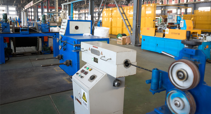
During manufacturing of the Steel Wire Armoured Cable SWA 0.6/1kV CU/XLPE/SWA/PVC, process inspection maintains strict quality control. Copper conductor stranding is monitored for compactness. XLPE insulation extrusion controls thickness and concentricity with online systems. PVC inner sheath prepares a smooth surface for armouring. Galvanized steel wire armouring verifies helical winding, tension balance, and coverage. Final PVC outer sheath extrusion includes real-time spark testing. Key steps include material pre-drying confirmation, extrusion and armouring parameter logging, intermediate hot set tests for crosslinking degree, armour gap and overlap checks, defect detection with immediate correction, and controlled cooling. This multi-stage oversight guarantees the Steel Wire Armoured Cable SWA 0.6/1kV CU/XLPE/SWA/PVC achieves void-free insulation, strong armour adhesion, precise construction, and full IEC 60502-1 compliance throughout production.
Finished Product
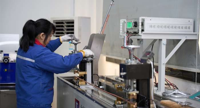
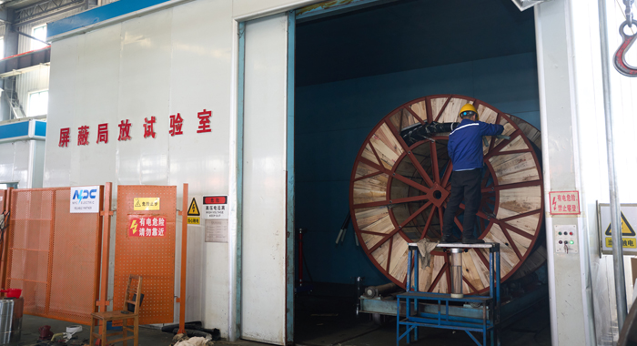
The finished Steel Wire Armoured Cable SWA 0.6/1kV CU/XLPE/SWA/PVC undergoes comprehensive testing. Routine tests include conductor resistance, AC voltage withstand (3.5kV), insulation and sheath thickness verification, and armour continuity checks. Mechanical tests cover crushing resistance, impact endurance, and tensile strength. Flame retardancy per IEC 60332-1 is verified. The process steps include sample preparation, gradual voltage ramp-up and hold period, mechanical load application (crushing and impact), environmental conditioning, post-test electrical and mechanical re-measurement, and detailed visual inspection. Additional checks cover shrinkage, heat shock, and marking durability. Only cables passing all criteria are approved, confirming the Steel Wire Armoured Cable SWA 0.6/1kV CU/XLPE/SWA/PVC’s superior mechanical protection, electrical safety, and suitability for demanding installations.
Application
Steel Wire Armoured Cable SWA 0.6/1kV is ideal for direct burial, underground ducts, and exposed installations in industrial plants, substations, commercial buildings, and infrastructure projects requiring strong mechanical protection and reliable low voltage power transmission.


Technical Advantages
● 30+ years of manufacturing experience
● ISO and UL certified production
● Customized cable and transformer solutions


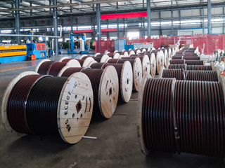
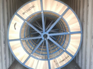
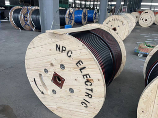
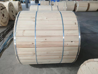
Product Packaging
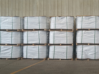
Wires and Cables packaging (1)
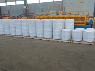
Wires and Cables packaging (2)
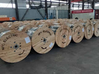
Wires and Cables packaging (3)
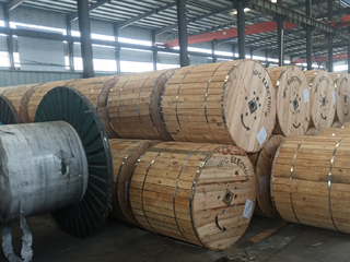
Wires and Cables packaging (4)
Wires and Cables packaging (5)
Wires and Cables packaging (6)
Wires and Cables packaging (7)
Wires and Cables packaging (8)
Related Products
2 Clam Aluminum Conductor Triplex Overhead Service Drop Cable
2-2-2 Clam Aluminum Conductor Triplex Overhead Service Drop Cable provides high-performance overhead power transmission for utility-to-consumer connections. Constructed with compressed or concentric 1350-H19 aluminum phase conductors (#2 AWG), durable black XLPE insulation for enhanced thermal and environmental protection, and a bare neutral messenger (#2 AWG ACSR or AAC), it delivers efficient conductivity, corrosion resistance, and structural support. Suitable for 600V phase-to-phase applications with conductor temperatures up to 90°C, offering ≈150A ampacity. Meets or exceeds ASTM B-230/B-231/B-232/B-399 and ICEA S-76-474 requirements. Its lightweight design and flexibility make installation efficient, while rugged construction ensures long service life in demanding outdoor exposure to weather, abrasion, and mechanical stress.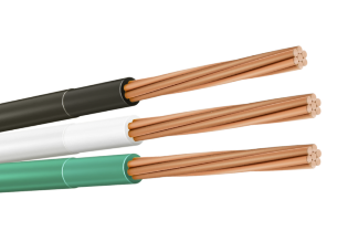
THHN AND THWN
Electrical wire THHN THWN is used in new construction projects or rewiring tasks in 600-volt systems. Versatile and usable in both wet and dry locations, THHN/THWN-2 is an excellent choice for a wide range of electrical installations. THHN/THWN-2 conductors can withstand temperatures up to 90°C in dry environments and up to 75°C in the presence of oil or coolant. Its outer nylon jacket is smooth and fine, ensuring easy installation by reducing friction during pulling. This feature is especially useful for long or challenging runs.
1/0 Leda Aluminum Conductor Triplex Overhead Service Drop Cable
The 1/0 Leda Triplex Service Drop Cable is a durable overhead cable for secondary power distribution to residential service entrances. Featuring two 1/0 AWG aluminum phase conductors and one neutral messenger (7-strand) insulated with XLPE or PE and assembled in triplex configuration, it provides excellent mechanical strength and weather resistance. Compliant with ASTM B-230, B-231, ICEA S-76-474, and ANSI/ICEA standards, this cable supports 600V applications with high UV, moisture, and abrasion protection. The self-supporting messenger reduces sag and simplifies installation over medium spans. The 1/0 Leda Triplex Service Drop Cable ensures low power losses, high current capacity, and long service life in harsh outdoor conditions. Lightweight and flexible, it is widely used for two-phase service drops with neutral in urban, suburban, and rural areas requiring safe, cost-effective aerial connections from utility poles to homes.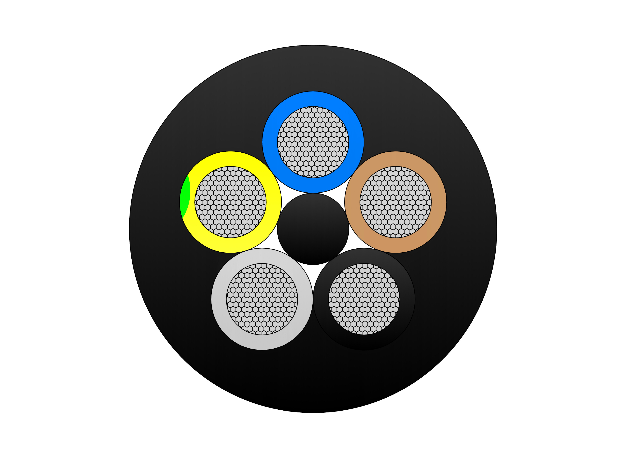
(N)TSCGECEWOU - 3.6/6kV, 6/10kV, 8.7/15kV and 12/20kV Submersible Cable
The (N)TSCGECEWOU - 3.6/6kV, 6/10kV, 8.7/15kV, and 12/20kV Submersible Cable is a flexible, heavy-duty medium-voltage cable designed for submersible applications in mining, tunneling, and industrial water environments. It features class 5 finely stranded tinned copper conductors for flexibility and corrosion resistance, semi-conductive conductor and insulation screens, EPR (ethylene propylene rubber) insulation for superior dielectric strength and 90°C continuous rating, copper braid screen for EMI protection and grounding, control/monitoring conductors, and a watertight, abrasion-resistant rubber outer sheath (e.g., 5GM5 type) that prevents water ingress up to high pressures (e.g., 50 bar). Compliant with DIN VDE 0250 and relevant IEC standards, it offers high mechanical strength, longitudinal water blocking, and resistance to oils, chemicals, and flames. Suitable for submersible pumps, dredgers, and underwater equipment, the (N)TSCGECEWOU Submersible ensures reliable power transmission in submerged conditions with minimal maintenance.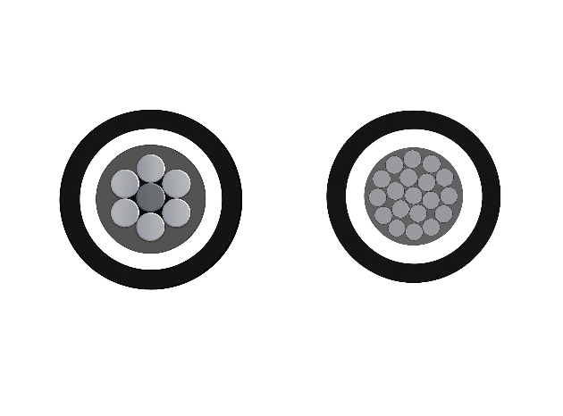
25kV 3-Layer AAAC/ACSR/AAC Tree Wire - Triple Layer Covered MV Conductor
The 3-Layer 25kV AAAC/ACSR/AAC Tree Wire is a specialized covered medium-voltage overhead conductor developed for distribution lines in areas with dense vegetation. It uses concentrically stranded AAAC, ACSR, or AAC conductors protected by a triple-layer system of track-resistant HDPE or XLPE. The multi-layer covering delivers exceptional tracking resistance, abrasion protection, and weatherability while greatly reducing the risk of electrical faults from tree limb contact and helping minimize wildfire ignition potential. This advanced design allows closer spacing to vegetation and lowers vegetation management costs. Suitable for conventional overhead or spacer cable systems, the 3-Layer 25kV AAAC/ACSR/AAC Tree Wire offers a cost-effective solution for improving line reliability. It complies with ICEA and ASTM standards and undergoes extensive quality testing to ensure long-term performance and safety.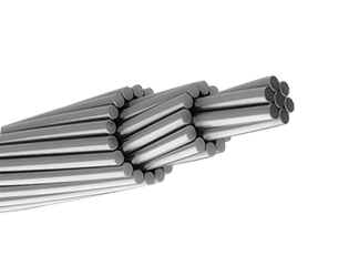
336.4 MCM MERLIN ACSR Conductor Cable
The ACSR CAA 336.4 KCM 18/1F MERLIN is a robust and efficient aluminium conductor steel reinforced cable, designed for high-performance in overhead power transmission and distribution lines. This conductor consists of 18 strands of hard-drawn 1350-H19 aluminium helically stranded around a single galvanized steel core wire, delivering an ideal combination of electrical conductivity and mechanical strength. Compliant with ASTM B232, this ACSR configuration is widely adopted in South American and international power systems. The steel core, galvanized to Class A or B, offers protection against corrosion, ensuring long service life in harsh environmental conditions. Meanwhile, the aluminium strands provide excellent current-carrying capacity and conductivity. The MERLIN design is particularly suitable for medium-voltage transmission lines and long-span installations where mechanical tension and conductor sag need to be controlled without compromising electrical performance.FAQ From Customers
-
What are the advantages of power cables and overhead lines?(1) Reliable operation, because it is installed in a hidden place such as underground, it is less damaged by external forces, has less chance of failure, and the power supply is safe, and it will not cause harm to people; (2) The maintenance workload is small and frequent inspections are not required; (3) No need to erect towers; (4) Help improve power factor.
-
Which aspects should be considered when choosing the cross section of a power cable?(1) The long-term allowable working current of the cable; (2) Thermal stability once short circuited; (3) The voltage drop on the line cannot exceed the allowable working range.
-
What are the measures for cable fire prevention?(1) Use flame-retardant cables; (2) Use fireproof cable tray; (3) Use fireproof paint; (4) Fire partition walls and fire baffles are installed at cable tunnels, mezzanine exits, etc.; (5) Overhead cables should avoid oil pipelines and explosion-proof doors, otherwise local pipes or heat insulation and fire prevention measures should be taken.
-
What should be paid attention to during the transportation and handling of cables?(1) During transportation, loading and unloading, cables and cable reels should not be damaged. It is strictly forbidden to push the cable reels directly from the vehicle. Generally, cables should not be transported and stored flat. (2) Before transporting or rolling the cable reel, ensure that the cable reel is firm, the cable is wound tightly, the oil pipe between the oil-filled cable and the pressure oil tank should be fixed without damage, the pressure oil tank should be firm, and the pressure indication should meet the requirements.
-
What inspections should be carried out for the acceptance of cable lines?(1) The cable specifications should meet the regulations, the arrangement should be neat, no damage, and the signs should be complete, correct and clear; (2) The fixed bending radius of the cable, the related distance and the wiring of the metal sheath of the single-core power cable should meet the requirements; (3) The cable terminal and the middle head should not leak oil, and the installation should be firm. The oil pressure of the oil-filled cable and the meter setting should meet the requirements; (4) Good grounding; (5) The color of the cable terminal is correct, and the metal parts such as the bracket are completely painted; (6) There should be no debris in the cable trench, tunnel, and bridge, and the cover should be complete.
Welcome your inquiry
Honesty, Integrity, Frugality, Activeness and Passion