



High Voltage Switchgear
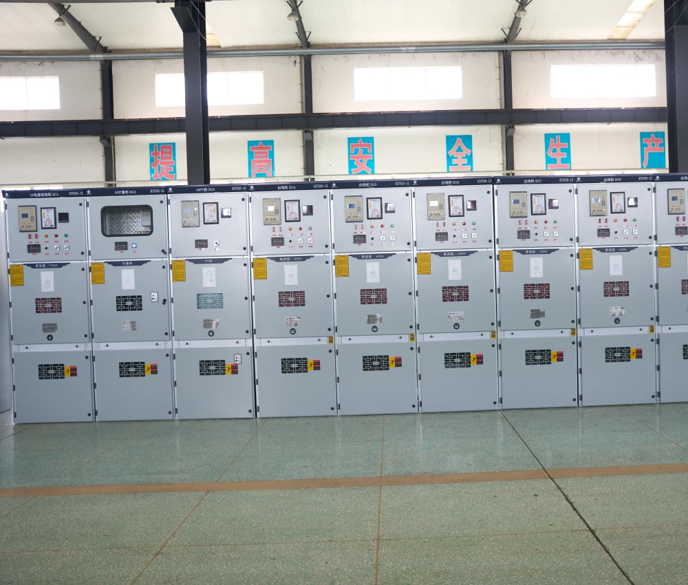
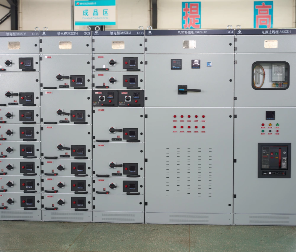
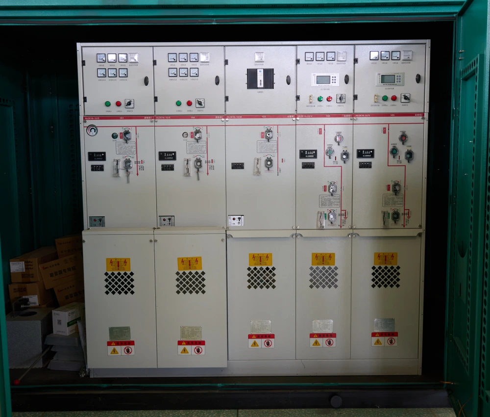
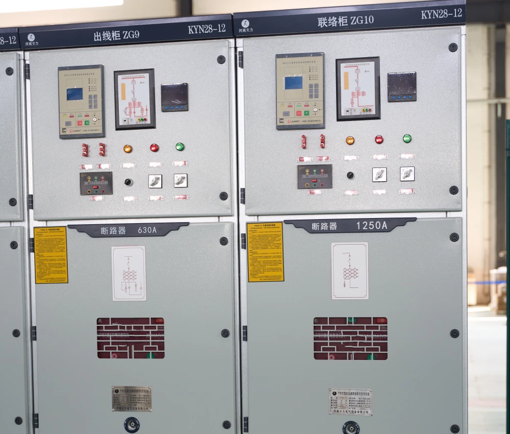
NPC Electric high voltage switchgear delivers exceptional reliability and safety for modern electrical networks. Built with cutting-edge insulation technology and intelligent monitoring systems, this HV switchgear ensures seamless power distribution while protecting critical infrastructure from faults and overloads. Ideal for utilities, industrial plants, and renewable energy projects, it combines compact design with robust construction to minimize downtime and maximize operational efficiency in demanding environments.
- Primary Voltage Ratings 72.5kV - 252kV
- Type Switchgear
- Standards IEC 62271, GB/T 11022, ANSI/IEEE
- Application power distribution, renewable energy collection stations
- Power Rating --
- Certificate UL, CESI, IEEE
- Cooling Method ONAN / ONAF
Technical Specifications
Customization Optional
Packing and Shipping
Manufacturer Test
Routine Testing
Application
Technical Specifications
High Voltage Switchgear
High Voltage Switchgear Data Sheet
| Parameter Category | Technical Parameter | Specification Range / Typical Value | Unit | Remarks / Standard |
| Rated Voltage | Ur | 72.5 / 126 / 145 / 170 / 252 | kV | IEC 62271-1 |
| Rated Current | Ir | 630 / 1250 / 1600 / 2000 / 2500 / 3150 / 4000 | A | Busbar & Circuit Breaker |
| Short-time Withstand Current | Ik | 25 / 31.5 / 40 / 50 | kA | 3s or 4s duration |
| Peak Withstand Current | Ip | 63 / 80 / 100 / 125 / 160 | kA | Peak value |
| Power Frequency Withstand Voltage | Ud | 140 / 230 / 275 / 325 / 460 | kV | 1 minute, dry test |
| Lightning Impulse Withstand Voltage | Up | 325 / 550 / 650 / 750 / 950 / 1050 | kV | 1.2/50μs |
| Rated Short-Circuit Breaking Current | Isc | 25 / 31.5 / 40 / 50 | kA | Circuit Breaker |
| Rated Short-Circuit Making Current | Im | 63 / 80 / 100 / 125 | kA | Peak |
| Operating Sequence | - | O-0.3s-CO-3min-CO | - | Standard for Circuit Breaker |
| Mechanical Endurance | M | 10,000 operations (Circuit Breaker) 5,000 operations (Disconnector) | Operations | IEC Standard |
| Electrical Endurance | E | 2,000 – 5,000 operations | Operations | At rated current |
| Insulation Medium | - | SF6 Gas / Dry Air / Solid Dielectric (AIS/GIS) | - | Optional |
| Protection Degree | IP Code | IP54 (Indoor) / IP65 (Outdoor) | - | Enclosure Protection |
| Operating Mechanism | - | Spring Stored Energy / Hydraulic / Motorized | - | Customizable |
| Creepage Distance | - | ≥31mm/kV (Up to 45mm/kV for heavy pollution) | mm/kV | According to pollution level |
| Seismic Withstand Capability | - | 0.3g – 0.5g | - | Can be enhanced |
| Ambient Temperature | - | -40°C to +55°C (Special: -50°C) | °C | Outdoor Type |
| Relative Humidity | - | Up to 95% (daily average) | % | No condensation |
| Installation Type | - | Indoor / Outdoor / Box-type / Mobile | - | Highly customizable |
| Smart Monitoring | - | IEC 61850, Partial Discharge Monitoring, SF6 Gas Density, Temperature & Humidity Monitoring | - | Optional |
Customization Optional
High Voltage Switchgear
NPC Electric high voltage switchgear offers extensive customization to meet diverse project requirements across various voltage levels and environmental conditions. Clients can select from multiple configurations including Gas Insulated Switchgear (GIS) or Air Insulated Switchgear (AIS) layouts, single busbar, double busbar, or ring main unit designs. We provide tailored current ratings, specialized arc-resistant enclosures, and integration options with smart monitoring systems such as partial discharge sensors, temperature monitoring, and remote SCADA connectivity. Material choices range from high-grade stainless steel for corrosive environments to lightweight aluminum alloys for weight-sensitive installations. Additional features like motorized spring mechanisms, advanced interlocking systems, and custom color schemes ensure full compatibility with existing substation infrastructure.
Furthermore, we accommodate specific functional needs through modular compartment designs that allow easy expansion or retrofitting. Customers may request enhanced seismic resistance for earthquake-prone areas, extreme temperature adaptations for desert or polar climates, and specialized cable entry configurations. Our engineering team works closely with clients to incorporate unique protection relays, current transformers, voltage transformers, and surge arresters tailored to exact system parameters. Whether for renewable energy integration requiring fast fault isolation or heavy industrial applications demanding high short-circuit ratings, we deliver fully customized high voltage switchgear solutions that optimize performance, safety, and lifecycle costs while maintaining full compliance with international standards such as IEC, ANSI, and GB.
Packing and Shipping
High Voltage Switchgear
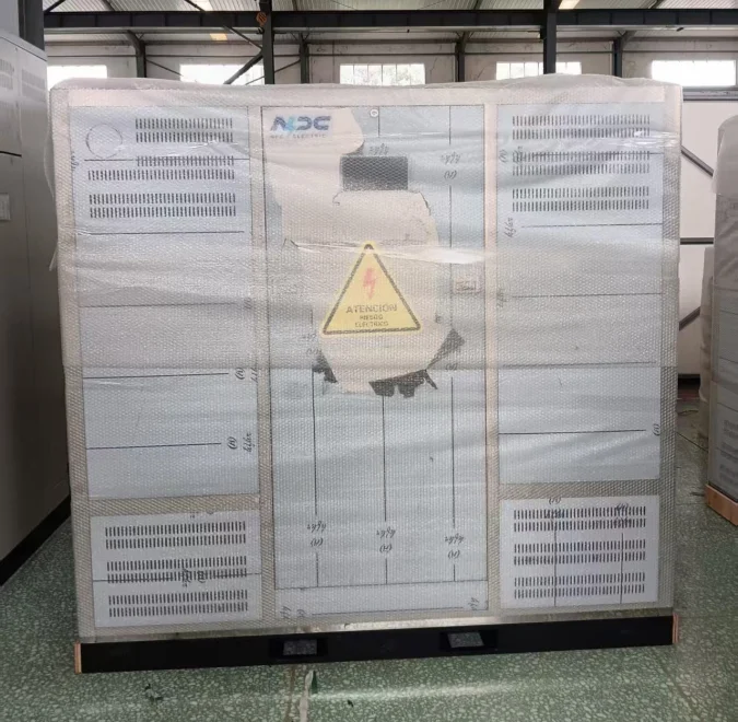
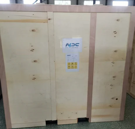
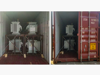
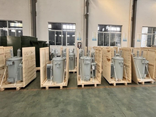
We ensure the highest standards in packing and shipping for all high voltage switchgear units to guarantee safe arrival at project sites worldwide. Each HV switchgear module undergoes meticulous protective packaging using heavy-duty wooden crates reinforced with steel frames and shock-absorbing materials. Internal components are secured with custom foam inserts and anti-vibration mounts to prevent movement during long-distance transport. Critical parts such as circuit breakers, busbars, and instrument transformers receive individual moisture-proof wrapping with desiccant packs, while sensitive electronic monitoring devices are packed in anti-static bags. Every package includes clear labeling with handling instructions, serial numbers, and QR codes for easy tracking.
Our shipping process incorporates comprehensive logistics planning tailored to customer destinations. For inland deliveries, we utilize specialized flatbed trucks equipped with hydraulic lifting systems and GPS monitoring. International shipments are handled via sea freight in 40-foot high-cube containers or air freight for urgent requirements, with full insurance coverage against transit damage. We coordinate with certified freight forwarders experienced in handling high voltage electrical equipment to comply with all export regulations, including proper documentation for hazardous materials like SF6 gas if applicable. Pre-shipment inspections and sealing of containers ensure integrity throughout the journey.
Upon arrival, we provide detailed unpacking guidance and optional on-site supervision services to support installation teams. All packing materials are designed for sustainability, with options for returnable crates to reduce environmental impact. Our global network of warehouses allows for strategic stocking and faster delivery times to key markets in Asia, Europe, Middle East, and Africa. Temperature-controlled shipping is available for sensitive components in extreme climates. We maintain complete traceability from factory to site, offering real-time updates to customers regarding shipment status, customs clearance, and delivery schedules. This meticulous approach minimizes risks of transit damage and ensures your high voltage switchgear arrives in perfect condition ready for immediate deployment.
Safety remains paramount in our packing and shipping protocols. We conduct drop tests, vibration simulations, and humidity resistance validations on sample packages to continuously improve our methods. Customers benefit from flexible shipping options including Just-In-Time delivery for large projects, consolidated shipments to reduce costs, and dedicated project coordinators who handle all documentation and regulatory compliance.
Our shipping process incorporates comprehensive logistics planning tailored to customer destinations. For inland deliveries, we utilize specialized flatbed trucks equipped with hydraulic lifting systems and GPS monitoring. International shipments are handled via sea freight in 40-foot high-cube containers or air freight for urgent requirements, with full insurance coverage against transit damage. We coordinate with certified freight forwarders experienced in handling high voltage electrical equipment to comply with all export regulations, including proper documentation for hazardous materials like SF6 gas if applicable. Pre-shipment inspections and sealing of containers ensure integrity throughout the journey.
Upon arrival, we provide detailed unpacking guidance and optional on-site supervision services to support installation teams. All packing materials are designed for sustainability, with options for returnable crates to reduce environmental impact. Our global network of warehouses allows for strategic stocking and faster delivery times to key markets in Asia, Europe, Middle East, and Africa. Temperature-controlled shipping is available for sensitive components in extreme climates. We maintain complete traceability from factory to site, offering real-time updates to customers regarding shipment status, customs clearance, and delivery schedules. This meticulous approach minimizes risks of transit damage and ensures your high voltage switchgear arrives in perfect condition ready for immediate deployment.
Safety remains paramount in our packing and shipping protocols. We conduct drop tests, vibration simulations, and humidity resistance validations on sample packages to continuously improve our methods. Customers benefit from flexible shipping options including Just-In-Time delivery for large projects, consolidated shipments to reduce costs, and dedicated project coordinators who handle all documentation and regulatory compliance.
32
32 years of industry experience
Manufacturer Test
High Voltage Switchgear
Progress Test
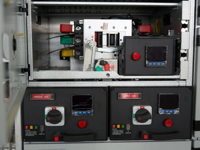
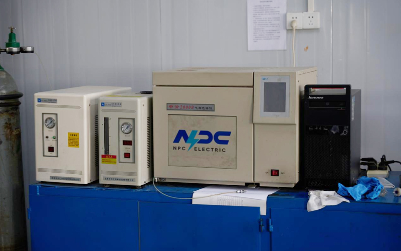
During manufacturing of high voltage switchgear, our multi-stage progress testing ensures every unit meets stringent quality benchmarks before final assembly. Initial tests include dimensional verification of enclosures, busbar alignment checks, and material composition analysis using spectrometry. Mechanical operation tests verify smooth movement of disconnectors, earthing switches, and circuit breakers across 500+ cycles. Insulation resistance testing is performed at multiple production stages using 5kV megger equipment to detect any early defects in bushings and support insulators. Partial discharge measurements are conducted in a shielded chamber to confirm low PD levels below 5pC. Gas tightness testing for GIS models involves helium leak detection with sensitivity up to 10^-9 mbar·L/s. Functional checks of auxiliary circuits, control wiring, and interlock systems are validated according to customer-approved schematics. All test data is digitally recorded and reviewed by quality engineers, with non-conformance items immediately reworked. These progressive inspections maintain consistent quality throughout production.
Design Tests
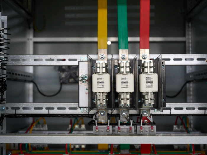
All transformers will be tested after finishing the production, test items as follows:
♦ Insulation Power Factor
♦ Ratio, Polarity, and Phase Relation
♦ Winding Resistance
♦ Impulse Tests
♦ On load Loss Test
♦ No Load Loss Test
♦ Transformer Turns Ratio/TTR (All Tap Voltages)
♦ Impedance Voltage & Load Loss (Rated Voltage)
♦ Polarity, 1-Ph / Phase Relation, 3-Ph (Rated Voltage)
♦ Excitation & No-Load Loss (Rated Voltage)
♦ Applied Voltage
♦ Induced Voltage
♦ Lightning Impulse
♦ Insulation Resistance (Rated Voltage)
♦ Temperature Rise
♦ Dielectric Withstand (Hipot)
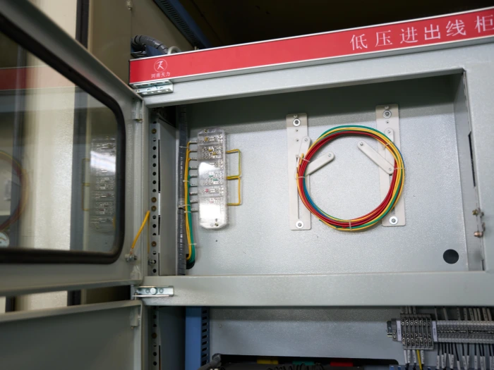
Factory Acceptance Test
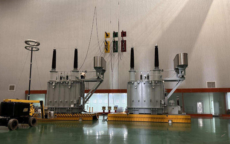
Factory Acceptance Testing for high voltage switchgear integrated with power transformers includes comprehensive verification of combined system performance. Tests begin with visual and dimensional inspection followed by insulation power factor testing on bushings and transformer-switchgear interfaces. No-load and load loss measurements are conducted alongside temperature rise tests at rated current. Dielectric tests encompass applied voltage and induced voltage withstand, with partial discharge monitoring throughout. Switching impulse and lightning impulse tests validate the BIL rating of the complete assembly. Ratio, polarity, and vector group verification ensure correct transformer integration. Control and protection scheme testing includes simulation of fault conditions and verification of trip signals to the HV switchgear. All measurements are performed in accredited labs with calibrated instruments traceable to national standards.
Routine Test - Circuit Breaker Timing & Motion Analysis
Purpose of Testing
Evaluate the integrity of the main circuit insulation and contact connections. Identify potential defects such as moisture ingress, aging, or contamination in the insulation system, and verify that contact resistance is within acceptable limits to prevent overheating.
Testing Equipment
For Insulation Resistance: Megohmmeter (typically 2500V or 5000V DC).For Circuit Resistance: Micro-ohmmeter (DC resistance tester) or Precision DC current source.Auxiliary Tools: Thermometer/hygrometer (for temperature correction).
Pre-Test Preparation
Ensure the switchgear is de-energized, isolated, and properly grounded. Clean the test terminals and bushings to remove dust or moisture. For insulation tests, discharge all capacitive loads (cables, busbars) thoroughly through the grounding switch or shorting links.
Test Progress
1. Insulation Test: Connect the megger leads to the busbar phases and ground. Apply the test voltage (e.g., 2500V DC) and hold for 1 minute.2. Circuit Resistance Test: Connect the micro-ohmmeter current leads to the main busbar or circuit breaker terminals. Pass a low DC current (e.g., 100A) and record the voltage drop.
Temperature Correction
Correct the measured insulation resistance to a standard reference temperature (typically 20°C) using the appropriate exponential formula to ensure compliance with standards across different ambient conditions.
Circuit Resistance Test
Connect the tester leads to the main busbar or circuit breaker terminals. Pass a low DC current (e.g., 100A or 200A as per standard) and accurately record the voltage drop across the connection point. Ensure the equipment is energized only if it complies with specific hot-line testing safety protocols, otherwise perform cold-resistance measurement after de-energization
Mechanical Characteristic Test
Purpose: To verify the operational performance and timing of the circuit breaker mechanism, ensuring compliance with speed and travel requirements for arc extinction.Procedure: Use a dedicated Circuit Breaker Mechanical Tester. Connect the tester to the control circuit (closing/opening coils) and the secondary side of the travel transducer. Perform several opening and closing operations without load. Record key parameters: Opening/Closing time, Synchronization between three phases, Travel distance, Overshoot, and Contact pressure.
Power Frequency Withstand Test (AC Hipot)
Purpose: To validate the integrity of the main insulation system under high voltage stress.Equipment: AC high voltage test set.Procedure: Energize the equipment and apply the specified power frequency test voltage (e.g., 42kV for 1 minute for 10kV switchgear) between phases/inter-phase and ground. Monitor the leakage current. The test is considered passed if the insulation does not break down and the current remains stable within the standard limit. (Note: This is a destructive test; perform only on de-energized and properly discharged equipment).
Partial Discharge (PD) Measurement
Purpose: To identify internal insulation defects such as voids, cracks, or contamination that are not detectable by insulation resistance tests.Procedure: Inject the test voltage up to 1.3~1.5 times the rated voltage. Use a PD detector connected to the coupling capacitor or directly to the test object to measure the apparent charge (pC). Ensure the background noise level is below the detection threshold. Analyze the PD patterns to locate the faulty chamber.
*These comprehensive tests ensure that each transformer meets performance standards and operates
reliably under various conditions.
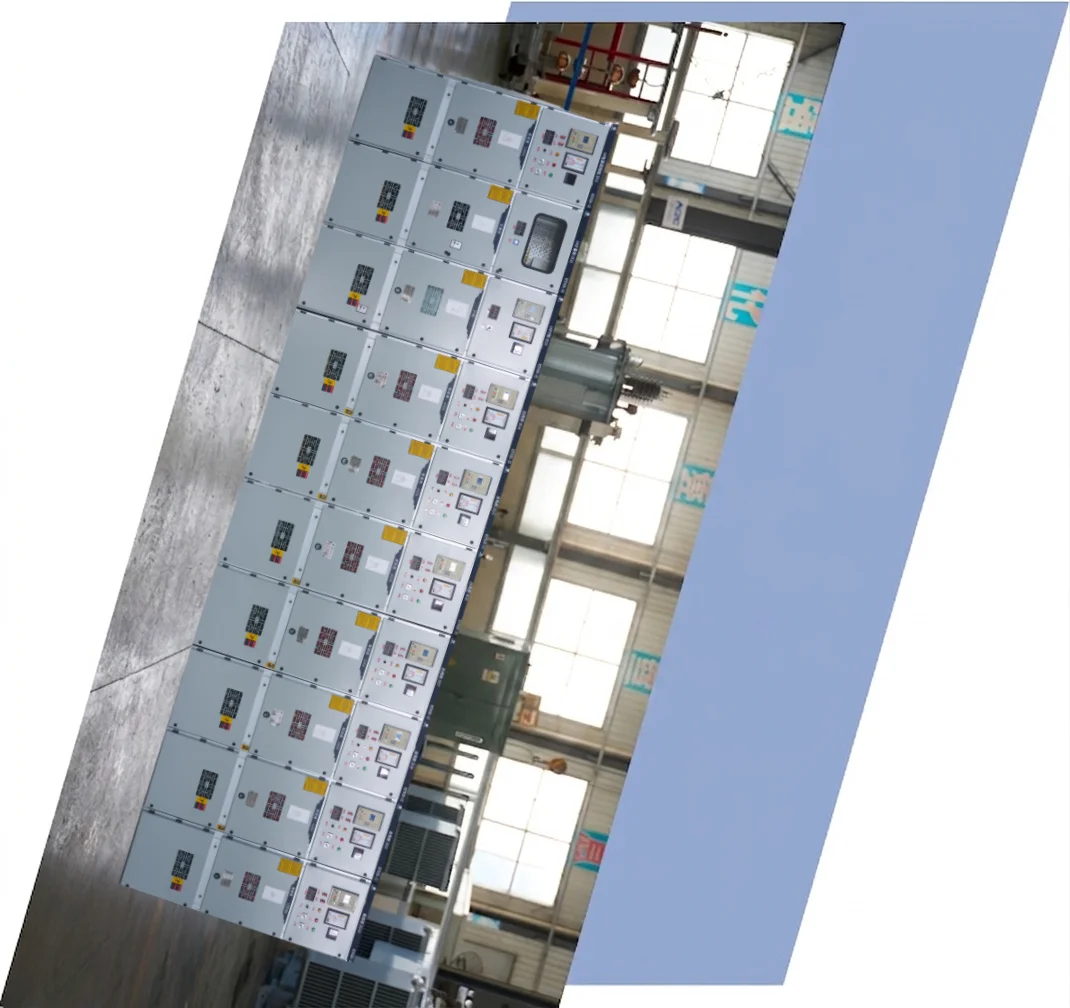
Application
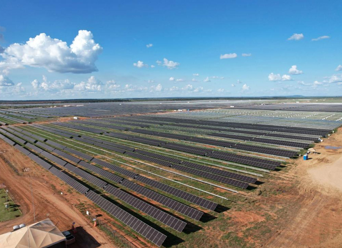
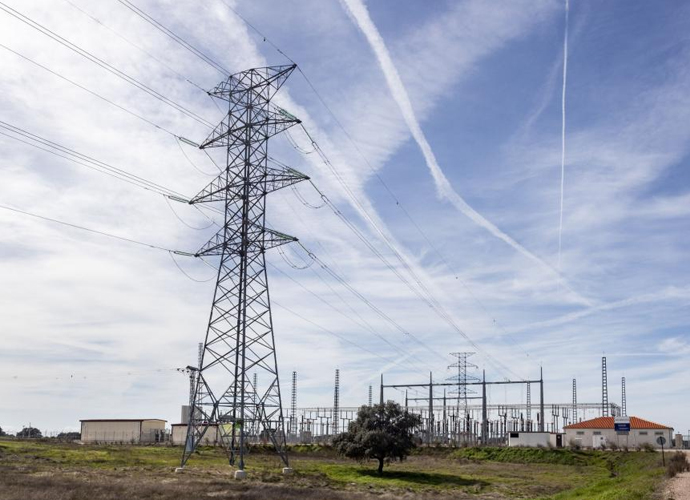
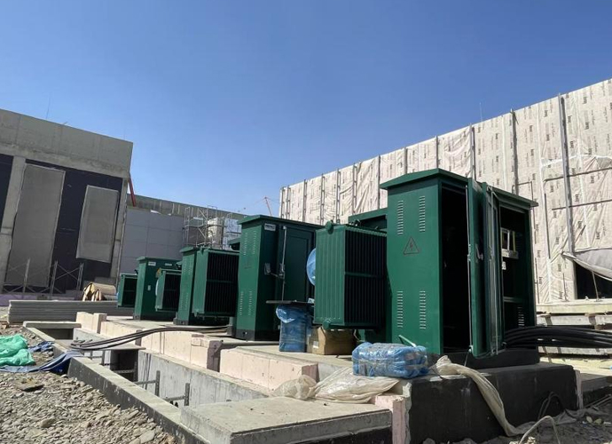
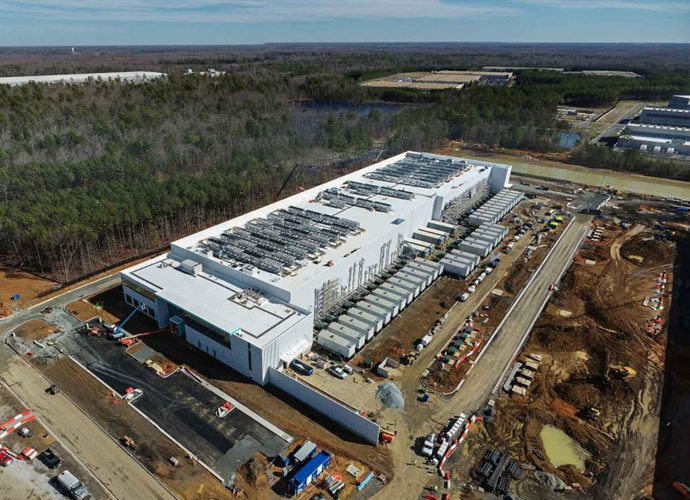
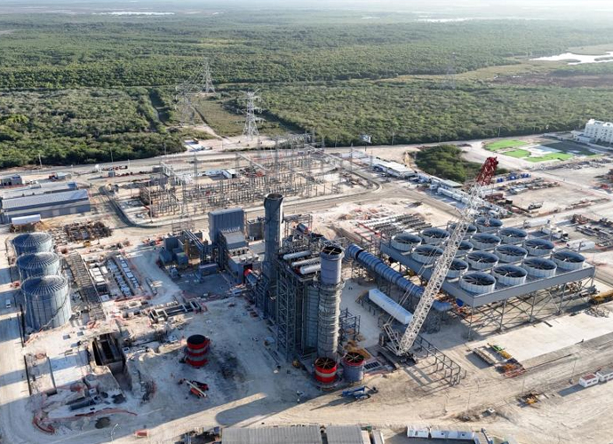
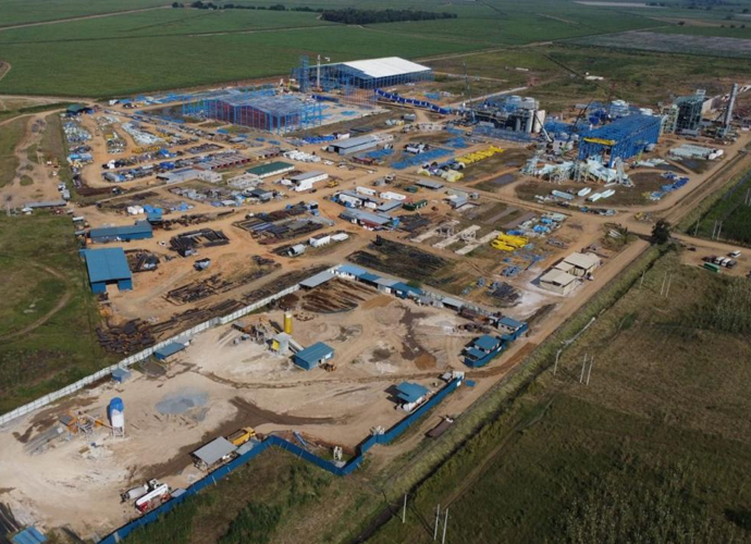
High voltage switchgear is essential in urban substations for reliable power distribution, renewable energy collection stations for wind and solar farms, heavy industrial plants including steel and chemical facilities, and mining operations requiring robust fault protection. It also serves data center backup systems and large commercial complexes needing uninterrupted power supply.


Technical Advantages
● 30+ years of manufacturing experience
● ISO and UL certified production
● Customized cable and transformer solutions

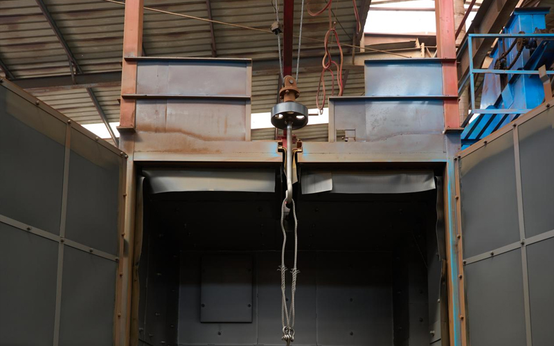
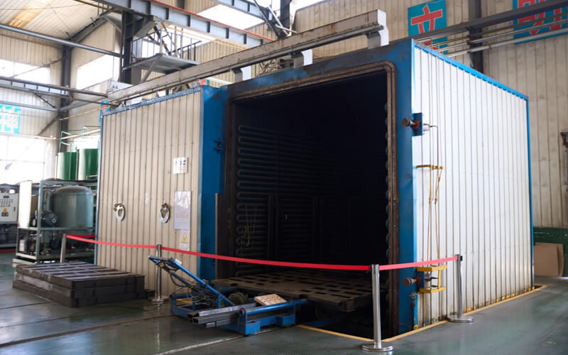
Product Packaging
Transformers Packaging (1)
Transformers Packaging (2)
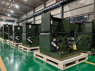
Transformers Packaging (3)
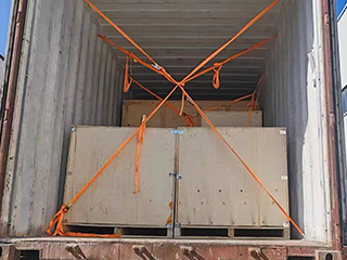
Transformers Packaging (4)
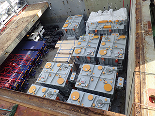
Transformers Packaging (5)
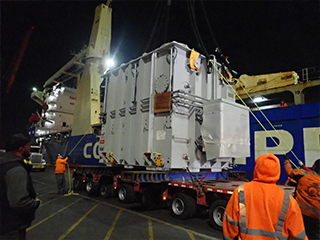
Transformers Packaging (6)
Transformers Packaging (7)
Transformers Packaging (8)
Related Products
SVR-3 Type Three Phase Automatic Step Voltage Regulator
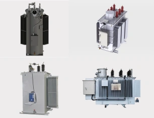
The SVR-3 Type Three Phase Automatic Step Voltage Regulator is a state-of-the-art on-load tap changing device engineered to provide precise, automatic voltage stabilization for medium-voltage distribution networks. Featuring premium copper windings, high-permeability silicon steel cores, and a fast-response motorized tap changer, the SVR-3 delivers accurate voltage correction with minimal disturbance. Its intelligent digital controller continuously monitors three-phase voltage and automatically adjusts taps to maintain stable output even under rapid load changes. Designed for harsh outdoor conditions, it offers excellent overload capability, low power loss, and comprehensive protection including over/under voltage, overload, short-circuit, and phase imbalance. With remote SCADA/GSM monitoring capability and robust sealed-tank construction, the SVR-3 significantly improves voltage profile, reduces line losses, and enhances overall power quality in distribution systems.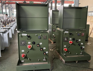
167kVA Conventional Type Single Phase Pole Mounted Transformer
NPC ELECTRIC'S 167kVA Single Phase pole Mounted transformer is a high capacity single phase distribution transformer designed for medium to high load distribution systems. It is mainly used in residential, commercial, agricultural and light industrial applications to provide stable single phase power to ensure reliable operation of user-side equipment. It complies with international standards such as ANSI/IEEE C57, IEC60076 and other standards to ensure its high quality and stability. Standard features include mineral oil insulation (ONAN cooling), aluminum or copper windings, primary voltages 2.4kV–34.5kV grounded wye or delta (common: 7200/12470GrdY, 7620/13200GrdY, 12470GrdY/7200, 24940GrdY/14400, 34500GrdY/19920), secondary 120/240V or 240/120V split-phase (options for 277V/480V or custom), BIL ratings 95–150kV HV / 30kV LV, impedance typically 1.5–4.5%, ±2×2.5% or 5-position tap changer, conventional or CSP (completely self-protected) configurations with internal fuses, lightning arresters, weak-link protection, pressure relief valve, oil sight gauge, and ANSI 70 gray tank finish. Efficiency typically reaches 99.33% at 50% load per DOE levels (with 2029 amendments targeting further reductions for units ≥100 kVA), with low sound levels and corrosion-resistant hardware for extended outdoor service.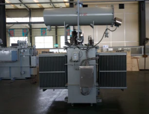
40kV 50MVA Oil Immersed Three-Phase MV&HV Power Transformer Copper
The 40kV 50MVA Oil Immersed Three-Phase MV&HV Power Transformer Copper is engineered for large-scale transmission and industrial substations. Equipped with high-purity copper windings, ONAN/ONAF cooling, and ±8×1.25% on-load tap changer, it achieves ultra-low losses (S13/S14 series). Fully compliant with IEC 60076 and GB/T 1094, it withstands 200 kV lightning impulse and PD <10 pC. Robust corrugated-fin tank with detachable radiators ensures excellent thermal performance under continuous heavy load. Typical voltages: 40±8×1.25%/11kV or 40/6.3kV. Vacuum oil filling and nitrogen sealing guarantee 35+ years of reliable, maintenance-free operation in harsh environments. Trusted by utilities and EPC contractors worldwide.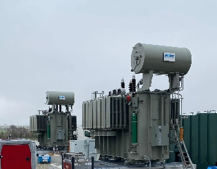
170kV 4–40MVA Oil-Immersed High-Voltage Power Transformer
The 170kV 4–40MVA oil-immersed high-voltage power transformer is designed to support flexible capacity requirements across modern transmission and substation systems. Its wide MVA range allows a single platform to adapt to diverse grid configurations, from regional substations to industrial power interfaces. The transformer utilizes a refined oil-paper insulation system to ensure strong dielectric performance and long-term operational stability under high electrical stress. Advanced magnetic circuit optimization minimizes losses while maintaining excellent voltage regulation. The mechanical structure is engineered to withstand thermal cycling, short-circuit forces, and continuous operation under variable load conditions. With a focus on reliability, efficiency, and service life, this transformer is well suited for utility-scale projects that demand dependable high-voltage energy transfer with adaptable power ratings.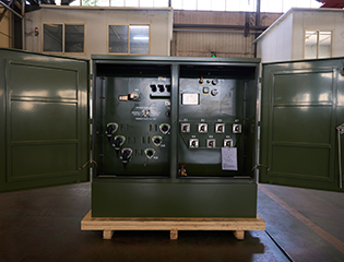
2500kVA Three Phase Pad Mounted Transformer
NPC ELECTRIC's 2500kVA Three Phase Pad Mounted Transformer is a high-performance, oil-immersed distribution transformer engineered for reliable outdoor installation on concrete pads. Compliant with ANSI/IEEE C57, DOE 2016 efficiency standards, and IEC guidelines, this 2.5 MVA unit delivers superior energy efficiency, low losses, and robust durability in demanding utility and industrial environments. Featuring a fully sealed, tamper-resistant enclosure with dead-front or live-front design options, it ensures maximum safety, minimal maintenance, and aesthetic integration in urban settings.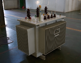
75kVA Oil Immersed Transformer
75kVA oil-immersed transformer is an efficient and reliable power conversion device, which is widely used in power distribution systems in industrial, commercial, and construction sites. The transformer adopts oil-immersed cooling technology, has good heat dissipation performance, and can work continuously and stably under high load conditions. The 75kVA oil-immersed transformer also has complete protection functions, including overload protection, short-circuit protection, and temperature monitoring, to ensure the safety and stability of the equipment during operation.FAQ From Customers
-
What is a Transformer?A transformer is an electrical device used to change the voltage of alternating current (AC). It works on the principle of electromagnetic induction, converting high-voltage current into low-voltage current or low-voltage current into high-voltage current. Transformers are widely used in power transmission, distribution systems, and various electronic devices.
-
What are the main uses of a transformer?The main use of a transformer is voltage conversion. Transformers are used in power transmission systems to help transfer electricity from power plants to consumers. In addition, transformers are also used in electronic devices such as chargers, televisions, power adapters, etc., to adjust the voltage to meet the requirements of different devices.
-
Do you have UL listed?Yes, our transformer has UL listed. We have exported to America many pad mounted transformer,substation transformer and HV.
Welcome your inquiry
Honesty, Integrity, Frugality, Activeness and Passion