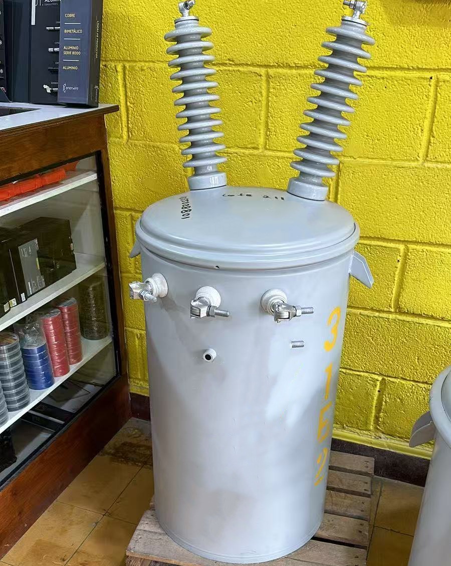
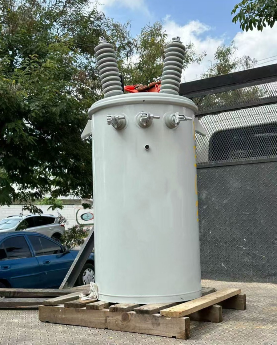
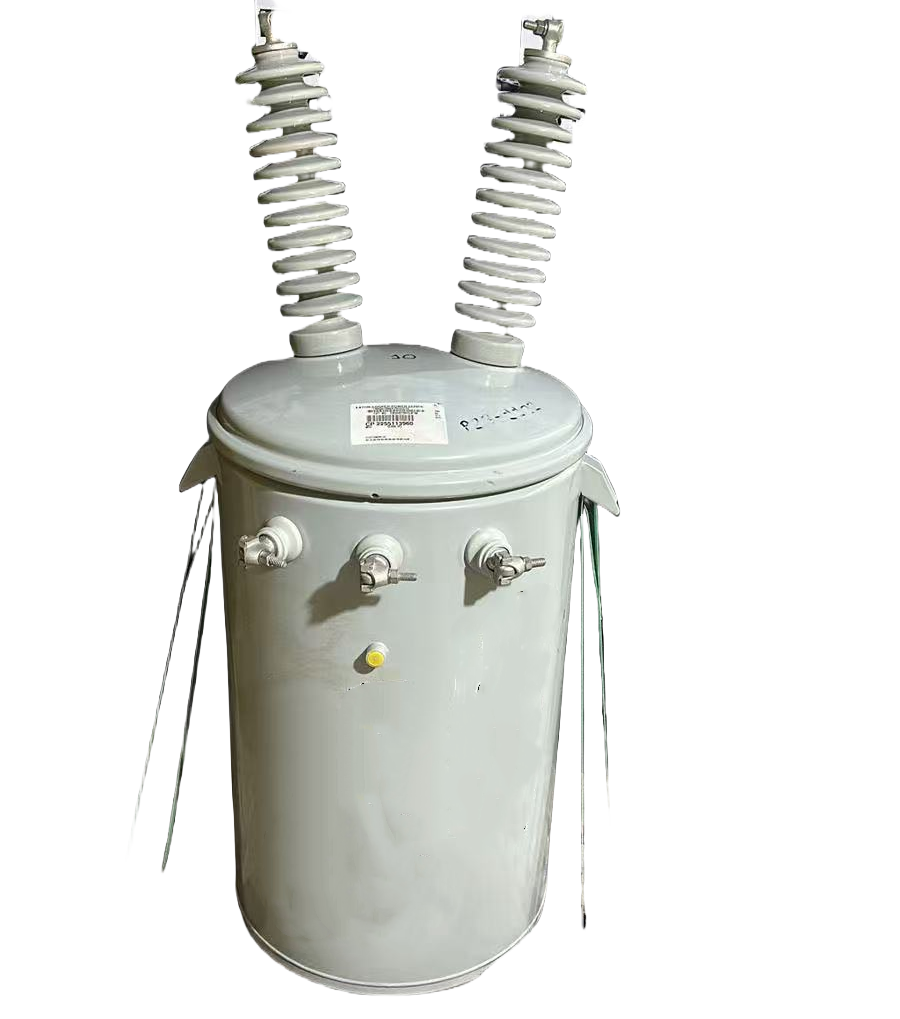


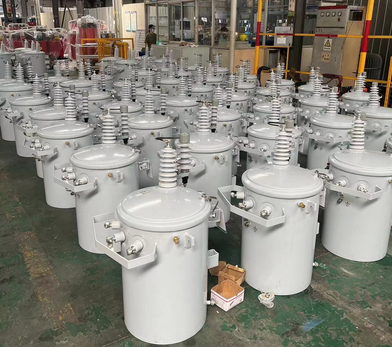
250kVA Single Phase Pole Mounted Transformer
Engineered for heavy-duty overhead applications, the 250kVA single phase pole mounted transformer provides dependable voltage transformation from primary levels like 12.47kV, 24.94kV, or 34.5kV to secondary outputs such as 120/240V or 277/480V. Featuring grain-oriented silicon steel cores for minimal core losses and robust windings, it achieves high efficiency while adhering to DOE energy standards and IEEE C57.12.20 guidelines. The corrugated tank design promotes superior heat dissipation, paired with ONAN self-cooling and a 65°C temperature rise for sustained performance under peak demands. Weather-resistant construction includes lifting lugs, pressure relief devices, and surge protection options, ensuring longevity in exposed environments. This transformer minimizes maintenance needs and supports stable power supply with low noise and excellent overload capability, making it a preferred choice for expanding grid infrastructure.
- Primary Voltage Ratings 2.4kV, 11kV, 33kV, 34.5kV
- Secondary Voltage Ratings 480-240/240-120 or customized
- H.V. Tap Range ± 2×2.5% HV taps or others
- Type Conventional Type
- BIL 30-150kV
- Standards IEEE, ANSI, NEMA, ASTM
- Application workshops, public amenities, managing increased loads
- Power Rating 250kVA
- Certificate CE, ISO
- Cooling Method ONAN, KNAN
- Oil Mineral Oil or FR3
- Opeartion Step Down
Technical Specifications
Customization Optional
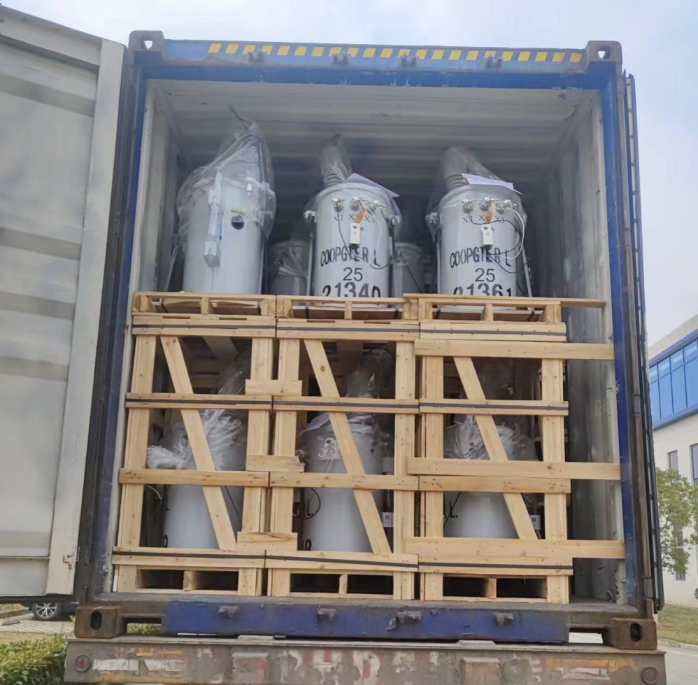
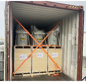
Packing and Shipping
Manufacturer Test
Routine Testing
Application
Technical Specifications
250kVA Single Phase Pole Mounted Transformer
Technical Specifications
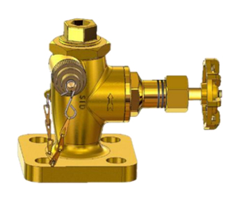
Accessories
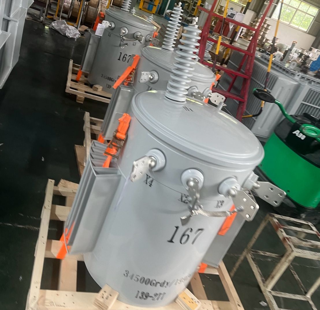
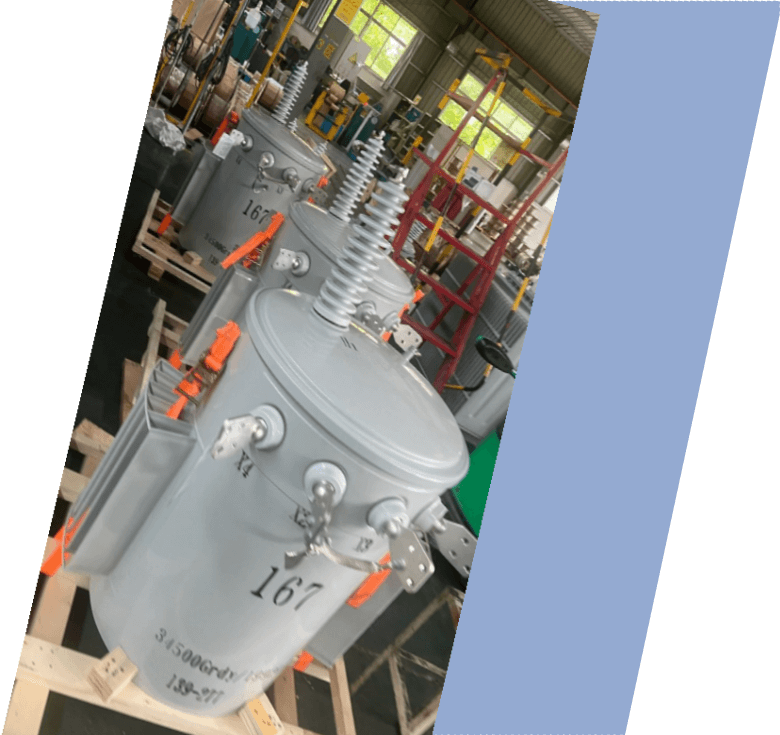
| Rated Power | 250kVA |
| Rating Primary Voltage | 12.4-34.5kV |
| Secondary Voltage | 480-240V 240-120V 277V Customized |
| Frequency | 50/60Hz |
| Vector Group | Ii0,Ii6 |
| Winding Material | Aluminum/Copper |
| Efficiency | As IEEE,Doe 2016,CAS Std or Customized |
| Impedance Voltage | Nominal 2% or Customized 1.1-5.75% |
| Altitude | ≤1,000m or Customized |
| Color | ANSI 70 Light gray/Munsell 7GY3.29/1.5 or customized etc |
| Tank material | Mild Steel, 304 Stainless Steel |
| Insulating Oil Weight | 168 kg |
| Total Weight | 780 kg |
| Outline Dimensions(W×D×H) | 825×910×1635 (mm) |
| Lifting Lug |
| Tap Changer |
| Pressure Relief Valve |
| Tank Cover and clamp |
| L.V Bushing |
| HV Bushing |
| Ground Strap |
| Nameplate |
| Non-PCB decal |
| High Voltage Warning Signs |
| Suport lug |
| Oil fill valve |
Customization Optional
250kVA Single Phase Pole Mounted Transformer
Tailor the 250kVA single phase pole mounted transformer to exact project specifications with comprehensive customization features designed for optimal integration and performance. Primary voltage selections span 2.4kV to 34.5kV, encompassing common ratings like 12.47kV, 13.8kV, 22.9kV, or 33kV, while secondary voltages include 120/240V, 240/480V, 277V, or custom low-voltage configurations to match local utility requirements. Opt for aluminum windings to reduce weight and cost or copper for enhanced conductivity and thermal performance in high-load scenarios. Frequency compatibility covers both 50Hz and 60Hz operations, with cooling upgrades from standard ONAN to hybrid systems incorporating fans for demanding climates. Multi-position off-circuit tap changers, typically ±2x2.5% or more, enable precise voltage adjustment on-site. Impedance customization from 4% to 5.5% optimizes fault current handling, and protective elements such as internal fuses, lightning arresters, or wildlife guards can be added for enhanced safety. Environmentally friendly alternatives include FR3 natural ester fluid for superior fire resistance and biodegradability compared to conventional mineral oil. These bespoke configurations boost energy efficiency, extend operational lifespan, and ensure seamless compatibility with existing overhead lines, catering to utilities focused on reliability, cost savings, and regulatory compliance in diverse installations.
Additional enhancements encompass tank modifications like reinforced mounting brackets for high-wind areas or anti-corrosion coatings for coastal regions. Integrate monitoring accessories such as oil temperature indicators, pressure gauges, or remote sensors for proactive maintenance. Slight capacity adjustments around 250kVA allow for future expansion, while advanced core designs reduce no-load losses further. Bushing options support various insulation levels up to 150kV BIL, and enclosure features can include enhanced ventilation or sound-dampening elements. These flexible options make the 250kVA single phase pole mounted transformer adaptable to challenging conditions, delivering superior power quality, reduced downtime, and long-term value for overhead distribution networks in residential clusters, rural expansions, or light commercial zones.

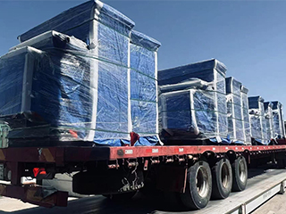
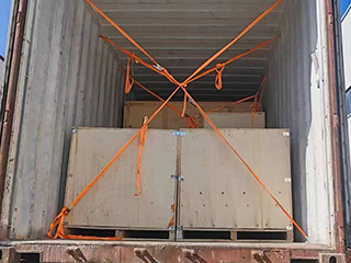
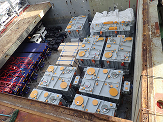
Packing and Shipping
250kVA Single Phase Pole Mounted Transformer
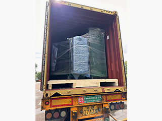
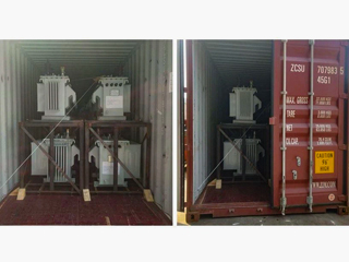
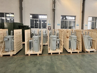
The 250kVA single phase pole mounted transformer is packaged with utmost care using export-grade wooden pallets and reinforced crates constructed from fumigated timber and steel bands to withstand heavy handling. Internal protective layers include dense foam inserts, wooden blocking, and vibration-dampening materials to secure the unit against transit shocks. Moisture control is achieved through vacuum sealing, desiccant packs, and nitrogen blanketing to preserve oil quality and prevent internal corrosion. Partial oil drainage during shipping, combined with sealed bushings and ports, ensures safety, while external labels detail handling precautions, center of gravity, and hazardous classifications. This rigorous packing protocol protects critical components like bushings and taps, guaranteeing the transformer arrives undamaged and ready for quick commissioning.
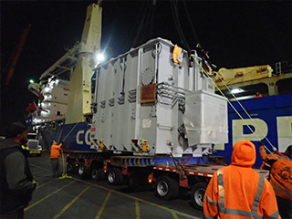
Transportation arrangements are customized for efficiency and security, with domestic shipments via specialized lowboy trailers equipped with securement chains and weatherproof covers to shield from road debris and elements. International consignments typically employ 40-foot open-top or flat-rack containers for oversized units, supplemented by lashing systems compliant with maritime standards. For urgent deliveries, air charter options are coordinated, though surface routes predominate due to dimensions. Continuous GPS tracking, coupled with comprehensive cargo insurance, provides peace of mind throughout the journey. Strict adherence to IEC, IEEE, and local regulations streamlines customs procedures, accelerating delivery timelines for the 250kVA single phase pole mounted transformer globally.
Our commitment to sustainability influences packing choices, favoring recyclable woods and minimal plastic usage while optimizing load configurations to lower transportation emissions. Impact monitors are affixed to crates to detect excessive forces, supporting post-arrival inspections and claims if required. Accessories such as radiators or control boxes are separately crated with individual checklists for easy verification. Partnering with logistics providers experienced in electrical apparatus ensures compliance with heavy-haul permits and safe routing through varied terrains.
Upon arrival, detailed instructions guide safe unloading and reassembly, including oil refilling procedures and torque values for connections. We offer coordination for on-site delivery, even to remote locations, minimizing installation delays. This end-to-end approach safeguards product integrity, reduces risks, and supports efficient deployment of the 250kVA single phase pole mounted transformer in critical power infrastructure projects worldwide.
32
32 years of industry experience
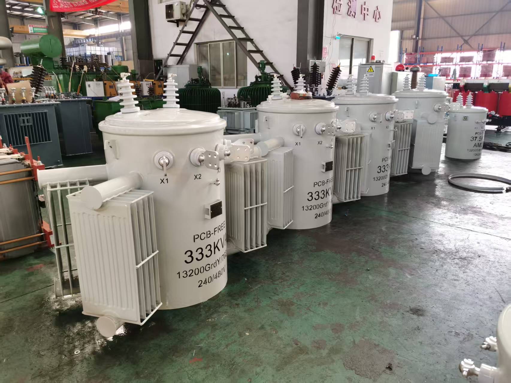
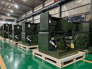
Manufacturer Test
250kVA Single Phase Pole Mounted Transformer
Progress Test
Throughout the production phases of the 250kVA single phase pole mounted transformer, progress tests commence with core material validation, assessing grain-oriented silicon steel for lamination thickness uniformity and surface insulation using epstein frame measurements to maintain no-load losses below specified limits. Winding process checks include turn counting accuracy and layer insulation verification via high-potential testing between consecutive layers at reduced voltage. Interwinding capacitance and dissipation factor are monitored during assembly to detect anomalies early. Ratio verification employs precision ratio meters on preliminary windings, ensuring deviations stay within 0.1% of design values. Core clamping pressure is gauged to prevent buckling, with vibration tests simulating transport stresses. Oil compatibility sampling confirms dielectric strength above 35kV and low moisture levels under 10ppm. Tank fabrication inspections use dye penetrant and radiographic methods on welds for leak-proof integrity, while mounting provisions are load-tested for structural soundness. All measurements are recorded digitally for traceability and trend analysis.
Design Tests
All transformer will be test after finished the production, test items as below:
♦ Insulation Power Factor
♦ Ratio, Polarity, and Phase Relation
♦ Winding Resistance
♦ Impulse Tests
♦ On load Loss Test
♦ No Load Loss Test
♦ Leak Test
♦ DC Insulation Resistance Test
♦ Transformer Turns Ratio/TTR (All Tap Voltages)
♦ Impedance Voltage & Load Loss (Rated Voltage)
♦ Polarity, 1-Ph
♦ Excitation & No-Load Loss (Rated Voltage)
♦ Insulation Resistance (Rated Voltage)
♦ Temperature Rise
♦ Dielectric Withstand (Hipot)
Transformer Factory Acceptance Test
The factory acceptance test sequence for the 250kVA single phase pole mounted transformer initiates with comprehensive visual and dimensional verification against approved drawings, including tank finish, bushing alignment, and accessory placement. Winding DC resistance is measured using four-wire method at stabilized temperatures, corrected to 75°C with results within 1% of factory averages. Turns ratio and polarity are confirmed via automated TTR equipment across all tap positions, maintaining accuracy to 0.25%. Insulation power factor and capacitance testing at 10kV yields dissipation factors below 0.4%, indicating sound dielectric condition. No-load loss and exciting current measurements at rated voltage verify compliance with efficiency mandates, keeping excitation below 1.5% of rated current. Load loss determination through short-circuit method calculates total losses and impedance percentage precisely. Power frequency withstand voltage applies 50kV or equivalent to HV side for one minute without flashover. Induced potential test at higher frequency checks turn insulation integrity. Oil quality analysis includes breakdown voltage over 40kV and dissolved gas levels within acceptable norms.
Routine Test - Leak Test
Purpose of Testing
The purpose of water leakage test is to check whether there is leakage in the equipment or system, to ensure that it has good sealing and safety during use. The integrity of the equipment can be verified by simulating the pressure or load conditions in the working environment.
Testing Equipment
Leakage current tester (e.g. Fluke, Hioki, Megger, etc.)
Voltage source (usually 500V, 1 KV or 2.5 KV, customized according to test requirements)
Temperature and humidity meter
Ground electrode
Voltage source (usually 500V, 1 KV or 2.5 KV, customized according to test requirements)
Temperature and humidity meter
Ground electrode
Pre-Test Preparation
Ensure that the test environment conditions are suitable for leak testing. Test between 20°C and 30°C. Relative humidity should be less than 75% to avoid moisture affecting the test equipment and results.
Test Progress
Connect the Test Instrument:
Properly connect the test equipment (such as a leak detector) to the pipe, container or sealing structure of the device under test.
Apply Test Voltage:
Apply the appropriate test pressure (e.g. 10 bar, 15 bar, etc.) depending on the equipment's operating pressure or test standard.
Properly connect the test equipment (such as a leak detector) to the pipe, container or sealing structure of the device under test.
Apply Test Voltage:
Apply the appropriate test pressure (e.g. 10 bar, 15 bar, etc.) depending on the equipment's operating pressure or test standard.
Measure and Record
Start the test and record the following parameters:
Applied test pressure
Leakage (can be monitored by flow meter or other equipment)
Time record (to ensure that the test time meets the standard requirements)
Initial pressure and final pressure (if any changes)
Applied test pressure
Leakage (can be monitored by flow meter or other equipment)
Time record (to ensure that the test time meets the standard requirements)
Initial pressure and final pressure (if any changes)
Check for leaks
Check for leaks on equipment surfaces and joints by using a foam detector, gas leak detector, or other suitable method.
Repeat Testing (if necessary)
If the test finds leakage or there is any doubt, repeat the test as necessary to verify the sealing of different locations or different equipment parts.
Evaluation Criteria (Reference)
No leakage (excellent): No leakage during the test, the equipment is completely sealed.
Minor leakage (good): Very small leakage is allowed, and it is necessary to judge whether it is qualified according to industry standards.
Minor leakage (good): Very small leakage is allowed, and it is necessary to judge whether it is qualified according to industry standards.
*These comprehensive tests ensure that each transformer meets performance standards and operates
reliably under various conditions.
Application
The 250kVA single phase pole mounted transformer performs effectively in extensive rural electrification projects combined with agricultural demands, stepping down high-voltage lines to power multiple farms, irrigation systems, and remote homesteads while integrating with hybrid solar setups for consistent supply.


Technical Advantages
● 30+ years of manufacturing experience
● ISO and UL certified production
● Customized cable and transformer solutions


Product Packaging
Transformers Packaging (1)
Transformers Packaging (2)
Transformers Packaging (3)
Transformers Packaging (4)
Transformers Packaging (5)
Transformers Packaging (6)
Transformers Packaging (7)
Transformers Packaging (8)
Related Products
250kVA Single Phase Pad Mounted Transformer
NPC ELECTRIC 250 kVA single phase pad mounted transformer operates safely, reliably, and efficiently and can be installed indoors and outdoors. The industrial transformer has a rated power of 250 kVA, a primary voltage of 27600/16000V single-phase and a secondary voltage of 120/240V single-phase.The transformer has a primary loop feed and dead front primary connections.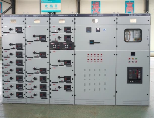
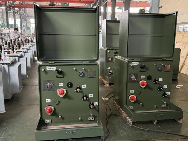
High Voltage Switchgear
NPC Electric high voltage switchgear delivers exceptional reliability and safety for modern electrical networks. Built with cutting-edge insulation technology and intelligent monitoring systems, this HV switchgear ensures seamless power distribution while protecting critical infrastructure from faults and overloads. Ideal for utilities, industrial plants, and renewable energy projects, it combines compact design with robust construction to minimize downtime and maximize operational efficiency in demanding environments.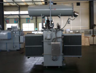
45kV 2500kVA Weatherproof & Oven-Proof Oil-Immersed Power Transformer
The 45kV 2500kVA Weatherproof & Oven-Proof Oil-Immersed Power Transformer is engineered for demanding outdoor applications requiring high durability, stable voltage transformation, and long-term operational reliability. Designed with premium cold-rolled silicon steel, high-conductivity copper windings, and a reinforced oil-immersed cooling system, the transformer ensures excellent thermal stability and resistance to overheating. Its oven-proof construction allows the unit to withstand high ambient temperatures, while the weatherproof enclosure provides protection against rain, dust, humidity, and corrosive environments. With advanced insulation, strong short-circuit endurance, and compatibility with both off-load and on-load tap changers, this 45kV outdoor transformer is ideal for substations, industrial facilities, renewable energy sites, and long-distance power distribution systems. Built in accordance with IEC 60076 standards, it delivers efficiency, reliability, and lifespan required for critical grid infrastructure.
125kVA Cast Resin Dry Type Transformer 3 Phase 10kV/0.4kV Copper Winding IEC Certified
The 125kVA Cast Resin Dry Type Transformer is a compact, three-phase, high-efficiency indoor power transformer engineered for safe and reliable voltage transformation in commercial, institutional, and light-to-medium industrial environments. Featuring advanced cast-resin encapsulation and full copper windings, it eliminates oil-related fire hazards, environmental risks, and routine maintenance while delivering superior performance in confined spaces, high-rise buildings, hospitals, schools, data centers, office complexes, and renewable energy tie-in applications. Fully compliant with IEC 60076-11, IEC 60076-1, IEC 60076-3, IEC 60076-5, IEC 60076-20, IEEE C57.12.01, IEEE C57.12.91, UL 1561 (optional), and DOE 2016 efficiency standards.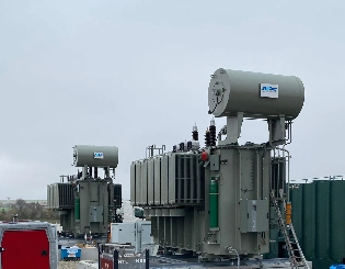
75kV 1250kVA Three Phase Oil Immersed Power Transformer Copper
The 75kV 1250kVA Three Phase Oil Immersed Power Transformer Copper is engineered for regional 66–75 kV transmission and industrial step-down applications. It adopts 99.99 % electrolytic copper windings, high-grade grain-oriented silicon steel S13 core, corrugated tank + ONAN cooling, and ±5 % off-circuit tap changer (on-load optional). Fully compliant with IEC 60076, lightning impulse withstand 350 kV peak, PD <10 pC, noise ≤58 dB. Fully sealed or conservator design with vacuum oil filling and nitrogen sealing ensures >30-year maintenance-free operation even in high-altitude or polluted areas. Ideal for mining, metallurgy, wind farms, and urban 75 kV substations requiring high reliability and low loss.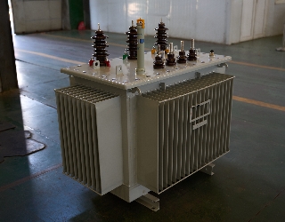
35kV Oil Immersed Transformer
NPC ELECTRIC's 35kV Oil Immersed Transformer is a premium three-phase power transformer optimized for high-voltage step-down in 50/60Hz AC systems with primary ratings of 35kV (or 33-38.5kV range). It incorporates a robust conservator or fully sealed tank design with efficient radiator cooling (ONAN standard, ONAF optional), ensuring exceptional thermal dissipation, moisture exclusion. Outdoor-rated with pollution-resistant bushings (BIL 170-200kV), Dyn11/Ynd1 vector groups, and low noise (<62dB), it provides stable 35kV to secondary voltages (e.g., 10kV/6.3kV/0.4kV) conversion, enhancing grid stability, minimizing transmission losses, and supporting demanding applications in harsh or high-altitude conditions.FAQ From Customers
-
What is a Transformer?A transformer is an electrical device used to change the voltage of alternating current (AC). It works on the principle of electromagnetic induction, converting high-voltage current into low-voltage current or low-voltage current into high-voltage current. Transformers are widely used in power transmission, distribution systems, and various electronic devices.
-
What are the main uses of a transformer?The main use of a transformer is voltage conversion. Transformers are used in power transmission systems to help transfer electricity from power plants to consumers. In addition, transformers are also used in electronic devices such as chargers, televisions, power adapters, etc., to adjust the voltage to meet the requirements of different devices.
-
Do you have UL listed?Yes, our transformer has UL listed. We have exported to America many pad mounted transformer,substation transformer and HV.
Welcome your inquiry
Honesty, Integrity, Frugality, Activeness and Passion