Inside a Power Pole Transformer: Components, Functions, and Design
2025-10-15
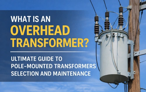
In modern cities and rural areas alike, the power pole transformer plays a crucial role in electrical distribution systems. Often mounted on wooden or concrete utility poles, this device is responsible for stepping down high-voltage electricity from transmission lines to a safe output voltage for homes and businesses. While most people see them daily, few understand what is inside a transformer on a power pole or how it works.
Why Power Pole Transformers Are Needed
Electricity is generated at power plants and transmitted over long distances at high voltages—often tens or hundreds of kilovolts. This reduces energy loss during transmission. However, households and businesses use much lower voltages, typically 120/240 V in North America or 230 V in many other regions.
A power transformer mounted on a distribution pole serves as the critical link between the high voltage electricity in the distribution network and the lower voltages required for end users. Without pole-mounted transformers, the electrical system would be unsafe and unusable for everyday applications.
Major Components Inside a Power Pole Transformer
To understand its function, let’s examine the internal parts of a single-phase power pole transformer:
1. Core
At the heart of the transformer is the magnetic core, typically made of laminated silicon steel. The core provides a low-resistance path for magnetic flux, allowing efficient energy transfer between the primary winding and the secondary winding.
2. Primary and Secondary Windings
- Primary winding: Connected to the high voltage electricity supply (e.g., 7,200 V distribution line).
- Secondary winding: Delivers the stepped-down output voltage (e.g., 120/240 V) to end users.
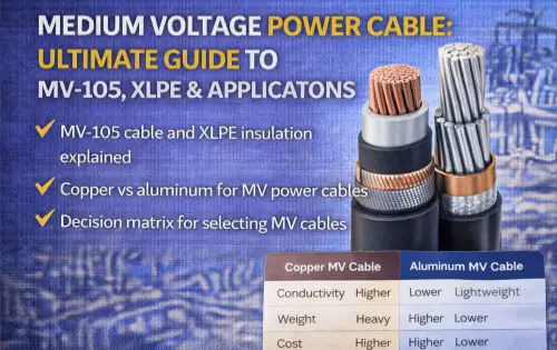
These windings are made of copper or aluminum conductors, carefully insulated to withstand electrical stress. The ratio of turns between the primary and secondary determines the voltage transformation.
3. Electrical Insulation
Insulation ensures that high voltage does not cause dangerous arcing or short circuits. Pole transformers use solid insulation materials (such as paper, pressboard, or epoxy) along with insulating oil to enhance dielectric strength and cooling.
4. Insulating Oil
Most power line transformers are oil-filled. The insulating oil serves two purposes:
- Provides electrical insulation between internal components.
- Removes heat from the core and windings during operation.
5. Bushings and Terminals
Porcelain or polymer bushings connect the internal windings to the external electrical system. These bushings provide a safe passage for conductors while maintaining insulation.
6. Tank and Enclosure
The steel tank protects internal components from weather and mechanical damage. It is sealed to prevent leakage of oil and ingress of moisture.
7. Safety Devices
Some pole transformers include protective fuses, pressure-relief valves, or lightning arresters. These devices prevent failures due to surges, overloading, or internal faults.
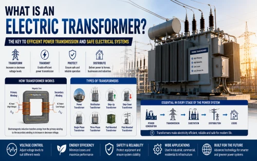
How a Power Pole Transformer Works
The operation is based on Faraday’s law of electromagnetic induction. When high voltage electricity flows through the primary winding, it creates a magnetic field in the core. This changing magnetic flux induces a voltage in the secondary winding.
Because the secondary winding has fewer turns, the voltage is stepped down to a safe level for consumer use. For example:
- Input (primary): 7,200 V (distribution line)
- Output (secondary): 120/240 V (residential supply)
This process conserves power (minus small losses) and enables safe, reliable delivery of electric energy.
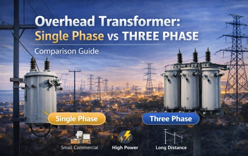
Single-Phase vs. Three-Phase Transformers
Most power pole transformers are single-phase, ideal for residential areas. They can provide two 120 V circuits or one 240 V circuit.
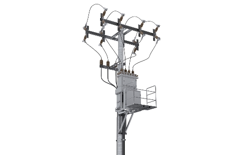
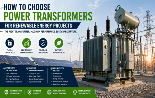
In industrial or commercial settings, multiple single-phase transformers may be combined, or larger three-phase power transformers are used. These systems support higher loads and three-phase machinery.
Role in the Electrical System
The transformer on a power pole is more than just a step-down device—it is an integral part of the electrical system. Its functions include:
- Voltage regulation: Matching supply levels with demand needs.
- Insulation: Isolating consumers from dangerous transmission voltages.
- Load balancing: Distributing energy efficiently across multiple users.
Maintenance and Reliability
Pole-mounted transformers are designed for decades of service, but they require periodic inspection. Common checks include:
- Oil level and quality (to ensure proper electrical insulation).
- Bushing condition.
- Load monitoring.
- External corrosion or leaks.
Failure of a pole transformer can cause localized blackouts, making preventive maintenance essential.
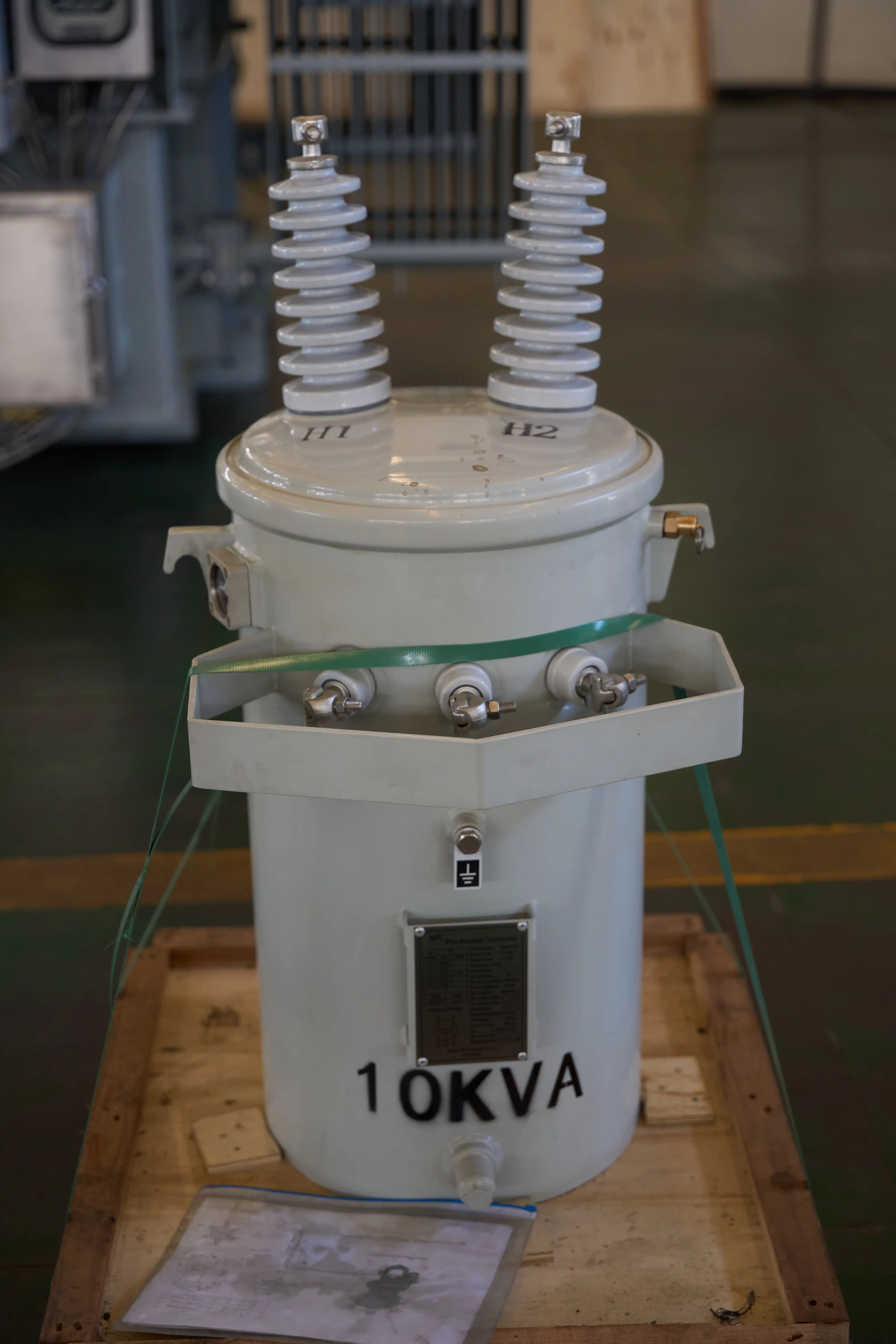
The power pole transformer may look like a simple metal drum on a utility pole, but inside lies a carefully engineered system. With its core and windings, electrical insulation, insulating oil, and protective devices, it ensures safe and efficient transformation of high-voltage electricity into usable electric energy.
By understanding the design and functions of these power transformers, we gain a deeper appreciation for the hidden technology that powers modern life.
Related Articles
Related Products
15kV 3-Layer AAAC/ACSR/AAC Tree Wire - Triple Layer Covered Conductor
The 3-Layer 15kV AAAC/ACSR/AAC Tree Wire is a specialized covered overhead conductor developed for distribution lines in areas with dense vegetation. It uses concentrically stranded AAAC, ACSR, or AAC conductors protected by a triple-layer system of track-resistant HDPE or XLPE. The multi-layer covering delivers exceptional tracking resistance, abrasion protection, and weatherability while greatly reducing the risk of electrical faults from tree limb contact and helping minimize wildfire ignition potential. This advanced design allows closer spacing to vegetation and lowers vegetation management costs. Suitable for conventional overhead or spacer cable systems, the 3-Layer 15kV AAAC/ACSR/AAC Tree Wire offers a cost-effective solution for improving line reliability. It complies with ICEA and ASTM standards and undergoes extensive quality testing to ensure long-term performance and safety.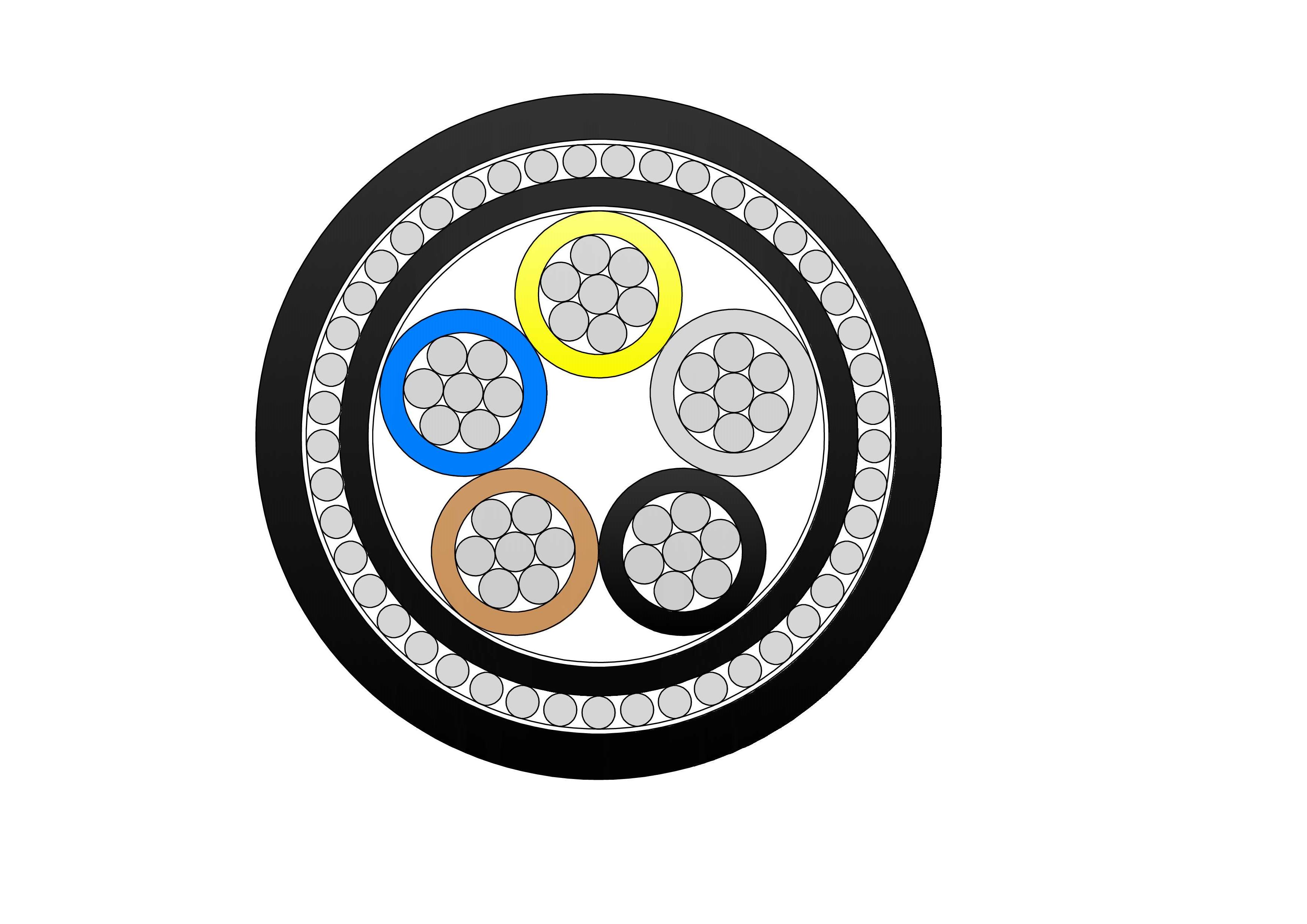
NA2XRY 0.6/1kV Low Voltage Power Cable
NA2XRY 0.6/1kV are low voltage power cables designed according to BS 5467 standard, suitable for fixed installation in indoor, outdoor, underground, or concrete (Can withstand certain mechanical forces) environments. Constructed with aluminium conductors, thermosetting XLPE insulation, PVC inner bedding, double galvanised steel tape armour, and tough PVC outer sheath, it meets IEC 60502-1 requirements. The STA armour offers outstanding resistance to compression and external forces, enabling direct burial. Lightweight aluminium lowers installation costs while ensuring good current rating and low losses. Flame-retardant and stable in harsh conditions, the NA2XRY 0.6/1kV Low Voltage Power Cable is favoured for manufacturing plants, renewable sites, commercial complexes, and infrastructure demanding reliable, low-maintenance low-voltage cabling with enhanced mechanical safeguarding.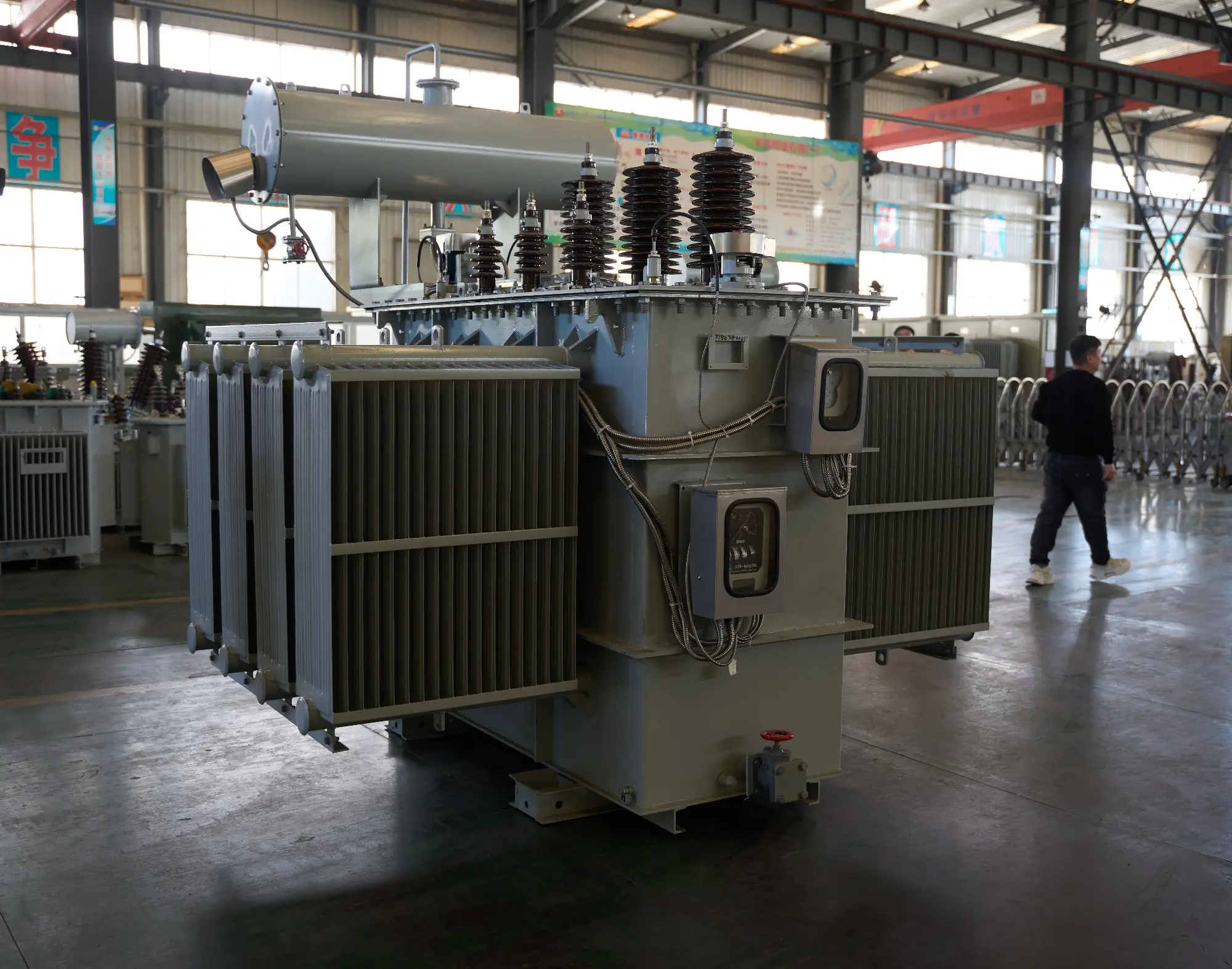
35kV 46kV Power Transformer
NPC ELECTRIC's 35kV and 46kV power(electrical) transformer complies with international standards such as IEC and ANSI, and features high efficiency, low loss, and strong insulation. This product is widely used in power grid main transformers, power plants, industrial and mining enterprises, and large infrastructure projects. Key features include mineral oil or FR3 natural ester insulation (ONAN/ONAF/ODAF cooling options), copper or aluminum windings, primary voltages 35kV or 46kV (grounded wye or delta, with dual-voltage configurations), secondary voltages 6.6kV, 11kV, 13.8kV, 33kV, or custom (e.g., 13.8kV/480V or 35kV/11kV), BIL ratings 200–650kV depending on voltage class, impedance typically 8–12%, ±2×2.5% or ±5% off-load tap changer (OLTC optional), conservator tank or sealed tank design, Buchholz relay, pressure relief device, oil temperature gauges, winding temperature indicators, and ANSI 61 gray or custom tank finish.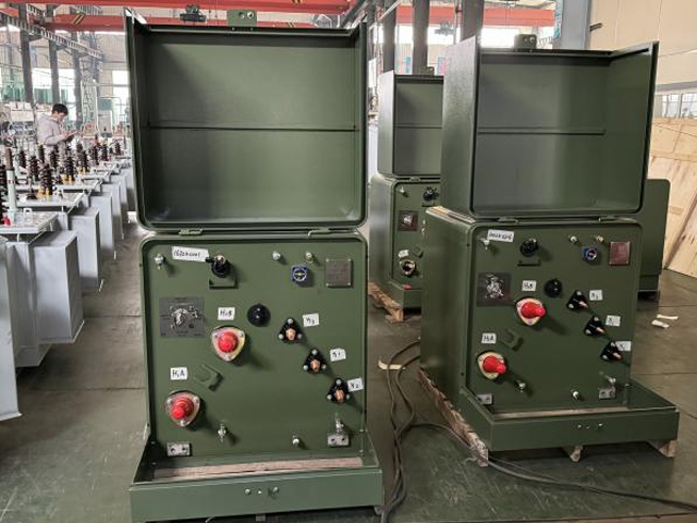
30kVA Single Phase Pole Mounted Transformer
NPC Electric's 30kVA Single Phase Pole Mounted Transformer is a compact, high-efficiency single-phase distribution transformer designed for overhead pole installation in 50/60Hz AC rural and suburban networks, with primary voltages up to 35kV (common 12.47kV/13.2kV/13.8kV/34.5kV) and secondary at 120/240V or 240/480V split-phase. It utilizes a hermetically sealed cylindrical tank with high-strength steel construction and radiator fins for natural oil circulation (ONAN cooling), providing excellent thermal management, corrosion resistance via epoxy coatings, and a maintenance-free lifespan over 25 years. Featuring low-loss grain-oriented silicon steel core for reduced no-load losses (typically 100-150W), high-purity copper windings, and premium mineral insulating oil (IEC 60296 compliant, dielectric strength >45kV/2.5mm), it minimizes load losses (around 500-700W at 75°C), supports overloads up to 125% continuous, operates quietly (<50dB), and achieves efficiency >98.5%. Compliant with IEEE C57.12.20, ANSI C57.12.28, DOE efficiency standards, and CSA C2.1, this transformer optimizes energy distribution, lowers operational costs, and enhances reliability for single-phase residential, farm, and light commercial loads.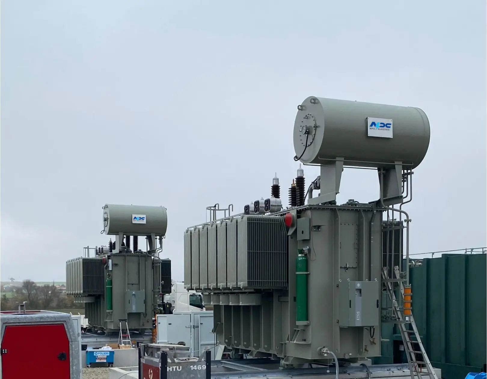
138kV / 140kV / 150kV Three-Phase Oil-Immersed Power Transformer
The 138kV / 140kV / 150kV Three-Phase Oil-Immersed Power Transformer is designed to serve high-voltage transmission and substation applications requiring dependable energy transfer and long-term operational stability. Its design emphasizes electrical reliability, structural strength, and efficient thermal management to support continuous service under varying grid loads. The transformer employs a refined magnetic circuit and carefully engineered winding structure to maintain voltage accuracy while minimizing operational stress. An oil-immersed insulation and cooling system ensures effective heat dissipation and insulation integrity throughout extended operating cycles. Built for outdoor installation, the transformer is capable of withstanding environmental exposure, electrical fluctuations, and mechanical demands associated with modern high-voltage networks. It is suitable for utility-scale projects where safety, efficiency, and durability are essential performance criteria.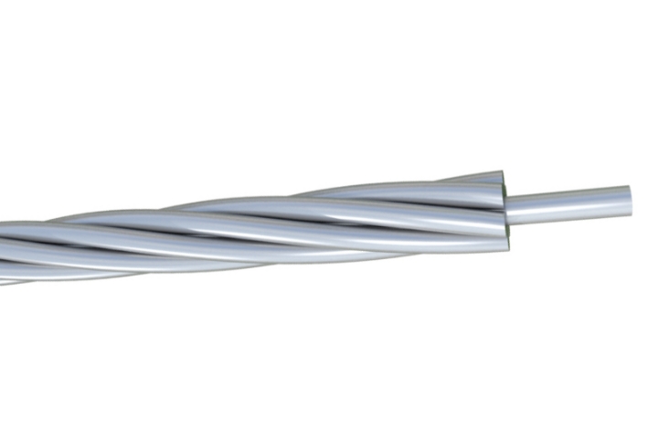
18 Gauge Galvanized Steel Conductor Wire for Fencing & Binding
The 18 Gauge Galvanized Steel Conductor Wire is designed for flexibility, durability, and reliable performance in light-duty applications. Manufactured from high-quality carbon steel and coated with a protective zinc layer through hot-dip galvanization, it offers excellent resistance to corrosion, rust, and environmental exposure. With its thinner 18 gauge diameter, this wire provides superior flexibility while maintaining adequate tensile strength, making it ideal for applications such as agricultural fencing, construction binding, packaging, and general industrial use. The uniform zinc coating ensures long-lasting protection, even in outdoor and humid environments. The smooth and clean surface reduces friction during handling and installation, improving efficiency and safety. Produced under strict quality control procedures and compliant with international standards such as ASTM and IEC, the wire ensures consistent performance. Customization options including zinc coating thickness, tensile strength, and packaging are available to meet specific customer requirements, making it a cost-effective and versatile solution.
22kV Dry Type Transformer Cast Resin Three Phase Distribution Transformer
22kV Dry Type Transformer Cast Resin Three Phase Distribution Transformer, a premium oil-free solution engineered for safe, reliable medium-voltage power distribution in indoor environments. This three-phase cast resin transformer features fully vacuum-impregnated epoxy resin windings with high-conductivity copper conductors and premium low-loss grain-oriented silicon steel cores, achieving superior energy efficiency (typically 98.5%+), significantly reduced no-load and load losses, and excellent partial discharge performance (<10pC). The advanced cast resin encapsulation provides outstanding moisture resistance, self-extinguishing fire safety (F1 class), robust short-circuit withstand capability, and completely maintenance-free operation. Natural air (AN) cooling with optional forced air (AF) upgrades supports high overload capacity, while optimized core clamping, vibration-dampening mounts, and noise-reduction design deliver low acoustic levels suitable for urban or sensitive installations.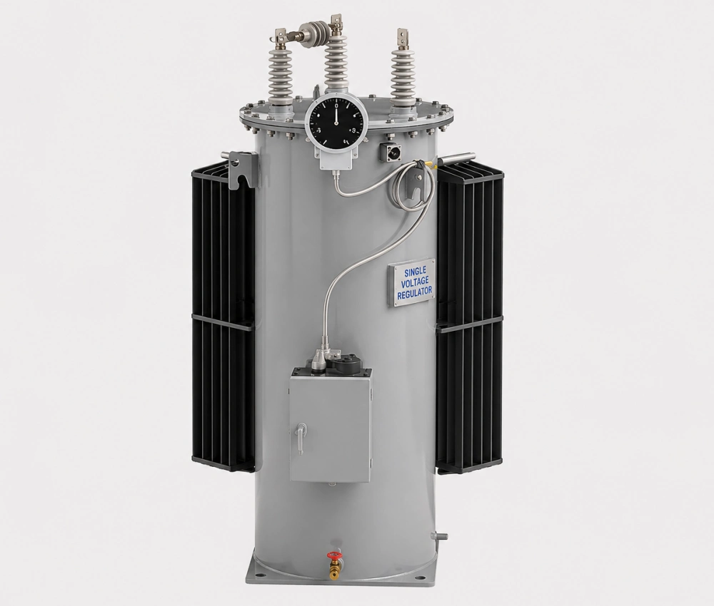
Three Phase Step Voltage Regulator - Distribution Voltage Stabilizer
The Three Phase Step Voltage Regulator is a high-reliability, automatic on-load tap changing device engineered to maintain stable voltage levels in medium-voltage distribution systems. Featuring premium copper windings, advanced low-loss silicon steel cores, and a fast-response motorized tap changer, it delivers precise voltage correction with excellent accuracy and minimal waveform distortion. The intelligent digital AVR controller continuously monitors three-phase parameters and automatically adjusts taps in real time to compensate for load variations and grid fluctuations. Designed for demanding outdoor environments, it offers robust overload capacity, low power losses, comprehensive protection systems, and remote monitoring capabilities. This regulator effectively improves voltage profile, reduces energy losses, and enhances the overall stability and efficiency of distribution networks.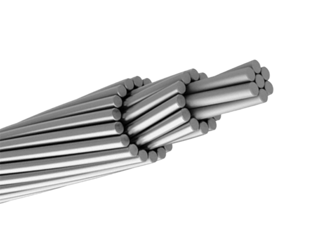
ALL ALUMINUM CONDUCTORS(AAC)
All Aluminum Conductors (AAC) are essential for overhead power transmission and distribution, constructed from concentrically stranded hard-drawn 1350 aluminum wires. Known for their superior electrical conductivity—up to 61.2% IACS—these conductors minimize energy losses, making them cost-effective for urban and rural grids. Lighter than steel-reinforced options, AAC simplifies installation and reduces structural demands on poles and towers. Their excellent corrosion resistance suits moderate environments, though they exhibit higher sag in long spans compared to alloys. Compliant with standards like ASTM B231 and IEC 60889, AAC is available in various sizes, from small distribution lines to higher voltage applications. The stranded design enhances flexibility and durability against wind and ice loads. Ideal for primary and secondary overhead lines, AAC supports efficient power delivery with minimal maintenance. By optimizing conductivity and weight, these conductors contribute to sustainable energy infrastructure, reducing operational costs and enhancing reliability in standard utility setups. Their recyclability aligns with eco-friendly practices in modern electrical networks.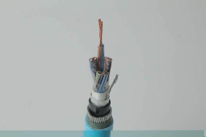
Instrumentation Cables—PVC Insulated,Individual & Overall Screened, Unarmoured PVC Sheathed Cables(CU/PVC/OSCR/PVC)
Instrumentation Cables are multi-conductor cables that carry and transport low-voltage electrical signals. These low-voltage signals are used to control and monitor electrical power systems. Instrumentation cables have many different industrial applications that include broadcasting, equipment control, such as drilling and pumping in the oil and gas industry, and data transfer, which includes analog and digital signals. They are manufactured according to the BS EN 50288-7 and BS EN 50288-1 standards to ensure quality. Instrumentation cables come in twisted pairs, triads, and quads, depending on the customer’s applications; twisting reduces any electromagnetic interference by reducing the chances of electrical voltages and currents being induced in the conductor. Individual and overall screening are also applied in instrumentation cables to optimize the signal transferred and further reduce any electromagnetic interference. Screening of pairs, triads, or quads also includes a drain wire earthed to the ground, which ensures a noise-free signal transmission.
FR-N20XA8E-AR Triplex 12/20kV Cable Gen to NF C 33-226 - AL/XLPE/MDPE
The NF C 33-226 AL-XLPE-MDPE 12/20(24)kV Triplex Cable is a high-quality three-core medium voltage power cable designed for reliable three-phase energy transmission. It is constructed with Class 2 stranded aluminum conductors, cross-linked polyethylene (XLPE) insulation, and a medium-density polyethylene (MDPE) outer sheath, providing excellent electrical performance, thermal stability, and mechanical durability. Manufactured in accordance with NF C 33-226, IEC 60502-2, and EN 60228, this cable is ideal for industrial plants, municipal networks, and commercial power systems. It offers high resistance to water (AD7) and UV radiation (ISO 4892), and is halogen-free (IEC/EN 60754-1), ensuring safe and environmentally friendly operation. With a rated voltage of 12/20 (24)kV and a maximum conductor temperature of 90°C, this AL-XLPE-MDPE Triplex cable ensures efficient, safe, and long-term power transmission in medium-voltage distribution networks.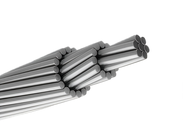
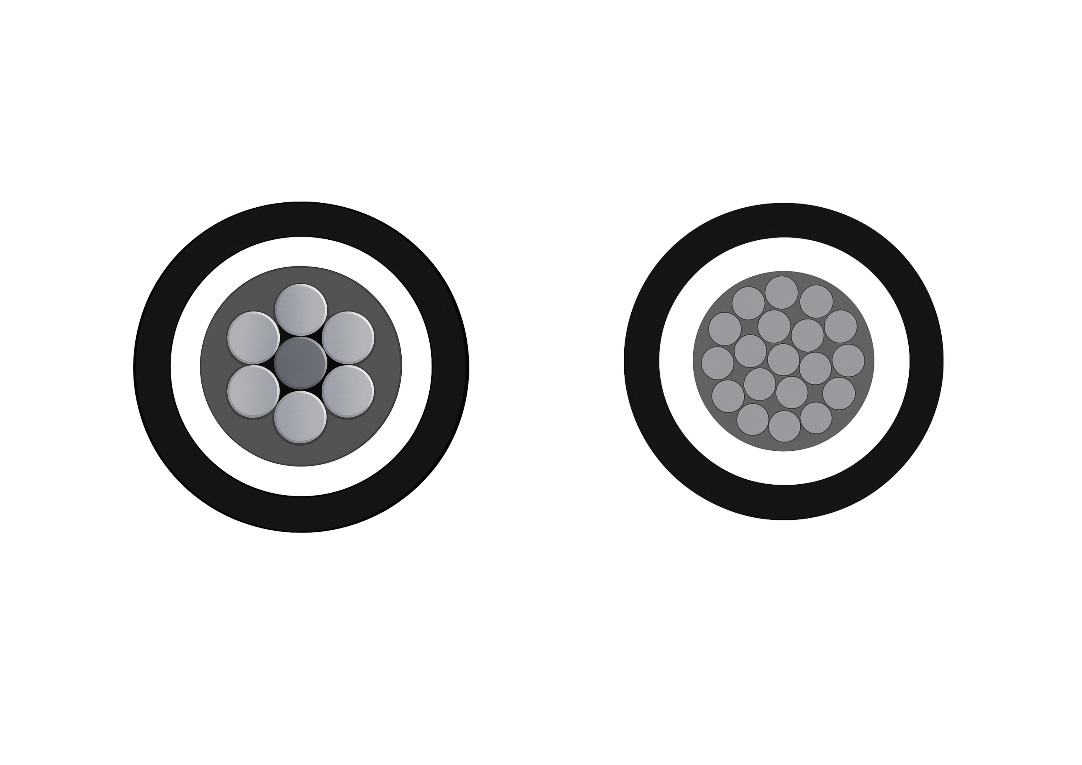
Raven ACSR Conductor Cable
The Raven ACSR Conductor Cable is a reliable overhead conductor designed for efficient power distribution. Named "Raven" for its 1/0 AWG size with 6/1 stranding (6 aluminum wires around 1 steel core), it combines lightweight aluminum for high conductivity with a galvanized steel core for tensile strength. Compliant with ASTM B230, B232, and ICEA standards, this cable offers a breaking load of approximately 3,550 lbs and a current rating up to 242 amps at 75°C in overhead applications. The aluminum 1350-H19 provides excellent corrosion resistance and low electrical resistance (0.1662 Ω/1000ft at 20°C), while the steel enhances sag control over spans up to 250m. Suitable for voltages up to 138kV in distribution lines, the Raven ACSR Conductor Cable minimizes line losses and withstands moderate weather loads, including wind and ice. Its economical design is ideal for utility upgrades, rural electrification, and grid extensions, ensuring dependable power delivery with minimal maintenance in overhead transmission and distribution systems worldwide.
Instrumentation Cables—XLPE Insulated,Individual & Overall Screened, Wire Armoured PVC Sheathed Cables(CU/XLPE/IOSCR/SWA/PVC)
Tailored for resilience under thermal and mechanical stress, the Instrumentation Cables—XLPE Insulated, Individual & Overall Screened, Wire Armoured PVC Sheathed Cables (CU/XLPE/IOSCR/SWA/PVC) ensure accurate signal transmission in challenging conditions. Stranded copper conductors offer low resistance and bendability, with XLPE insulation enabling 90°C continuous use and 250°C short-circuit resistance. Dual screening—individual for crosstalk minimization and overall aluminum/polyester with drain wire for EMI/RFI blocking—safeguards data integrity. SWA armour defends against physical hazards, while PVC sheath provides flame resistance and waterproofing. Adhering to BS EN 50288-7 and BS EN 50288-1, these multi-pair/triad cables handle analogue/digital circuits with reduced capacitance, supporting complex systems. Versatile for ducts, direct burial, or outdoor exposures, they improve uptime, cut failures, and enhance efficiency in heat-prone areas. With superior thermal stability and insulation properties, this CU/XLPE/IOSCR/SWA/PVC is essential for professionals needing armoured, dual-screened solutions that minimize costs and maximize performance in industrial sectors.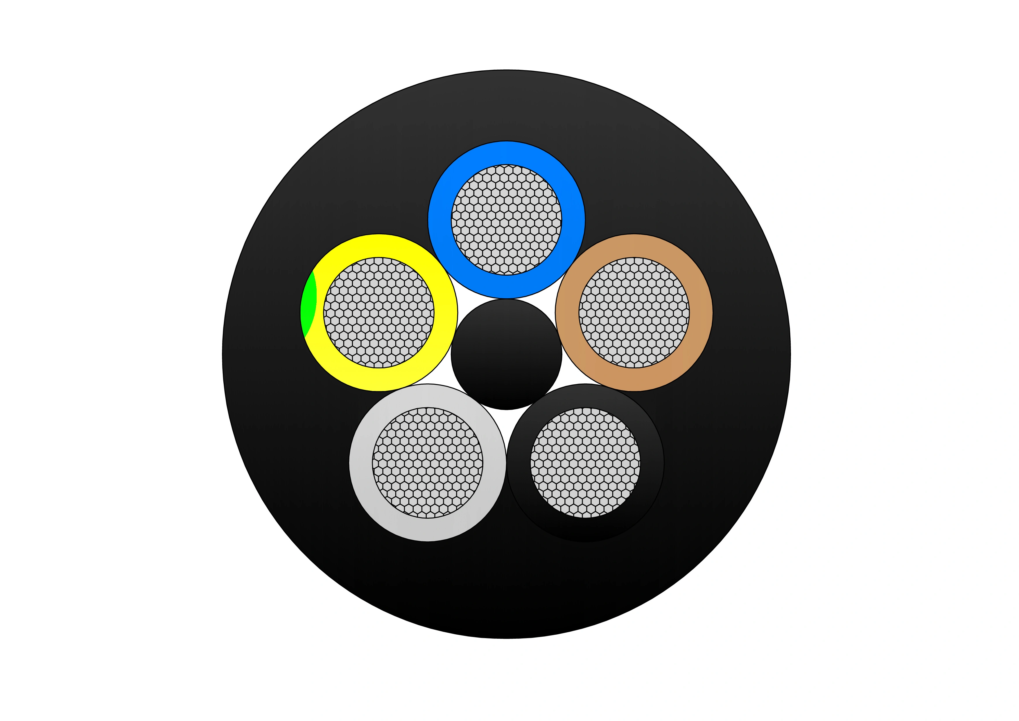
(N)TSCGEWOU 3.6/6kV, 6/10kV, 8.7/15kV and 12/20kV FO Cable
The (N)TSCGEWOU 3.6/6kV, 6/10kV, 8.7/15kV and 12/20kV FO Cable is a flexible, heavy-duty medium-voltage trailing/reeling cable with integrated fiber optic (FO) elements for combined power and high-speed data transmission in mining and tunneling. It features class 5 finely stranded tinned copper phase conductors for flexibility and corrosion resistance, semi-conductive screens, EPR insulation for superior dielectric strength and 90°C rating, copper braid screen for EMI protection and grounding, control conductors, monitoring conductor (ÜL), central or distributed multimode/single-mode fiber optic cores (protected in gel-filled tubes for water resistance and mechanical protection), and a tough rubber outer sheath resistant to oil, flame, abrasion, and mechanical stress. Compliant with DIN VDE 0250 and relevant IEC standards, it supports high tensile loads, fast reeling speeds, and tight bending radii while enabling real-time monitoring and communication. The (N)TSCGEWOU FO ensures safe, reliable MV power and data delivery to mobile equipment like shearers, tunnel boring machines, and smart conveyors in harsh underground environments.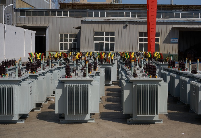
1250kVA Oil Immersed Transformer
NPC ELECTRIC's 1250kVA oil-immersed transformer adopts advanced design and manufacturing technology and complies with international power equipment standards (such as IEC, ANSI, IEEE, etc.). Its high-quality materials and strict quality control ensure the long-term reliability and safety of the equipment. The transformer has high efficiency and stable power transmission performance and is widely used in industrial, commercial, and power systems. With low operating noise and reliable voltage regulation, the transformer is well suited for industrial facilities, commercial complexes, and utility distribution networks.Welcome your inquiry
Honesty, Integrity, Frugality, Activeness and Passion