


Control Cable 0.6/1 kV CVV-S to IEC 60502 Standard (2-30 core)
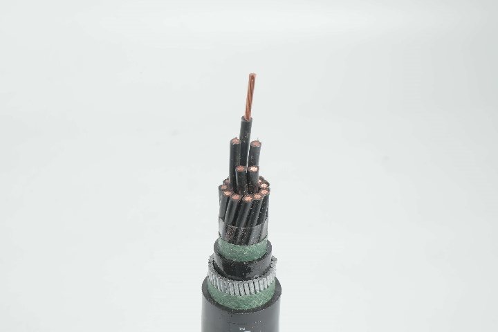
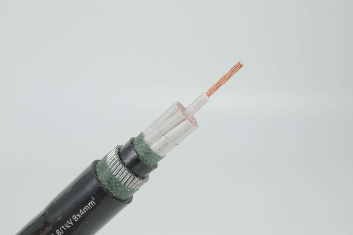
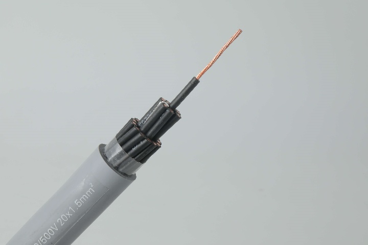
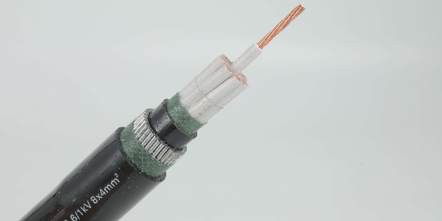
Engineered for electromagnetic interference resistance, the Control Cable 0.6/1 kV CVV-S to IEC 60502 Standard (2-30 core) excels in sensitive control environments. It employs concentric stranded copper conductors for low-resistance transmission, paired with black PVC insulation marked by white numbers for easy identification. The integrated copper tape shield effectively blocks electrostatic noise, while dual PVC sheaths provide flame resistance and mechanical protection. Suitable for 0.6/1 kV ratings, it withstands temperatures from -15°C to 70°C. This cable is tailored for supervisory circuits, outdoor stations, and installations in ducts or conduits where shielding is essential. With options from 2 to 30 cores, it accommodates diverse system requirements, enhancing signal integrity and reducing errors. Fully compliant with IEC 60502, it minimizes operational disruptions in high-interference settings. Ideal for professionals demanding dependable solutions, the CVV-S ensures long-lasting performance and cost savings through superior durability.
- Standard IEC 60502-1, IEC 60228
Construction
Technical Specifications
Quality Control
Application
Construction
Control Cable 0.6/1 kV CVV-S to IEC 60502 Standard
Conductors
Copper or Aluminium conductor, round stranded or Shaped, Class 2 to IEC 60228, BS EN 60228. For smaller sizes, a solid round conductor, Class 1 as per IEC 60228, BS EN 60228, can also be supplied upon request.
Insulation
PVC or XLPE material and thickness shall be as per IEC 60502 or BS 5467, rated for 90°C continuous operation
Colour Code (1)
1 Core: Red or Black
2 Cores: Red, Black
3 Cores: Red, Yellow, Blue
4 Cores: Red, Yellow, Blue, Black
5 Cores: Red, Yellow, Blue, Black, Green
Above 5 Cores: Black Cores with White numerals
2 Cores: Red, Black
3 Cores: Red, Yellow, Blue
4 Cores: Red, Yellow, Blue, Black
5 Cores: Red, Yellow, Blue, Black, Green
Above 5 Cores: Black Cores with White numerals
Colour Code (2)
1 Core: Brown or Blue
2 Cores: Brown or Blue
3 Cores: Brown, Black, Grey
4 Cores: Blue, Brown, Black, Grey
5 Cores: Green/Yellow, Blue, Brown, Black, Grey
Above 5 Cores: Black Cores with White numerals
2 Cores: Brown or Blue
3 Cores: Brown, Black, Grey
4 Cores: Blue, Brown, Black, Grey
5 Cores: Green/Yellow, Blue, Brown, Black, Grey
Above 5 Cores: Black Cores with White numerals
Assembly / Inner Sheath
Two, three, or four insulated conductors are laid up together with non-hygroscopic fillers, and the assembly is bedded with an extruded layer of PVC. In case of non-armoured cables, this layer may be omitted
Armour
Aluminum/Galvanized Steel Wires are applied helically over the bedding as per IEC 60502 or as per BS 5467, BS 6346. Single-core cables shall be Aluminium wire armour.
Aluminum/Steel Tapes are applied helically over the bedding of multi-core cables as per IEC 60502.
Aluminum/Steel Tapes are applied helically over the bedding of multi-core cables as per IEC 60502.
Outer Sheath
Outer sheath shall be of Extruded PVC Type ST2 as per IEC 60502-1 or Type 9 as BS 6346/5467. Special types of PVC sheathing material, such as Fire Retardant PVC, Anti-Termite PVC, Anti-Rodent PVC, Sunlight resistant PVC, and Oil Resistant PVC, are available on special request. Also, special sheathing materials such as LLDPE, MDPE, HDPE, LSF, and CPE are available on request.
Fire Performance of Cable Sheaths
Cables can be supplied with special flame retardant PVC outer sheath to comply with the flame test requirements of IEC 60332-3-22, IEC 60332-3-23, and IEC 60332-3-24, can also supply cables with Low Smoke Halogen Free (LSHF) material according to IEC 60502-1, BS 7211, BS 6724, or other equivalent standards.
Technical Specifications
Control Cable 0.6/1 kV CVV-S to IEC 60502 Standard (2-30 core)
2 Cores, 3 Cores and 4 Cores
5 Cores, 6 Cores and 7 Cores
8 Cores, 9 Cores and 10 Cores
11 Cores, 12 Cores and 13 Cores
14 Cores and 15 Cores
| No. of core |
Nominal cross sectional area |
No.&dia. of wires |
Thickness of insulation |
Thickness of inner sheath |
Thickness of outer sheath |
Overall diameter (Approx.) |
Minimum insulation resistance (at70ºC) |
Cable weight (Approx.) |
Standard Length |
| mm2 | No./mm | mm | mm | mm | mm | Ohm/km | kg/km | m | |
| 2 | 0.5 | 7/0.30 | 0.8 | 1 | 1.8 | 12.5 | 0.0162 | 180 | 500/D |
| 0.75 | 7/0.37 | 0.8 | 1 | 1.8 | 13 | 0.0142 | 195 | 500/D | |
| 1 | 7/0.40 | 0.8 | 1 | 1.8 | 13 | 0.0135 | 205 | 500/D | |
| 1.5 | 7/0.50 | 0.8 | 1 | 1.8 | 14 | 0.0115 | 230 | 500/D | |
| 2.5 | 7/0.67 | 0.8 | 1 | 1.8 | 15 | 0.0093 | 280 | 500/D | |
| 4 | 7/0.85 | 1 | 1 | 1.8 | 17 | 0.0092 | 375 | 500/D | |
| 6 | 7/1.04 | 1 | 1 | 1.8 | 18.5 | 0.0078 | 450 | 500/D | |
| 3 | 0.5 | 7/0.30 | 0.8 | 1 | 1.8 | 13 | 0.0162 | 195 | 500/D |
| 0.75 | 7/0.37 | 0.8 | 1 | 1.8 | 13.5 | 0.0142 | 215 | 500/D | |
| 1 | 7/0.40 | 0.8 | 1 | 1.8 | 13.5 | 0.0135 | 225 | 500/D | |
| 1.5 | 7/0.50 | 0.8 | 1 | 1.8 | 14.5 | 0.0115 | 260 | 500/D | |
| 2.5 | 7/0.67 | 0.8 | 1 | 1.8 | 15.5 | 0.0093 | 325 | 500/D | |
| 4 | 7/0.85 | 1 | 1 | 1.8 | 18 | 0.0092 | 445 | 500/D | |
| 6 | 7/1.04 | 1 | 1 | 1.8 | 19 | 0.0078 | 545 | 500/D | |
| 4 | 0.5 | 7/0.30 | 0.8 | 1 | 1.8 | 13.5 | 0.0162 | 220 | 500/D |
| 0.75 | 7/0.37 | 0.8 | 1 | 1.8 | 14 | 0.0142 | 245 | 500/D | |
| 1 | 7/0.40 | 0.8 | 1 | 1.8 | 14.5 | 0.0135 | 260 | 500/D | |
| 1.5 | 7/0.50 | 0.8 | 1 | 1.8 | 15.5 | 0.0115 | 300 | 500/D | |
| 2.5 | 7/0.67 | 0.8 | 1 | 1.8 | 16.5 | 0.0093 | 385 | 500/D | |
| 4 | 7/0.85 | 1 | 1 | 1.8 | 19 | 0.0092 | 530 | 500/D | |
| 6 | 7/1.04 | 1 | 1 | 1.8 | 20.5 | 0.0078 | 660 | 500/D |
| No. of core |
Nominal cross sectional area |
No.&dia. of wires |
Thickness of insulation |
Thickness of inner sheath |
Thickness of outer sheath |
Overall diameter (Approx.) |
Minimum insulation resistance (at70ºC) |
Cable weight (Approx.) |
Standard Length |
| mm2 | No./mm | mm | mm | mm | mm | Ohm/km | kg/km | m | |
| 5 | 0.5 | 7/0.30 | 0.8 | 1 | 1.8 | 14.5 | 0.0162 | 250 | 500/D |
| 0.75 | 7/0.37 | 0.8 | 1 | 1.8 | 15 | 0.0142 | 280 | 500/D | |
| 1 | 7/0.40 | 0.8 | 1 | 1.8 | 15.5 | 0.0135 | 295 | 500/D | |
| 1.5 | 7/0.50 | 0.8 | 1 | 1.8 | 16.5 | 0.0115 | 345 | 500/D | |
| 2.5 | 7/0.67 | 0.8 | 1 | 1.8 | 18 | 0.0093 | 445 | 500/D | |
| 4 | 7/0.85 | 1 | 1 | 1.8 | 20.5 | 0.0092 | 620 | 500/D | |
| 6 | 7/1.04 | 1 | 1 | 1.8 | 22.5 | 0.0078 | 780 | 500/D | |
| 6 | 0.5 | 7/0.30 | 0.8 | 1 | 1.8 | 15.5 | 0.0162 | 270 | 500/D |
| 0.75 | 7/0.37 | 0.8 | 1 | 1.8 | 16 | 0.0142 | 305 | 500/D | |
| 1 | 7/0.40 | 0.8 | 1 | 1.8 | 16.5 | 0.0135 | 320 | 500/D | |
| 1.5 | 7/0.50 | 0.8 | 1 | 1.8 | 17.5 | 0.0115 | 375 | 500/D | |
| 2.5 | 7/0.67 | 0.8 | 1 | 1.8 | 19 | 0.0093 | 490 | 500/D | |
| 4 | 7/0.85 | 1 | 1 | 1.8 | 22 | 0.0092 | 685 | 500/D | |
| 6 | 7/1.04 | 1 | 1 | 1.8 | 24 | 0.0078 | 865 | 500/D | |
| 7 | 0.5 | 7/0.30 | 0.8 | 1 | 1.8 | 15.5 | 0.0162 | 275 | 500/D |
| 0.75 | 7/0.37 | 0.8 | 1 | 1.8 | 16 | 0.0142 | 315 | 500/D | |
| 1 | 7/0.40 | 0.8 | 1 | 1.8 | 16.5 | 0.0135 | 330 | 500/D | |
| 1.5 | 7/0.50 | 0.8 | 1 | 1.8 | 17.5 | 0.0115 | 395 | 500/D | |
| 2.5 | 7/0.67 | 0.8 | 1 | 1.8 | 19 | 0.0093 | 520 | 500/D | |
| 4 | 7/0.85 | 1 | 1 | 1.8 | 22 | 0.0092 | 730 | 500/D | |
| 6 | 7/1.04 | 1 | 1 | 1.8 | 24 | 0.0078 | 930 | 500/D |
| No. of core |
Nominal cross sectional area |
No.&dia. of wires |
Thickness of insulation |
Thickness of inner sheath |
Thickness of outer sheath |
Overall diameter (Approx.) |
Minimum insulation resistance (at70ºC) |
Cable weight (Approx.) |
Standard Length |
| mm2 | No./mm | mm | mm | mm | mm | Ohm/km | kg/km | m | |
| 8 | 0.5 | 7/0.30 | 0.8 | 1 | 1.8 | 16 | 0.0162 | 310 | 500/D |
| 0.75 | 7/0.37 | 0.8 | 1 | 1.8 | 17 | 0.0142 | 350 | 500/D | |
| 1 | 7/0.40 | 0.8 | 1 | 1.8 | 17 | 0.0135 | 370 | 500/D | |
| 1.5 | 7/0.50 | 0.8 | 1 | 1.8 | 18.5 | 0.0115 | 445 | 500/D | |
| 2.5 | 7/0.67 | 0.8 | 1 | 1.8 | 20 | 0.0093 | 590 | 500/D | |
| 4 | 7/0.85 | 1 | 1 | 1.8 | 23.5 | 0.0092 | 835 | 500/D | |
| 6 | 7/1.04 | 1 | 1 | 1.8 | 25.5 | 0.0078 | 1070 | 500/D | |
| 9 | 0.5 | 7/0.30 | 0.8 | 1 | 1.8 | 17 | 0.0162 | 340 | 500/D |
| 0.75 | 7/0.37 | 0.8 | 1 | 1.8 | 18 | 0.0142 | 390 | 500/D | |
| 1 | 7/0.40 | 0.8 | 1 | 1.8 | 18 | 0.0135 | 415 | 500/D | |
| 1.5 | 7/0.50 | 0.8 | 1 | 1.8 | 19.5 | 0.0115 | 495 | 500/D | |
| 2.5 | 7/0.67 | 0.8 | 1 | 1.8 | 21.5 | 0.0093 | 660 | 500/D | |
| 4 | 7/0.85 | 1 | 1 | 1.8 | 25 | 0.0092 | 945 | 500/D | |
| 6 | 7/1.04 | 1 | 1 | 1.8 | 27.5 | 0.0078 | 1215 | 500/D | |
| 10 | 0.5 | 7/0.30 | 0.8 | 1 | 1.8 | 18 | 0.0162 | 370 | 500/D |
| 0.75 | 7/0.37 | 0.8 | 1 | 1.8 | 19 | 0.0142 | 425 | 500/D | |
| 1 | 7/0.40 | 0.8 | 1 | 1.8 | 19.5 | 0.0135 | 445 | 500/D | |
| 1.5 | 7/0.50 | 0.8 | 1 | 1.8 | 20.5 | 0.0115 | 540 | 500/D | |
| 2.5 | 7/0.67 | 0.8 | 1 | 1.8 | 23 | 0.0093 | 720 | 500/D | |
| 4 | 7/0.85 | 1 | 1 | 1.8 | 27 | 0.0092 | 1030 | 500/D | |
| 6 | 7/1.04 | 1 | 1 | 1.8 | 29.5 | 0.0078 | 1325 | 500/D |
| No. of core |
Nominal cross sectional area |
No.&dia. of wires |
Thickness of insulation |
Thickness of inner sheath |
Thickness of outer sheath |
Overall diameter (Approx.) |
Minimum insulation resistance (at70ºC) |
Cable weight (Approx.) |
Standard Length |
| mm2 | No./mm | mm | mm | mm | mm | Ohm/km | kg/km | m | |
| 11 | 0.5 | 7/0.30 | 0.8 | 1 | 1.8 | 18.5 | 0.0162 | 395 | 500/D |
| 0.75 | 7/0.37 | 0.8 | 1 | 1.8 | 19.5 | 0.0142 | 455 | 500/D | |
| 1 | 7/0.40 | 0.8 | 1 | 1.8 | 20 | 0.0135 | 480 | 500/D | |
| 1.5 | 7/0.50 | 0.8 | 1 | 1.8 | 21 | 0.0115 | 580 | 500/D | |
| 2.5 | 7/0.67 | 0.8 | 1 | 1.8 | 23.5 | 0.0093 | 780 | 500/D | |
| 4 | 7/0.85 | 1 | 1 | 1.8 | 28 | 0.0092 | 1125 | 500/D | |
| 6 | 7/1.04 | 1 | 1 | 1.8 | 30.5 | 0.0078 | 1450 | 500/D | |
| 13 | 0.5 | 7/0.30 | 0.8 | 1 | 1.8 | 19 | 0.0162 | 435 | 500/D |
| 0.75 | 7/0.37 | 0.8 | 1 | 1.8 | 20 | 0.0142 | 505 | 500/D | |
| 1 | 7/0.40 | 0.8 | 1 | 1.8 | 20.5 | 0.0135 | 530 | 500/D | |
| 1.5 | 7/0.50 | 0.8 | 1 | 1.8 | 22 | 0.0115 | 645 | 500/D | |
| 2.5 | 7/0.67 | 0.8 | 1 | 1.8 | 24.5 | 0.0093 | 875 | 500/D | |
| 4 | 7/0.85 | 1 | 1 | 1.8 | 29 | 0.0092 | 1275 | 500/D | |
| 6 | 7/1.04 | 1 | 1 | 1.8 | 32 | 0.0078 | 1665 | 500/D | |
| 13 | 0.5 | 7/0.30 | 0.8 | 1 | 1.8 | 19 | 0.0162 | 435 | 500/D |
| 0.75 | 7/0.37 | 0.8 | 1 | 1.8 | 20 | 0.0142 | 505 | 500/D | |
| 1 | 7/0.40 | 0.8 | 1 | 1.8 | 20.5 | 0.0135 | 530 | 500/D | |
| 1.5 | 7/0.50 | 0.8 | 1 | 1.8 | 22 | 0.0115 | 645 | 500/D | |
| 2.5 | 7/0.67 | 0.8 | 1 | 1.8 | 24.5 | 0.0093 | 875 | 500/D | |
| 4 | 7/0.85 | 1 | 1 | 1.8 | 29 | 0.0092 | 1275 | 500/D | |
| 6 | 7/1.04 | 1 | 1 | 1.9 | 32 | 0.0078 | 1665 | 500/D |
| No. of core |
Nominal cross sectional area |
No.&dia. of wires |
Thickness of insulation |
Thickness of inner sheath |
Thickness of outer sheath |
Overall diameter (Approx.) |
Minimum insulation resistance (at70ºC) |
Cable weight (Approx.) |
Standard Length |
| mm2 | No./mm | mm | mm | mm | mm | Ohm/km | kg/km | m | |
| 14 | 0.5 | 7/0.30 | 0.8 | 1 | 1.8 | 19 | 0.0162 | 435 | 500/D |
| 0.75 | 7/0.37 | 0.8 | 1 | 1.8 | 20 | 0.0142 | 505 | 500/D | |
| 1 | 7/0.40 | 0.8 | 1 | 1.8 | 20.5 | 0.0135 | 540 | 500/D | |
| 1.5 | 7/0.50 | 0.8 | 1 | 1.8 | 22 | 0.0115 | 660 | 500/D | |
| 2.5 | 7/0.67 | 0.8 | 1 | 1.8 | 24.5 | 0.0093 | 900 | 500/D | |
| 4 | 7/0.85 | 1 | 1 | 1.8 | 29 | 0.0092 | 1305 | 500/D | |
| 6 | 7/1.04 | 1 | 1 | 1.9 | 32 | 0.0078 | 1715 | 500/D | |
| 15 | 0.5 | 7/0.30 | 0.8 | 1 | 1.8 | 20 | 0.0162 | 475 | 500/D |
| 0.75 | 7/0.37 | 0.8 | 1 | 1.8 | 21 | 0.0142 | 550 | 500/D | |
| 1 | 7/0.40 | 0.8 | 1 | 1.8 | 21.5 | 0.0135 | 585 | 500/D | |
| 1.5 | 7/0.50 | 0.8 | 1 | 1.8 | 23 | 0.0115 | 715 | 500/D | |
| 2.5 | 7/0.67 | 0.8 | 1 | 1.8 | 25.5 | 0.0093 | 980 | 500/D | |
| 4 | 7/0.85 | 1 | 1 | 1.8 | 30.5 | 0.0092 | 1425 | 500/D | |
| 6 | 7/1.04 | 1 | 1 | 1.9 | 34 | 0.0078 | 1875 | 500/D |
Quality Control
Control Cable 0.6/1 kV CVV-S to IEC 60502 Standard (2-30 core)
Raw Material Test
For the Control Cable 0.6/1 kV CVV-S to IEC 60502 Standard (2-30 core), raw material testing ensures top-tier quality. Step 1: Verify copper conductor purity using atomic absorption spectrometry to meet 99.99% standards per IEC 60228. Step 2: Test PVC insulation for tensile strength (≥12.5 N/mm²) and elongation (≥150%) with universal testing machines. Step 3: Evaluate copper tape for thickness and conductivity via micrometer and resistivity checks. Step 4: Assess sheath compounds for flame retardancy through oxygen index testing (>27%). Step 5: Conduct chemical resistance immersion tests on PVC in oils and acids for 168 hours. All steps involve 10% batch sampling, detailed logging, and rejection of substandard items to align with IEC 60502, guaranteeing shielded reliability and durability in the final product.
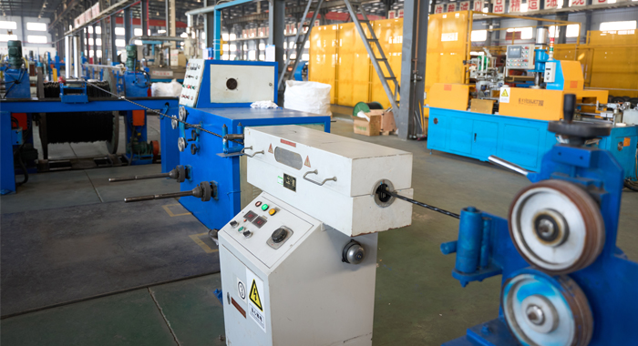
Process inspection
Process inspection of the Control Cable 0.6/1 kV CVV-S to IEC 60502 Standard (2-30 core) focuses on shielding application. Step 1: Control stranding parameters with dynamometers to avoid breaks. Step 2: Monitor insulation uniformity via ultrasonic thickness gauges. Step 3: Verify core lay and identification accuracy. Step 4: Apply copper tape and inspect coverage with eddy current testers. Step 5: Run continuity and voltage tests during assembly. Step 6: Check sheath extrusion for smoothness using sensors. Step 7: Sample sections every 300 meters for cross-analysis. Step 8: Maintain audit-ready digital records. This detailed oversight, per IEC 60502, prevents defects and ensures optimal EMI protection in the finished cable.
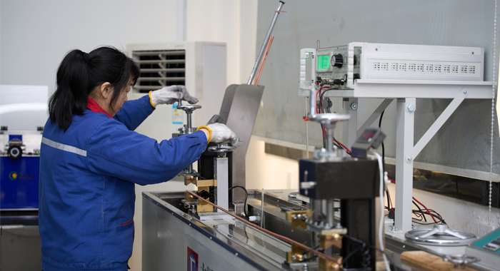
Finished Product
Finished testing for the Control Cable 0.6/1 kV CVV-S to IEC 60502 Standard (2-30 core), verifying shielding efficacy. Step 1: Apply 3 kV AC tests for insulation verification. Step 2: Measure DC resistance for conductor performance. Step 3: Conduct shielding attenuation tests against EMI. Step 4: Perform flex and torsion cycles for durability. Step 5: Test thermal stability at 90°C. Step 6: Assess water ingress on sheaths. Step 7: Evaluate overall electrical properties. Step 8: Issue compliance certificates post-inspection. Batch-wide testing with calibrated instruments confirms IEC 60502 standards, ensuring reliable EMI-resistant operation.
Application
This Control Cable 0.6/1 kV CVV-S to IEC 60502 Standard (2-30 core) thrives in EMI-prone settings like factory control panels, renewable energy systems, commercial wiring, and transportation infrastructure. It offers shielded reliability in wet/dry conduits and outdoor exposures, ideal for precise instrumentation and machinery controls.


Technical Advantages
● 30+ years of manufacturing experience
● ISO and UL certified production
● Customized cable and transformer solutions


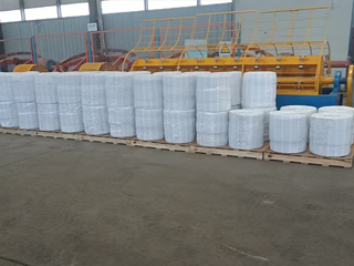
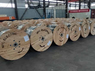
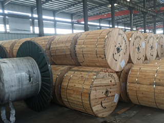
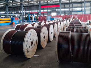
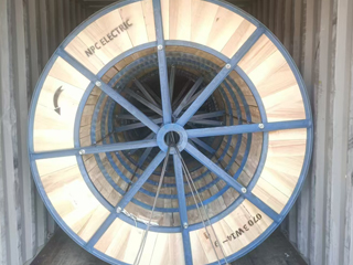
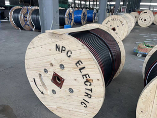
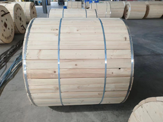
Product Packaging
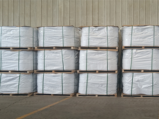
Wires and Cables packaging (1)
Wires and Cables packaging (2)
Wires and Cables packaging (3)
Wires and Cables packaging (4)
Wires and Cables packaging (5)
Wires and Cables packaging (6)
Wires and Cables packaging (7)
Wires and Cables packaging (8)
Related Products
2Y-high-voltage-power-cable.webp)
A2XS(FL)2Y MDPE High Voltage 26/45 (52)kV Power Cable
The A2XS(FL)2Y MDPE High Voltage Power Cable is a single-core aluminum conductor cable with XLPE insulation and an MDPE sheath, rated 26/45 (52) kV. Designed for reliable medium-voltage power transmission, it meets IEC 60840 standards, providing excellent electrical performance, mechanical protection, and environmental resistance. Its construction includes an aluminum conductor, semi-conductive conductor screen, XLPE insulation, semi-conductive insulation screen, semi-conductive water swelling tape, copper wire metallic screen, longitudinal aluminum tape with PE copolymer coating, and an MDPE sheath. Water-blocking tape prevents water propagation inside the cable, ensuring dependable operation in power stations, industrial plants, and distribution networks. Suitable for underground, underwater, indoor, outdoor, and duct installations, this cable is ideal for distribution networks, generation unit connections, and industrial processes.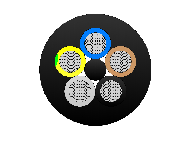
Type 409 Flexible Copper Screened Mining Cable With Central Pilot
The Type 409 Flexible Copper Screened Mining Cable with Central Pilot is a heavy-duty flexible cable engineered for reliable and safe underground mining operations. It features finely stranded tinned copper conductors (class 5) for excellent flexibility and corrosion resistance, EPR (ethylene propylene rubber) insulation for superior dielectric strength and 90°C continuous thermal rating, an overall tinned copper braid screen providing effective EMI protection and grounding, a central pilot core for earth continuity monitoring, safety interlocks, and fault detection, and an extra-heavy-duty flame-retardant rubber outer sheath resistant to oil, abrasion, tearing, crushing, impact, and chemicals. Compliant with AS/NZS 2802 and mining safety standards, it supports high tensile loads, frequent reeling/drag, tight bending radii, and reliable performance in wet, dusty, and hazardous mine conditions. The Type 409 is ideal for power supply to continuous miners, shuttle cars, longwall equipment, drills, and other mobile machinery in coal and metalliferous mines, ensuring enhanced safety through pilot core monitoring and maximum durability.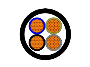
NA2XY-J/O Aluminium XLPE PVC-0.6/1kV Cable
NA2XY-J/O Aluminium XLPE PVC-0.6/1kV Cable is a low-voltage power cable featuring aluminum conductors, XLPE (cross-linked polyethylene) insulation, and a PVC (polyvinyl chloride) outer sheath. It is manufactured in accordance with IEC60502-1 standards and is rated for 0.6/1kV. This cable is a cost-effective alternative to copper conductor cables, offering good electrical and mechanical performance for fixed power distribution systems. Flame-retardant and environmentally robust, the Cable supports industrial, commercial, and residential projects with reliable, long-lasting power transmission.
15kV Copper Conductor URD Cable - MV Underground Distribution Cable
The 15kV Copper Conductor URD Cable is a premium medium-voltage underground distribution cable designed for high-reliability primary and secondary power delivery. It features a stranded high-conductivity copper conductor, extruded semi-conducting shields, tree-retardant TR-XLPE or EPR insulation, and a full copper concentric neutral, all protected by a tough sunlight-resistant LLDPE jacket. This construction provides superior electrical performance, excellent moisture and treeing resistance, and strong mechanical protection suitable for direct burial or duct installations. The high-conductivity copper conductor ensures lower losses and higher ampacity. Manufactured to ICEA S-94-649 and AEIC CS8 standards, the 15kV Copper Conductor URD Cable undergoes rigorous quality testing from raw materials to finished product, ensuring long-term reliability and safety in demanding underground environments.
Single Core Medium Voltage Power Cable to IEC 60502
The Single Core Medium Voltage Power Cable to IEC 60502 is designed for efficient and reliable power transmission in medium voltage electrical networks. Manufactured with high-purity copper or aluminum conductors, this cable ensures low electrical losses and stable current flow. The insulation system, typically based on XLPE, provides excellent dielectric strength, thermal stability, and resistance to electrical stress. Single core construction allows flexible system design and efficient heat dissipation, making the cable suitable for substations, power plants, and industrial installations. The cable is engineered to withstand mechanical loads and operational stresses encountered in medium voltage applications. Compliance with IEC 60502 ensures the cable meets international requirements for safety, electrical performance, and durability. This medium voltage power cable is a dependable solution for modern power distribution systems requiring long service life and consistent performance.
6 Gauge Galvanized Steel Conductor Wire
The 6 Gauge Galvanized Steel Conductor Wire is a premium high-strength bare steel wire designed for overhead power line applications. Manufactured with heavy hot-dip zinc coating, this 6 AWG galvanized conductor provides exceptional corrosion resistance and long service life in harsh outdoor environments. It offers high tensile strength and reliable mechanical performance, making it ideal for use as overhead ground wire (static wire), guy wire, or messenger wire. Compliant with ASTM A475 and related standards, the 6 Gauge Galvanized Steel Conductor Wire undergoes rigorous testing from raw materials to finished product to ensure consistent quality, uniform zinc adhesion, and superior breaking strength. Its durable construction minimizes maintenance while delivering dependable protection and support for transmission and distribution lines.FAQ From Customers
-
What are the advantages of power cables and overhead lines?(1) Reliable operation, because it is installed in a hidden place such as underground, it is less damaged by external forces, has less chance of failure, and the power supply is safe, and it will not cause harm to people; (2) The maintenance workload is small and frequent inspections are not required; (3) No need to erect towers; (4) Help improve power factor.
-
Which aspects should be considered when choosing the cross section of a power cable?(1) The long-term allowable working current of the cable; (2) Thermal stability once short circuited; (3) The voltage drop on the line cannot exceed the allowable working range.
-
What are the measures for cable fire prevention?(1) Use flame-retardant cables; (2) Use fireproof cable tray; (3) Use fireproof paint; (4) Fire partition walls and fire baffles are installed at cable tunnels, mezzanine exits, etc.; (5) Overhead cables should avoid oil pipelines and explosion-proof doors, otherwise local pipes or heat insulation and fire prevention measures should be taken.
-
What should be paid attention to during the transportation and handling of cables?(1) During transportation, loading and unloading, cables and cable reels should not be damaged. It is strictly forbidden to push the cable reels directly from the vehicle. Generally, cables should not be transported and stored flat. (2) Before transporting or rolling the cable reel, ensure that the cable reel is firm, the cable is wound tightly, the oil pipe between the oil-filled cable and the pressure oil tank should be fixed without damage, the pressure oil tank should be firm, and the pressure indication should meet the requirements.
-
What inspections should be carried out for the acceptance of cable lines?(1) The cable specifications should meet the regulations, the arrangement should be neat, no damage, and the signs should be complete, correct and clear; (2) The fixed bending radius of the cable, the related distance and the wiring of the metal sheath of the single-core power cable should meet the requirements; (3) The cable terminal and the middle head should not leak oil, and the installation should be firm. The oil pressure of the oil-filled cable and the meter setting should meet the requirements; (4) Good grounding; (5) The color of the cable terminal is correct, and the metal parts such as the bracket are completely painted; (6) There should be no debris in the cable trench, tunnel, and bridge, and the cover should be complete.
Welcome your inquiry
Honesty, Integrity, Frugality, Activeness and Passion