
ALL ALUMINUM CONDUCTORS(AAC)
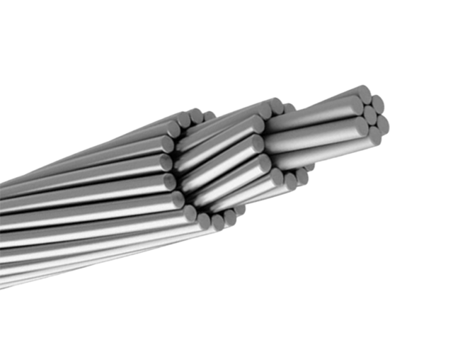
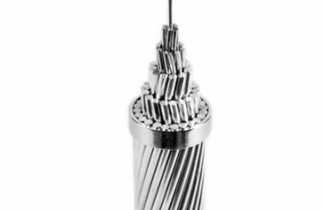
All Aluminum Conductors (AAC) are essential for overhead power transmission and distribution, constructed from concentrically stranded hard-drawn 1350 aluminum wires. Known for their superior electrical conductivity—up to 61.2% IACS—these conductors minimize energy losses, making them cost-effective for urban and rural grids. Lighter than steel-reinforced options, AAC simplifies installation and reduces structural demands on poles and towers. Their excellent corrosion resistance suits moderate environments, though they exhibit higher sag in long spans compared to alloys. Compliant with standards like ASTM B231 and IEC 60889, AAC is available in various sizes, from small distribution lines to higher voltage applications. The stranded design enhances flexibility and durability against wind and ice loads. Ideal for primary and secondary overhead lines, AAC supports efficient power delivery with minimal maintenance. By optimizing conductivity and weight, these conductors contribute to sustainable energy infrastructure, reducing operational costs and enhancing reliability in standard utility setups. Their recyclability aligns with eco-friendly practices in modern electrical networks.
Construction
Technical Specifications
Quality Control
Application
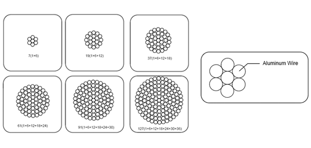
Construction
All Aluminium Conductors
Application
AAC is mainly used in urban areas, where spacing is short and supports are close together. All-aluminium conductors consist of one or more strands of aluminium wire, depending on the intended use. AAC is also widely used in coastal regions due to its high corrosion resistance.
Description
Aluminium Conductors (AAC) are made of Hard-Drawn aluminum wires.
Standard
IEC 61089, DIN 48201-5, AS 1531, BS 215-1, BS EN 50182, ASTM B 231/B 231/M. Gost 83980.
Technical Specifications
ALL ALUMINUM CONDUCTORS(AAC)
ASTM B 231/B 231M
IEC 61089
DIN 48201-5
BS 215-1
BS EN 50182
GOST 839-80
GB/T 1179
| Code Name | Nominal Area |
No./Nominal diameter of wires |
Approximate Overall Diameter |
Approximate Weight |
Nominal Breaking Load |
Nominal DC Resistance at 20°C |
|
| AWG or MCM | mm² | No./mm | mm | kg/km | KN | ohm/km | |
| Peachbell | 6 | 13.3 | 7/1.56 | 4.68 | 36.6 | 2.5 | 2.1477 |
| Rose | 4 | 21.1 | 7/1.96 | 5.88 | 58.2 | 3.9 | 1.3606 |
| Iris | 2 | 33.6 | 7/2.47 | 7.41 | 92.6 | 6.0 | 0.8567 |
| Pansy | 1 | 42.4 | 7/2.78 | 8.34 | 116.6 | 7.3 | 0.6763 |
| Poppy | 1/0.0 | 53.5 | 7/3.12 | 9.36 | 147.2 | 8.8 | 0.5369 |
| Aster | 2/0.0 | 67.4 | 7/3.50 | 10.50 | 185.7 | 11.1 | 0.4267 |
| Phlox | 3/0.0 | 85.0 | 7/3.93 | 11.79 | 233.9 | 13.5 | 0.3384 |
| Oxlip | 4/0.0 | 107.2 | 7/4.42 | 13.26 | 295.2 | 17.0 | 0.2675 |
| Valerian | 250.0 | 126.7 | 19/2.91 | 14.55 | 348.6 | 20.7 | 0.2274 |
| Sneezewort | 250.0 | 126.7 | 7/4.80 | 14.40 | 348.8 | 20.1 | 0.2269 |
| Laurel | 266.8 | 135.2 | 19/3.01 | 15.05 | 372.2 | 22.1 | 0.2125 |
| Daisy | 266.8 | 135.2 | 7/4.96 | 14.88 | 372.3 | 21.4 | 0.2125 |
| Peony | 300.0 | 152.0 | 19/3.19 | 15.95 | 418.3 | 24.3 | 0.1892 |
| Tulip | 336.4 | 170.5 | 19/3.38 | 16.90 | 469.5 | 27.3 | 0.1686 |
| Daffodil | 350.0 | 177.3 | 19/3.45 | 17.25 | 487.9 | 28.4 | 0.1618 |
| Canna | 397.5 | 201.4 | 19/3.67 | 18.35 | 554.9 | 31.6 | 0.1430 |
| Goldentuft | 450.0 | 228.0 | 19/3.91 | 19.55 | 627.6 | 35.0 | 0.1260 |
| Syringa | 477.0 | 241.7 | 37/2.88 | 20.16 | 664.8 | 38.6 | 0.1192 |
| Cosmos | 477.0 | 241.7 | 19/4.02 | 20.10 | 664.8 | 37.0 | 0.1192 |
| Hyacinth | 500.0 | 253.3 | 37/2.95 | 20.65 | 696.8 | 40.5 | 0.1136 |
| Zinnia | 500.0 | 253.3 | 19/4.12 | 20.60 | 697.1 | 38.9 | 0.1134 |
| Dahlia | 556.5 | 282.0 | 19/4.35 | 21.75 | 775.8 | 43.3 | 0.1018 |
| Mistletoe | 556.5 | 282.0 | 37/3.12 | 21.84 | 775.7 | 44.3 | 0.1016 |
| Meadowsweet | 600.0 | 304.0 | 37/3.23 | 22.61 | 836.3 | 47.5 | 0.0948 |
| Orchid | 636.0 | 322.3 | 37/3.33 | 23.31 | 886.9 | 50.4 | 0.0892 |
| Heuchera | 650.0 | 329.4 | 37/3.37 | 23.59 | 907.4 | 51.7 | 0.0871 |
| Flag | 700.0 | 354.7 | 61/2.72 | 24.48 | 975.8 | 57.1 | 0.0811 |
| Varbena | 700.0 | 354.7 | 37/3.49 | 24.43 | 975.7 | 55.4 | 0.0812 |
| Nasturtium | 715.5 | 362.6 | 61/2.75 | 24.75 | 998.5 | 58.4 | 0.0793 |
| Violet | 715.5 | 362.6 | 37/3.53 | 24.71 | 998.5 | 56.7 | 0.0794 |
| Cattail | 750.0 | 380.0 | 61/2.82 | 25.38 | 1046.0 | 60.3 | 0.0754 |
| Petunia | 750.0 | 380.0 | 37/3.62 | 25.34 | 1046.0 | 58.6 | 0.0755 |
| Lilac | 795.0 | 402.8 | 61/2.90 | 26.10 | 1110.0 | 63.8 | 0.0713 |
| Arbutus | 795.0 | 402.8 | 37/3.72 | 26.04 | 1109.0 | 61.8 | 0.0715 |
| Snapdragon | 900.0 | 456.0 | 61/3.09 | 27.81 | 1256.0 | 70.8 | 0.0628 |
| Cockscomb | 900.0 | 456.0 | 37/3.96 | 27.72 | 1256.0 | 68.4 | 0.0631 |
| Goldenrod | 954.0 | 483.4 | 61/3.18 | 28.62 | 1331.0 | 75.0 | 0.0593 |
| Magnolia | 954.0 | 483.4 | 37/4.08 | 28.56 | 1331.0 | 72.6 | 0.0594 |
| Camellia | 1000.0 | 506.7 | 61/3.25 | 29.25 | 1394.0 | 78.3 | 0.0568 |
| Hawkweed | 1000.0 | 506.7 | 37/4.18 | 29.26 | 1395.0 | 76.2 | 0.0566 |
| Larkspur | 1033.5 | 523.7 | 61/3.31 | 29.79 | 1442.0 | 81.3 | 0.0547 |
| Bluebell | 1033.5 | 523.7 | 37/4.25 | 29.75 | 1441.0 | 78.8 | 0.0547 |
| Marigold | 1113.0 | 564.0 | 61/3.43 | 30.87 | 1553.0 | 87.3 | 0.0510 |
| Hawthorn | 1192.5 | 604.2 | 61/3.55 | 31.95 | 1662.0 | 93.5 | 0.0476 |
| Narsissus | 1272.0 | 644.5 | 61/3.67 | 33.03 | 1774.0 | 98.1 | 0.0445 |
| Columbine | 1351.0 | 694.8 | 61/3.78 | 34.02 | 1884.0 | 104.0 | 0.0420 |
| Carnation | 1431.0 | 725.1 | 61/3.89 | 35.01 | 1997.0 | 108.0 | 0.0396 |
| Gladiolus | 1510.5 | 765.4 | 61/4.00 | 36.00 | 2108.0 | 114.0 | 0.0375 |
| Coreopsis | 1590.0 | 805.7 | 61/4.10 | 36.90 | 2216.0 | 120.0 | 0.0357 |
| Jassamine | 1750.0 | 886.7 | 61/4.30 | 38.70 | 2442.0 | 132.0 | 0.0324 |
| Cowslip | 2000.0 | 1013.0 | 91/3.77 | 41.47 | 2787.0 | 153.0 | 0.0286 |
| Sagebrush | 2250.0 | 1140.0 | 91/3.99 | 43.89 | 3166.0 | 167.0 | 0.0255 |
| Lupine | 2500.0 | 1267.0 | 91/4.21 | 46.31 | 3519.0 | 186.0 | 0.0229 |
| Bitterrot | 2750.0 | 1393.0 | 91/4.42 | 48.62 | 3872.0 | 205.0 | 0.0208 |
| Trillium | 3000.0 | 1520.0 | 127/3.90 | 50.70 | 4226.0 | 223.0 | 0.0193 |
| Bluebonnet | 3500.0 | 1773.0 | 127/4.22 | 54.86 | 4977.0 | 261.0 | 0.0165 |
| Code Name | Nominal Area |
No./Nominal diameter of wires |
Approximate Overall Diameter |
Approximate Weight |
Nominal Breaking Load |
Nominal DC Resistance at 20°C |
| mm² | No./mm | mm | kg/km | KN | ohm/km | |
| 10 | 10.0 | 7/1.35 | 4.05 | 27.4 | 2.0 | 2.8633 |
| 16 | 16.0 | 7/1.71 | 5.13 | 43.8 | 3.0 | 1.7896 |
| 25 | 25.0 | 7/2.13 | 6.39 | 68.4 | 4.5 | 1.1453 |
| 40 | 40.0 | 7/2.70 | 8.10 | 109.4 | 6.8 | 0.7158 |
| 63 | 63.0 | 7/3.39 | 10.17 | 172.3 | 10.4 | 0.4545 |
| 100 | 100.0 | 19/2.59 | 12.95 | 274.8 | 17.0 | 0.2877 |
| 125 | 125.0 | 19/2.89 | 14.45 | 343.6 | 21.3 | 0.2302 |
| 160 | 160.0 | 19/3.27 | 16.35 | 439.8 | 26.4 | 0.1798 |
| 200 | 200.0 | 19/3.66 | 18.30 | 549.7 | 32.0 | 0.1439 |
| 250 | 250.0 | 19/4.09 | 20.45 | 687.1 | 40.0 | 0.1151 |
| 315 | 315.0 | 37/3.29 | 23.03 | 867.9 | 52.0 | 0.0916 |
| 400 | 400.0 | 37/3.71 | 25.97 | 1102.0 | 64.0 | 0.0721 |
| 450 | 450.0 | 37/3.94 | 27.58 | 1239.8 | 72.0 | 0.0641 |
| 500 | 500.0 | 37/4.15 | 29.05 | 1377.6 | 80.0 | 0.0577 |
| 560 | 560.0 | 37/4.39 | 30.73 | 1542.9 | 89.6 | 0.0515 |
| 630 | 630.0 | 61/3.63 | 32.67 | 1738.3 | 100.8 | 0.0458 |
| 710 | 710.0 | 61/3.85 | 34.65 | 1959.1 | 113.6 | 0.0407 |
| 800 | 800.0 | 61/4.09 | 36.81 | 2207.4 | 128.0 | 0.0361 |
| 900 | 900.0 | 61/4.33 | 38.97 | 2483.3 | 144.0 | 0.0321 |
| 1000 | 1000.0 | 61/4.57 | 41.13 | 2759.2 | 160.0 | 0.0289 |
| 1120 | 1120.0 | 91/3.96 | 43.56 | 3093.5 | 179.2 | 0.0258 |
| 1250 | 1250.0 | 91/4.18 | 45.98 | 3452.6 | 200.0 | 0.0231 |
| 1400 | 1400.0 | 91/4.43 | 48.73 | 3866.9 | 224.0 | 0.0207 |
| 1500 | 1500.0 | 91/4.58 | 50.38 | 4143.1 | 240.0 | 0.0193 |
| Area | No./Nominal diameter of wires |
Approximate Overall Diameter |
Approximate Weight |
Nominal Breaking Load |
Nominal DC Resistance at 20°C |
|
| Nominal | Actual | |||||
| mm² | mm² | No./mm | mm | kg/km | KN | ohm/km |
| 16.0 | 15.9 | 7/1.70 | 5.10 | 43.0 | 2.8 | 1.8022 |
| 25.0 | 24.3 | 7/2.10 | 6.30 | 66.0 | 4.2 | 1.1810 |
| 35.0 | 34.4 | 7/2.50 | 7.50 | 94.0 | 5.8 | 0.8333 |
| 50.0 | 49.5 | 7/3.00 | 9.00 | 135.0 | 7.9 | 0.5787 |
| 50.0 | 48.4 | 19/1.80 | 9.00 | 133.0 | 8.5 | 0.5951 |
| 70.0 | 65.8 | 19/2.10 | 10.50 | 181.0 | 11.3 | 0.4372 |
| 95.0 | 93.3 | 19/2.50 | 12.50 | 256.0 | 15.7 | 0.3085 |
| 120.0 | 117.0 | 19/2.80 | 14.00 | 322.0 | 18.8 | 0.2459 |
| 150.0 | 147.1 | 37/2.25 | 15.80 | 406.0 | 25.3 | 0.1960 |
| 185.0 | 181.6 | 37/2.50 | 17.50 | 500.0 | 30.5 | 0.1588 |
| 240.0 | 242.5 | 61/2.25 | 20.30 | 670.0 | 39.5 | 0.1191 |
| 300.0 | 299.4 | 61/2.50 | 22.50 | 827.0 | 47.7 | 0.0965 |
| 400.0 | 400.1 | 61/2.89 | 26.00 | 1104.0 | 60.9 | 0.0722 |
| 500.0 | 499.8 | 61/3.23 | 29.10 | 1379.0 | 74.7 | 0.0578 |
| 625.0 | 626.2 | 91/2.96 | 32.60 | 1732.0 | 95.3 | 0.0462 |
| 800.0 | 802.1 | 91/3.35 | 36.90 | 2218.0 | 118.4 | 0.0360 |
| 1000.0 | 999.7 | 91/3.74 | 41.10 | 2767.0 | 145.8 | 0.0289 |
| Code Name | Nominal Area |
No./Nominal diameter of wires |
Approximate Overall Diameter |
Total Area | Approximate Weight |
Nominal Breaking Load |
Nominal DC Resistance at 20°C |
| mm² | No./mm | mm | mm² | kg/km | KN | ohm/km | |
| Midge | 22.0 | 7/2.06 | 6.18 | 23.3 | 64.0 | 4.0 | 1.2270 |
| Ant | 50.0 | 7/3.10 | 9.30 | 52.8 | 145.0 | 8.3 | 0.5419 |
| Fly | 60.0 | 7/3.40 | 10.20 | 63.6 | 174.0 | 9.9 | 0.4505 |
| Wasp | 100.0 | 7/4.39 | 13.17 | 106.0 | 290.0 | 16.0 | 0.2702 |
| Hornet | 150.0 | 19/3.25 | 16.25 | 157.6 | 434.0 | 25.7 | 0.1825 |
| Chafer | 200.0 | 19/3.78 | 18.90 | 213.2 | 587.0 | 32.4 | 0.1349 |
| Cockroach | 250.0 | 19/4.22 | 21.10 | 265.7 | 731.0 | 40.4 | 0.1083 |
| Butterfly | 300.0 | 19/4.65 | 23.25 | 322.7 | 888.0 | 48.8 | 0.0892 |
| Centipede | 400.0 | 37/3.78 | 26.46 | 415.2 | 1145.0 | 63.1 | 0.0694 |
| Code Name | Nominal Area |
No./Nominal diameter of wires |
Approximate Overall Diameter |
Total Area | Approximate Weight |
Nominal Breaking Load |
Nominal DC Resistance at 20°C |
| mm² | No./mm | mm | mm² | kg/km | KN | ohm/km | |
| Gnat | -- | 7/2.21 | 6.63 | 26.9 | 73.0 | 4.8 | 1.0643 |
| Mosquito | -- | 7/2.59 | 7.77 | 36.9 | 101.0 | 6.3 | 0.7749 |
| Ladybird | -- | 7/2.79 | 8.37 | 42.8 | 117.0 | 7.3 | 0.6678 |
| Bluebottle | -- | 7/3.66 | 10.98 | 73.6 | 201.0 | 11.8 | 0.3880 |
| Earwig | -- | 7/3.78 | 11.34 | 78.6 | 215.0 | 12.6 | 0.3638 |
| Grasshopper | -- | 7/3.91 | 11.73 | 84.1 | 230.0 | 13.5 | 0.3400 |
| Clegg | -- | 7/4.17 | 12.51 | 95.6 | 261.0 | 15.3 | 0.2989 |
| Beetle | -- | 19/2.67 | 13.35 | 106.4 | 292.0 | 18.1 | 0.2701 |
| Bee | -- | 7/4.90 | 14.70 | 132 | 361.0 | 21.1 | 0.2165 |
| Caterpillar | -- | 19/3.53 | 17.65 | 185.9 | 511.0 | 29.8 | 0.1546 |
| Spider | -- | 19/3.99 | 19.95 | 237.6 | 653.0 | 38.0 | 0.1210 |
| Moth | -- | 19/5.00 | 25.00 | 373.1 | 1025.0 | 59.7 | 0.0770 |
| Drone | -- | 37/3.58 | 25.06 | 372.4 | 1027.0 | 59.6 | 0.0774 |
| Maybug | -- | 37/4.09 | 28.63 | 486.1 | 1341.0 | 77.8 | 0.0593 |
| Scorpion | -- | 37/4.27 | 29.89 | 529.8 | 1461.0 | 84.8 | 0.0544 |
| Cicada | -- | 37/4.65 | 32.55 | 628.3 | 1733.0 | 100.5 | 0.0459 |
| Nominal Corss-section | Number of Wires | Wire Diameter | Calculated Cross-section | Overall Diameter | D.C. Resistance at 20 | Min. Breaking Load | Conductor Weight |
| mm² | mm | mm² | mm | Ω/km | kg/km | ||
| 10 | 7 | 1,35 | 10,0 | 4,05 | 28,631 | 1950 | 27,4 |
| 16 | 7 | 1,70 | 15,9 | 5,10 | 18,007 | 3021 | 43,0 |
| 25 | 7 | 2,13 | 24,9 | 6,40 | 11,498 | 4500 | 68,0 |
| 35 | 7 | 2,50 | 34,3 | 7,50 | 0,8347 | 5913 | 94,0 |
| 40 | 7 | 2,70 | 40,0 | 8,09 | 0,7157 | 6800 | 109,4 |
| 50 | 7 | 3,00 | 49,5 | 9,00 | 0,5784 | 8198 | 135,0 |
| 63 | 7 | 3,39 | 63,0 | 10,16 | 0,4544 | 10390 | 172,3 |
| 70 | 7 | 3,55 | 69,3 | 10,70 | 0,4131 | 11288 | 189,0 |
| 95 | 7 | 4,10 | 92,4 | 12,30 | 0,3114 | 14784 | 252,0 |
| 100 | 19 | 2,59 | 100,0 | 12,94 | 0,2877 | 17000 | 274,9 |
| 120 | 19 | 2,80 | 117,0 | 14,00 | 0,2459 | 19890 | 321,0 |
| 125 | 19 | 2,89 | 125,0 | 14,47 | 0,2301 | 21250 | 343,6 |
| 150 | 19 | 3,15 | 148,0 | 15,80 | 0,1944 | 24420 | 406,0 |
| 160 | 19 | 3,27 | 160,0 | 16,37 | 0,1798 | 26400 | 439,8 |
| 185 | 19 | 3,50 | 182,8 | 17,50 | 0,1574 | 29832 | 502,0 |
| 200 | 19 | 3,66 | 200,0 | 18,30 | 0,1438 | 32000 | 549,7 |
| 240 | 19 | 4,00 | 238,7 | 20,00 | 0,1205 | 38192 | 655,0 |
| 250 | 19 | 4,09 | 250,0 | 20,47 | 0,1150 | 40000 | 687,1 |
| 300 | 37 | 3,15 | 288,3 | 22,10 | 0,1000 | 47569 | 794,0 |
| 315 | 37 | 3,29 | 315,0 | 23,05 | 0,0915 | 51970 | 867,5 |
| 350 | 37 | 3,45 | 345,8 | 24,20 | 0,0833 | 57057 | 952,0 |
| 400 | 37 | 3,66 | 389,2 | 25,60 | 0,0740 | 63420 | 1072,0 |
| 450 | 37 | 3,90 | 449,1 | 27,30 | 0,0642 | 71856 | 1206,0 |
| 500 | 37 | 4,15 | 500,4 | 29,10 | 0,0576 | 80000 | 1378,0 |
| 550 | 61 | 3,37 | 544,0 | 30,30 | 0,0529 | 89760 | 1500,0 |
| 560 | 37 | 4,39 | 560,0 | 30,73 | 0,0531 | 89600 | 1542,2 |
| 600 | 61 | 3,50 | 586,8 | 31,50 | 0,0491 | 95632 | 1618,0 |
| 630 | 61 | 3,63 | 630,0 | 32,64 | 0,0458 | 100800 | 1738,4 |
| 650 | 61 | 3,66 | 641,7 | 32,90 | 0,0450 | 104575 | 1771,0 |
| 700 | 61 | 3,80 | 691,7 | 34,20 | 0,0417 | 112725 | 1902,0 |
| 710 | 61 | 3,85 | 710,0 | 34,65 | 0,0406 | 113600 | 1959,2 |
| 750 | 61 | 3,95 | 747,4 | 35,60 | 0,0386 | 119584 | 2062,0 |
| Nominal Area |
Total Area | No./Nominal diameter of wires |
Approximate Overall Diameter |
Approximate Weight |
Nominal Breaking Load |
Nominal DC Resistance at 20°C |
| mm² | mm² | No./mm | mm | kg/km | KN | ohm/km |
| 35.0 | 34.4 | 7/2.50 | 7.50 | 94.0 | 6.0 | 0.8333 |
| 50.0 | 49.5 | 7/3.00 | 9.00 | 135.3 | 8.4 | 0.5787 |
| 70.0 | 71.3 | 7/3.60 | 10.80 | 194.9 | 11.4 | 0.4019 |
| 95.0 | 95.1 | 7/4.16 | 12.50 | 260.2 | 15.2 | 0.3010 |
| 120.0 | 121.2 | 19/2.85 | 14.30 | 333.2 | 20.6 | 0.2374 |
| 150.0 | 148.1 | 19/3.15 | 15.80 | 407.0 | 24.4 | 0.1943 |
| 185.0 | 182.8 | 19/3.50 | 17.50 | 502.4 | 30.2 | 0.1574 |
| 210.0 | 209.9 | 193.75 | 18.80 | 576.8 | 33.6 | 0.1371 |
| 240.0 | 238.8 | 19/4.00 | 20.00 | 656.3 | 38.2 | 0.1205 |
| 300.0 | 297.6 | 19/3.20 | 22.40 | 819.8 | 49.1 | 0.0969 |
| 500.0 | 502.9 | 19/4.16 | 29.10 | 1385.5 | 80.5 | 0.0573 |
Quality Control
ALL ALUMINUM CONDUCTORS(AAC)
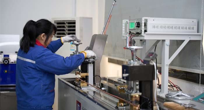
Raw Material Testing
Raw material testing for AAC conductors focuses on aluminum rods to ensure purity and performance. Chemical composition is analyzed via spectrometry, confirming 99.5% minimum aluminum content with low impurities like iron or silicon per ASTM B231. Tensile strength tests pull samples to measure ultimate strength (55-160 MPa) and yield, verifying hardness for drawing. Elongation is assessed by stretching to fracture, targeting 1.5-4% for ductility. Conductivity testing uses resistivity meters to achieve 61% IACS minimum. Density checks around 2.70 g/cm³ detect anomalies. Visual and microscopic inspections identify surface defects or inclusions. Hardness via Rockwell tests confirms temper. Batches are traced with documentation, rejecting non-compliant materials to prevent issues in final products.
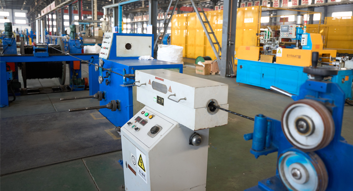
Process Inspection
Process inspection in AAC manufacturing ensures quality at each step. Wire drawing is monitored for diameter precision using micrometers, maintaining tolerances to avoid stranding flaws. Surface quality checks with scanners detect scratches or oxidation. Annealing processes are verified for temperature control to optimize conductivity. Stranding inspections measure lay length and compactness per IEC 60889, ensuring concentricity. Interim conductivity tests identify resistance variations. Sampling includes tensile and bend tests on wires. Cleanliness audits prevent contamination. Digital logging enables traceability and corrective actions for deviations, enhancing uniformity for overhead use.
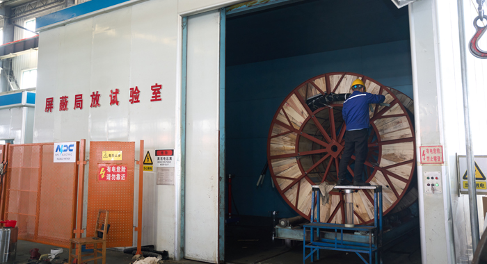
Finished Product
Finished AAC testing validates performance for deployment. Tensile tests on samples measure breaking load and elongation, exceeding ASTM B231 specs. Conductivity is confirmed with bridges for low resistance. Dimensional checks verify diameter and strand count. Surface inspections ensure smoothness and a defect-free finish. Sag and creep tests predict behavior under load. Fatigue simulations assess vibration resistance. Packaging is inspected for protection. Certificates confirm compliance, minimizing field risks in power lines.
Application
AAC conductors are perfect for short-span overhead distribution in urban areas, residential grids, and mild climates. They support efficient power delivery in secondary lines, substations, and renewable integrations like solar arrays, where high conductivity is key.


Technical Advantages
● 30+ years of manufacturing experience
● ISO and UL certified production
● Customized cable and transformer solutions


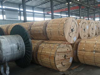
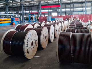
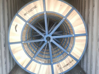
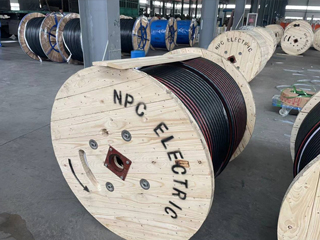
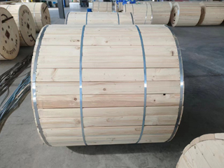
Product Packaging
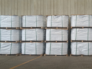
Wires and Cables packaging (1)
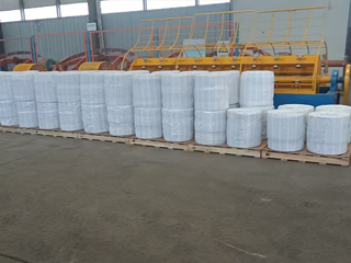
Wires and Cables packaging (2)
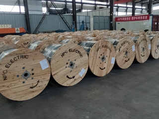
Wires and Cables packaging (3)
Wires and Cables packaging (4)
Wires and Cables packaging (5)
Wires and Cables packaging (6)
Wires and Cables packaging (7)
Wires and Cables packaging (8)
Related Products
715.5 MCM Violet AAC Cable
The 715.5 MCM Violet AAC Cable is a high-performance All Aluminum Conductor designed for demanding overhead power transmission and distribution lines. Manufactured with 37 strands of premium 1350-H19 aluminum wire in a concentric lay configuration, this bare conductor provides excellent electrical conductivity with a low DC resistance of 0.024 ohms per 1000 ft at 20°C. Featuring an overall diameter of 0.974 inches and a rated breaking strength of 12,800 lbs, the Violet AAC delivers a robust ampacity of 823 amps while weighing only 671.7 lbs per 1000 ft. Its optimized strength-to-weight ratio minimizes sag and structural loading. Fully compliant with ASTM B-230 and B-231 standards, the 715.5 MCM Violet AAC Cable offers outstanding corrosion resistance for long-term durability in harsh outdoor environments, making it the preferred choice for utility networks requiring cost-effective, high-reliability bare aluminum conductors.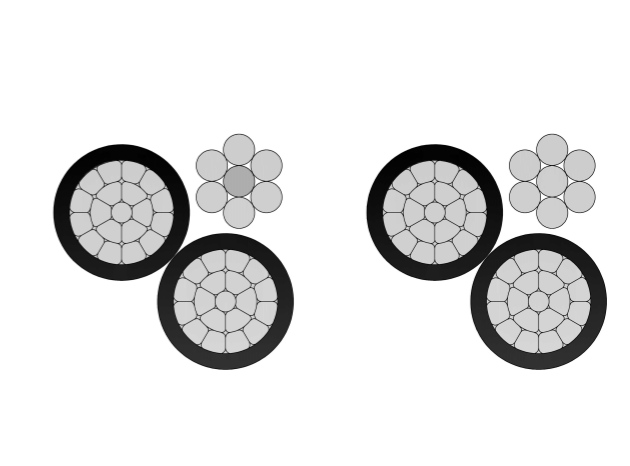
2/0 Trophon Aluminum Conductor Triplex Overhead Service Drop Cable
The 2/0 Trophon Aluminum Conductor Triplex Overhead Service Drop Cable delivers superior performance for overhead power distribution. Engineered with high-quality 1350-H19 aluminum conductors, black cross-linked polyethylene (XLPE) insulation, and a bare ACSR neutral messenger, this triplex cable ensures excellent conductivity, weather resistance, and mechanical strength. Rated for 600V phase-to-phase at up to 90°C conductor temperature (XLP), it offers approx. 230A ampacity, making it ideal for residential and light commercial service entrances. Compliant with ASTM B-230, B-231, B-232, and ICEA S-76-474 standards, the cable withstands harsh outdoor conditions while maintaining flexibility and reliability.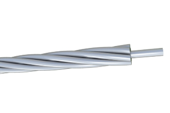
12 Gauge Galvanized Steel Conductor Wire
The 12 Gauge Galvanized Steel Conductor Wire is engineered for demanding utility applications, delivering reliable high-strength performance with outstanding corrosion resistance. Produced with heavy hot-dip galvanizing, this 12 AWG wire features a uniform zinc coating that effectively protects against rust in challenging environments. It performs exceptionally well as overhead ground wire, static wire, or guy wire for pole guying in power transmission and distribution systems. Meeting ASTM A475 requirements, the 12 Gauge Galvanized Steel Conductor Wire provides excellent tensile strength and long service life with minimal maintenance. Rigorous quality testing throughout production ensures consistent mechanical properties and coating integrity, making it a cost-effective and dependable solution for shielding and structural support in overhead lines.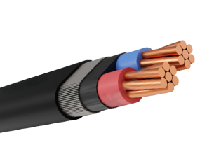
Airdac SNE & CNE Concentric Cable
The Airdac SNE & CNE Concentric Cable is a robust low-voltage aerial service connection cable designed for reliable house service from the distribution network to the consumer meter. It features a circular stranded hard-drawn copper phase conductor insulated with XLPE, surrounded by concentrically arranged neutral and earth conductors, and protected by a black polyethylene sheath. The SNE version provides separate neutral and earth conductors, while the CNE version combines them for simplified earthing. With a nylon ripcord for easy stripping and UV-stabilized materials, this cable offers excellent mechanical strength, electrical performance, and long-term durability. Manufactured to SANS 1507-6 and related standards, the Airdac SNE & CNE Concentric Cable undergoes rigorous quality testing from raw materials to finished product, ensuring safe, tamper-resistant, and vandal-proof performance in overhead or underground installations.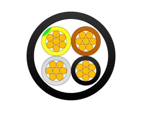
GYTS Fiber Optic Cable
The GYTS Fiber Optic Cable is engineered for outdoor communication applications requiring reliable optical transmission and enhanced mechanical protection. Featuring a stranded loose tube design, central strength member, water-blocking filling compound, aluminum moisture barrier, corrugated steel tape armor, and PE outer jacket, the cable provides outstanding performance in challenging environments. The gel-filled loose tubes protect optical fibers from moisture ingress and mechanical stress while maintaining stable transmission characteristics. The APL moisture barrier prevents water penetration, and the PSP steel tape armor enhances crush resistance, impact protection, and rodent resistance. The UV-resistant PE sheath ensures excellent resistance to weathering, chemicals, and environmental aging. Manufactured according to IEC 60794 and ITU-T standards, the GYTS Fiber Optic Cable is widely used in telecommunications networks, utility communication systems, broadband deployment projects, and industrial communication infrastructure. The cable offers a cost-effective and highly durable solution for outdoor fiber optic network installations.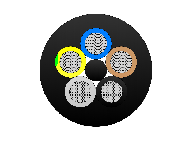
Type 245 Flexible Rubber Mining Cable
The Type 245 Flexible Rubber Mining Cable is an extra-heavy-duty flexible cable purpose-built for the most severe high-voltage underground mining environments. It features finely stranded tinned copper conductors (class 5) for exceptional flexibility and corrosion resistance, EPR (ethylene propylene rubber) insulation for outstanding dielectric strength, thermal stability (90°C continuous rating), and resistance to moisture/heat, an overall tinned copper braid screen providing superior EMI protection and grounding, and an extra-heavy-duty flame-retardant rubber outer sheath engineered to endure extreme abrasion, crushing, impact, cutting, tearing, oils, chemicals, and repeated high-tension reeling/drag. Compliant with AS/NZS 2802 and rigorous mining safety standards, it supports very high tensile loads, frequent flexing, tight bending radii, and reliable operation in wet, dusty, and hazardous mine conditions. The Type 245 is specifically suited for high-power trailing applications in coal and metalliferous mines, powering longwall shearers, continuous miners, face conveyors, shuttle cars, and other critical high-capacity mobile equipment, delivering maximum safety, durability, and uptime.FAQ From Customers
-
What are the advantages of power cables and overhead lines?(1) Reliable operation, because it is installed in a hidden place such as underground, it is less damaged by external forces, has less chance of failure, and the power supply is safe, and it will not cause harm to people; (2) The maintenance workload is small and frequent inspections are not required; (3) No need to erect towers; (4) Help improve power factor.
-
Which aspects should be considered when choosing the cross section of a power cable?(1) The long-term allowable working current of the cable; (2) Thermal stability once short circuited; (3) The voltage drop on the line cannot exceed the allowable working range.
-
What are the measures for cable fire prevention?(1) Use flame-retardant cables; (2) Use fireproof cable tray; (3) Use fireproof paint; (4) Fire partition walls and fire baffles are installed at cable tunnels, mezzanine exits, etc.; (5) Overhead cables should avoid oil pipelines and explosion-proof doors, otherwise local pipes or heat insulation and fire prevention measures should be taken.
-
What should be paid attention to during the transportation and handling of cables?(1) During transportation, loading and unloading, cables and cable reels should not be damaged. It is strictly forbidden to push the cable reels directly from the vehicle. Generally, cables should not be transported and stored flat. (2) Before transporting or rolling the cable reel, ensure that the cable reel is firm, the cable is wound tightly, the oil pipe between the oil-filled cable and the pressure oil tank should be fixed without damage, the pressure oil tank should be firm, and the pressure indication should meet the requirements.
-
What inspections should be carried out for the acceptance of cable lines?(1) The cable specifications should meet the regulations, the arrangement should be neat, no damage, and the signs should be complete, correct and clear; (2) The fixed bending radius of the cable, the related distance and the wiring of the metal sheath of the single-core power cable should meet the requirements; (3) The cable terminal and the middle head should not leak oil, and the installation should be firm. The oil pressure of the oil-filled cable and the meter setting should meet the requirements; (4) Good grounding; (5) The color of the cable terminal is correct, and the metal parts such as the bracket are completely painted; (6) There should be no debris in the cable trench, tunnel, and bridge, and the cover should be complete.
Welcome your inquiry
Honesty, Integrity, Frugality, Activeness and Passion