


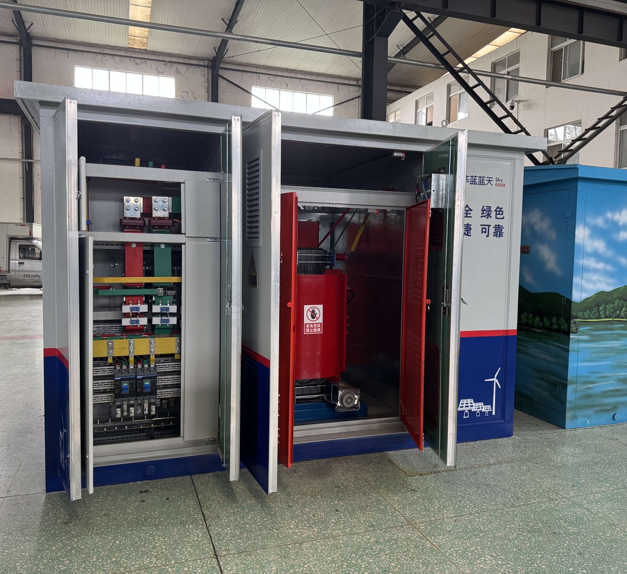
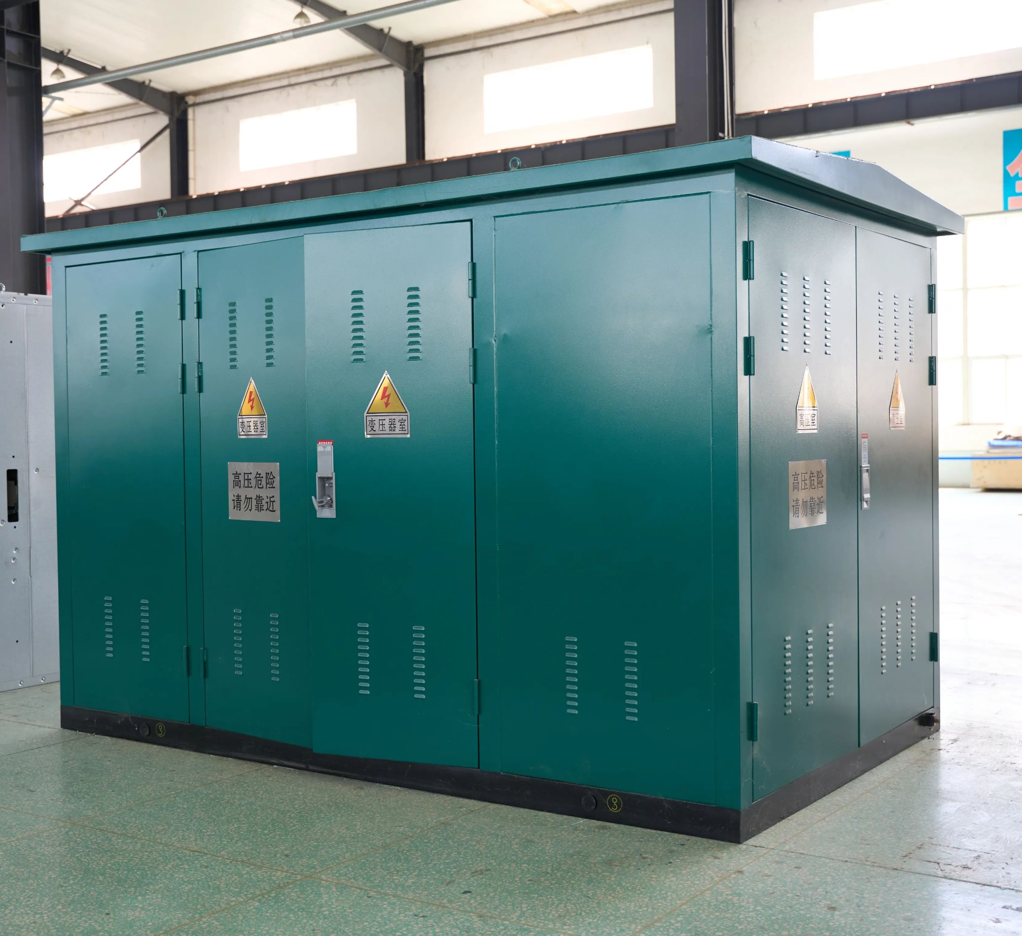
2000kVA 35kV Wind Turbine Step-Up Transformer for Onshore Wind Farms
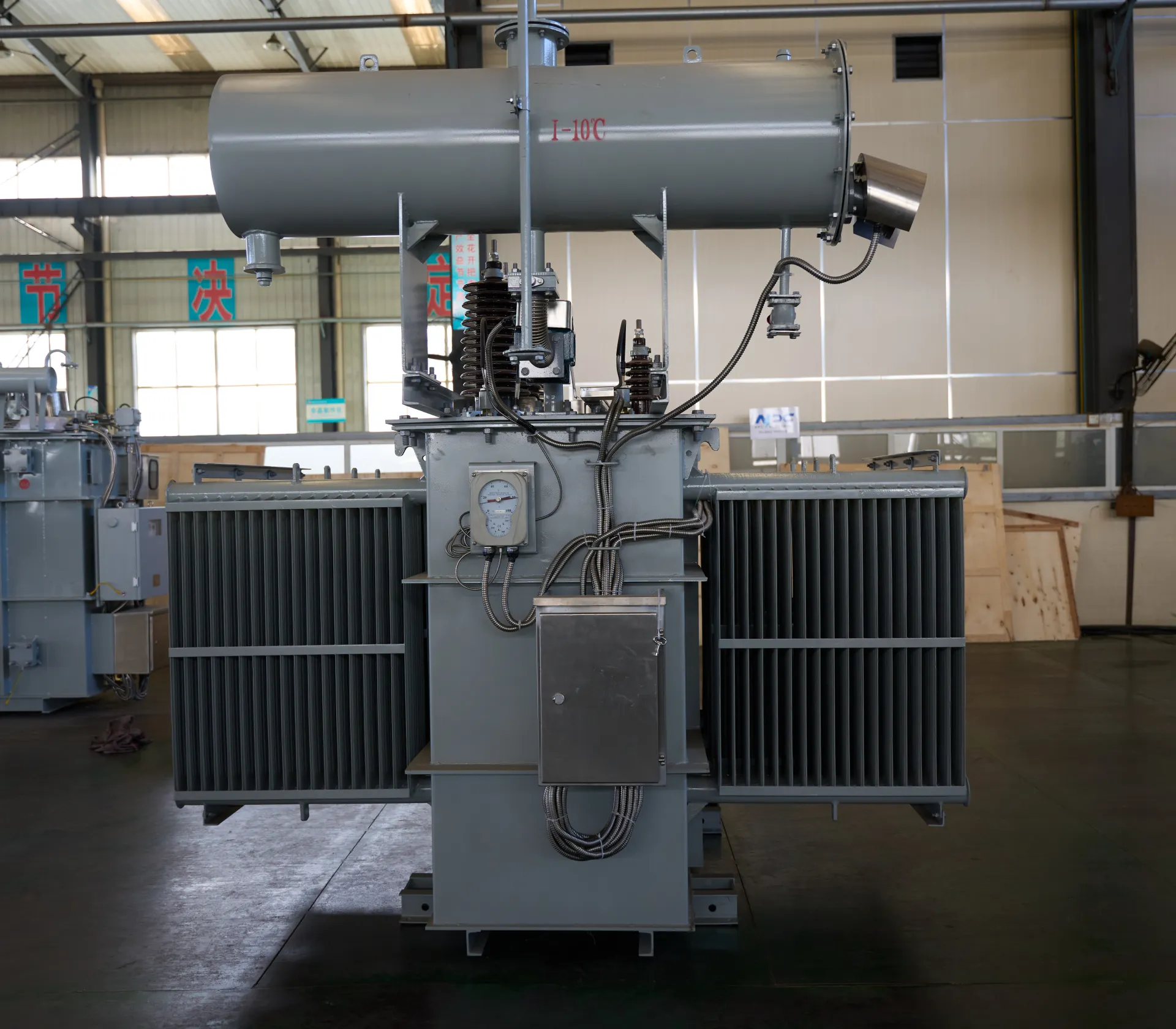
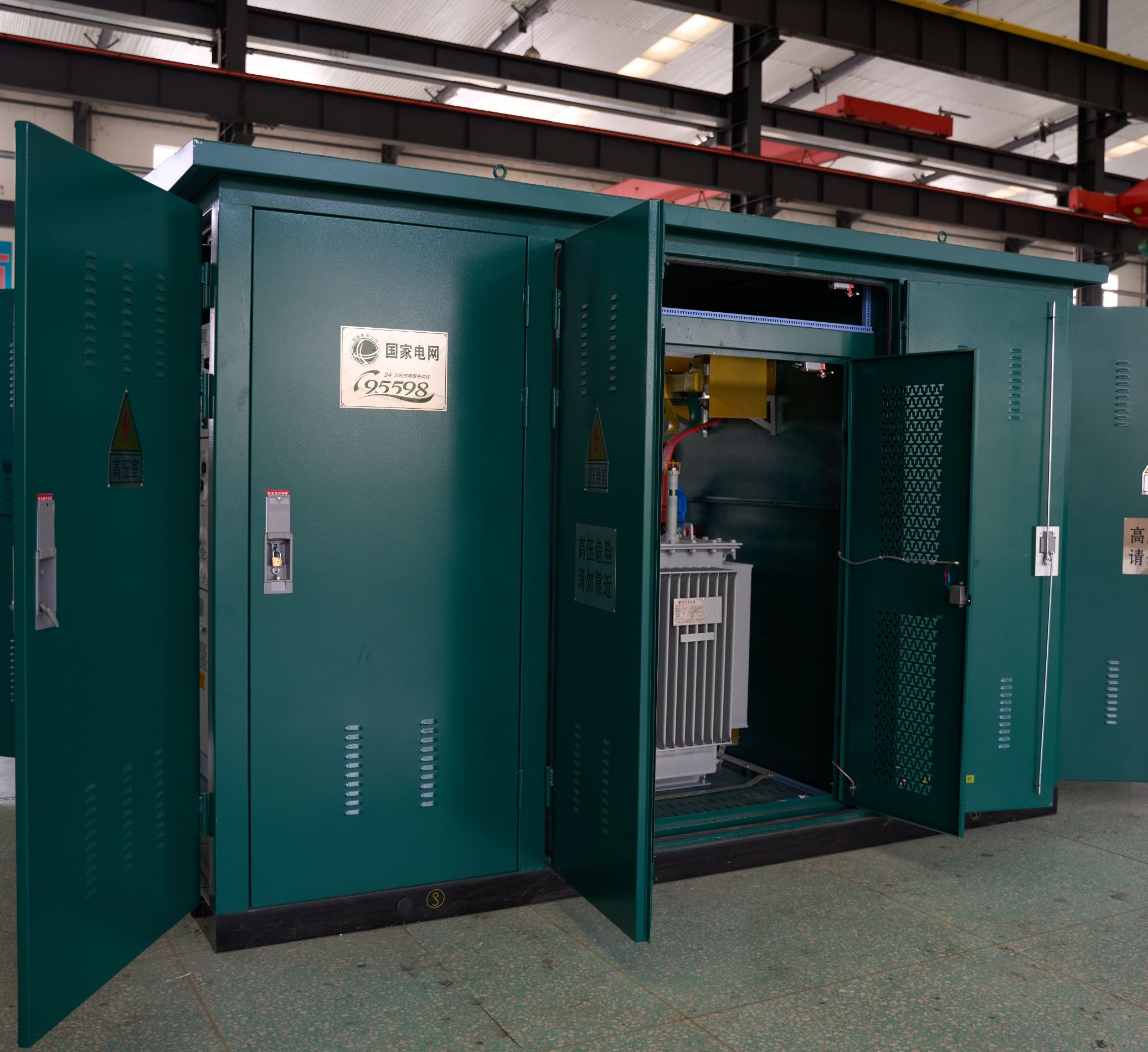
The Wind Turbine Step-Up Transformer 2000kVA 35kV is purpose-built for onshore wind farms, enabling efficient voltage conversion from wind turbine generators to medium-voltage collection networks. Designed to operate reliably under fluctuating wind loads and harsh outdoor conditions, this transformer ensures stable power transmission and reduced energy losses across wind power systems.
The oil-immersed insulation structure provides excellent thermal stability and long service life, while the optimized magnetic core minimizes no-load losses and acoustic noise. High-quality windings and reinforced insulation withstand frequent load variations caused by changing wind speeds.
- Primary Voltage Ratings 35kV, 34.5kV, 33kV, 46kV or others
- Secondary Voltage Ratings 800V, 600V, 380V, 34.5, 33,24, 12kV or customized
- H.V. Tap Range ± 2×2.5% HV taps or others
- Type Solar Step-up Transformer
- BIL 35kV
- Standards IEEE, ANSI, NEMA, IEC, GB
- Application medium-voltage collector networks, wind power transmission.
- Power Rating 2000kVA
- Certificate UL ,CESI
- Cooling Method ONAN, KNAN
- Oil Mineral Oil or FR3
- Opeartion Step-up
Technical Specifications
Customization Optional
Packing and Shipping
Manufacturer Test
Routine Testing
Application
Technical Specifications
2000kVA 35kV Wind Turbine Step-Up Transformer for Onshore Wind Farms
Technical Specifications
Accessories
| Rated Power | 2000kVA | |
| Rating Primary Voltage | 35kV | |
| Secondary Voltage | Customized | |
| Frequency | 50/60Hz | |
| Vector Group | Dyn11,Ynd11,Dyn11yn11,YNd11d11 | |
| Winding Material | Aluminum/Copper | |
| Zero-Sequence Impedance | Customized | |
| Altitude | ≤1,000m or Customized | |
| Color | ANSI 70 Light gray/Munsell 7GY3.29/1.5 or customized etc | |
| Tank material | Mild Steel, 304 Stainless Steel | |
| HV Bushing |
| LV Bushing |
| Tap changer |
| Oil level gauge |
| Oil temperature indicator |
| Pressure relief device |
| CT |
| Lifting hook for complete transformer |
| Name plate |
| Radiators |
| Oil upper filtering valve |
| Oil drain valve with 3/8" sampler |
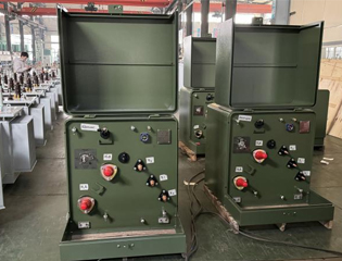
| Terminal box |
Customization Optional
2000kVA 35kV Wind Turbine Step-Up Transformer for Onshore Wind Farms
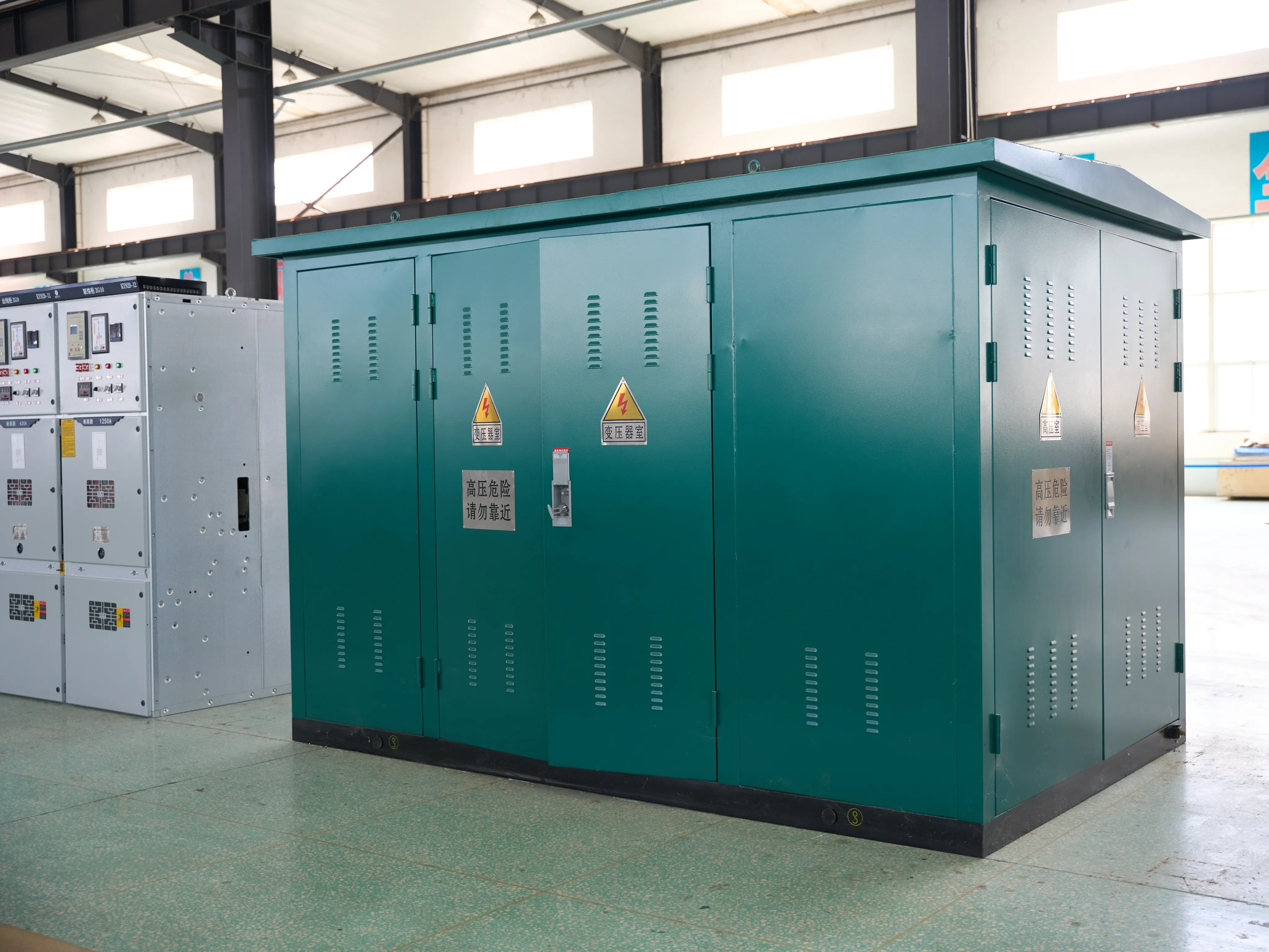
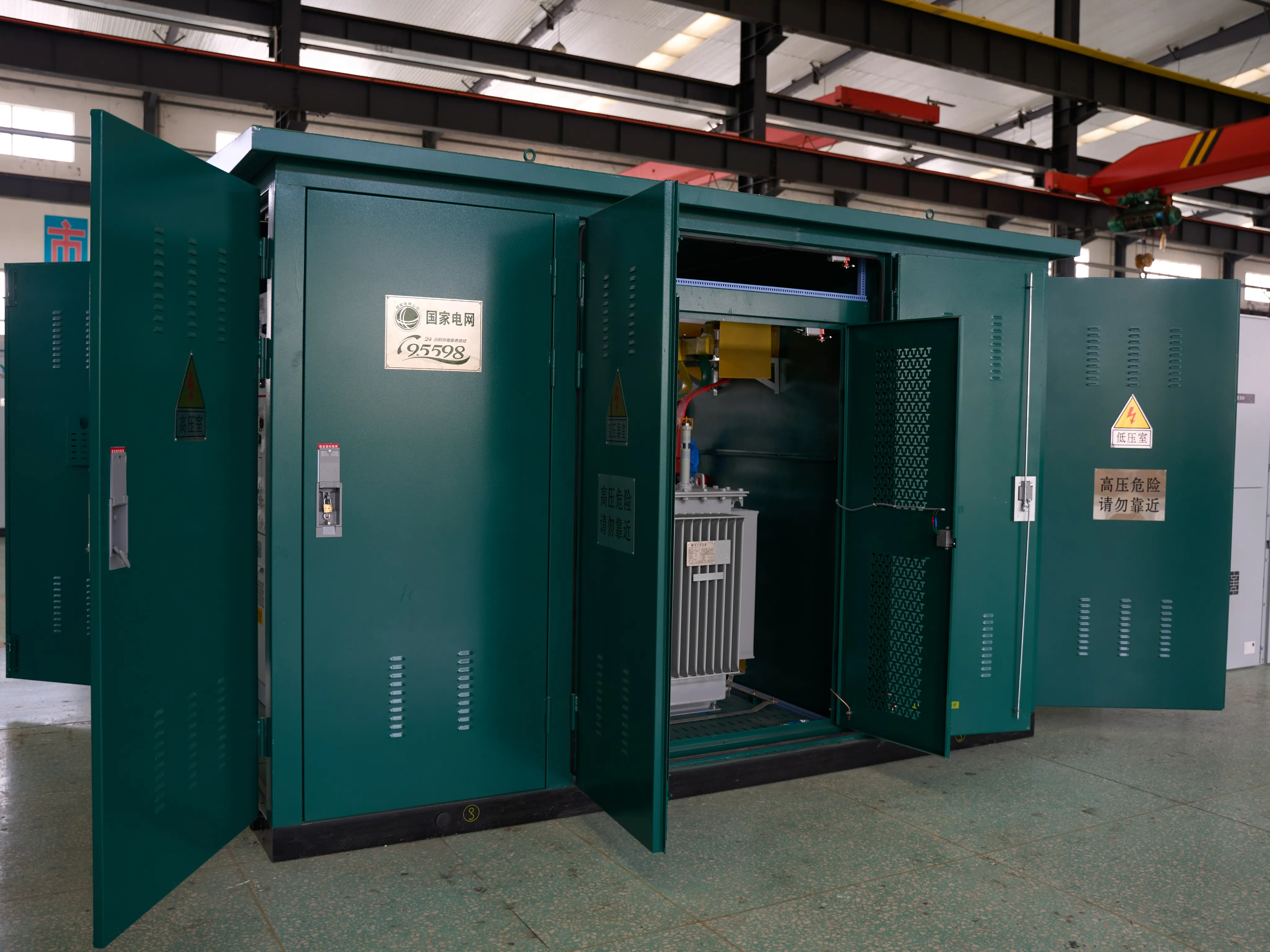
The 2000kVA 35kV Wind Turbine Step-Up Transformer offers flexible electrical customization to match diverse wind farm configurations. Primary voltage ratings can be tailored to different turbine generator outputs, while secondary voltages are adjustable to suit 35kV or alternative medium-voltage collector systems. Vector group selection is optimized for wind turbine converters, ensuring stable harmonic performance and smooth grid integration. Customers may choose copper or aluminum windings depending on efficiency targets, thermal requirements, and investment preferences. Tap changer options, including off-circuit or on-load tap changers, enable voltage regulation under variable wind generation conditions.
Mechanical and environmental customization enhances adaptability to challenging onshore sites. The transformer tank can be designed for outdoor installation with enhanced corrosion protection suitable for coastal, cold-climate, or high-humidity environments. Cooling methods such as ONAN or ONAF can be selected based on ambient temperature and loading profile. Noise reduction designs are available to meet environmental regulations near residential areas. Optional monitoring systems, including winding temperature indicators, oil level sensors, and remote condition monitoring interfaces, support predictive maintenance and reliable long-term operation.
Packing and Shipping
2000kVA 35kV Wind Turbine Step-Up Transformer for Onshore Wind Farms
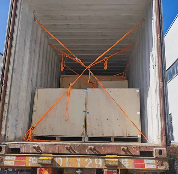
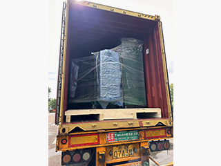
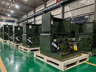
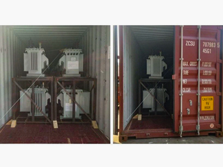
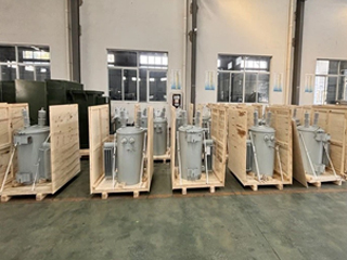
Packing and shipping of the Wind Turbine Step-Up Transformer are executed according to strict quality and logistics standards to ensure safe delivery to wind farm sites. Prior to packing, the transformer undergoes final inspection and surface treatment to confirm that all components are securely installed and free from damage. External accessories, terminals, and protection devices are reinforced with protective covers to prevent impact during transportation.
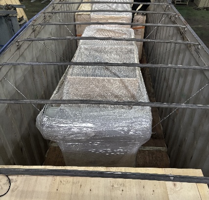
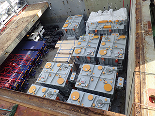
For long-distance or international transport, the transformer may be shipped oil-filled, nitrogen-filled, or vacuum-sealed depending on customer requirements and transport duration. Moisture-resistant wrapping and anti-corrosion treatments are applied to protect internal insulation and external surfaces. Sensitive components such as bushings and radiators may be detached and packed separately in custom crates to minimize transit risks.
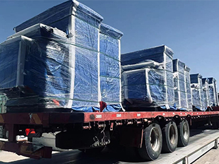
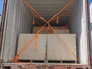
The transformer main body is mounted on heavy-duty steel or treated wooden skids engineered to distribute weight evenly and maintain stability during lifting. Shock-absorbing materials are used to reduce vibration during road, rail, or sea transport. All wooden packaging complies with ISPM 15 standards to meet international phytosanitary regulations.
Clear handling labels, lifting instructions, center-of-gravity markings, and safety notices are applied to each package. Comprehensive shipping documentation—including packing lists, test certificates, manuals, and compliance reports—is provided to ensure smooth customs clearance and on-site installation. This process ensures the transformer arrives ready for commissioning with minimal preparation.
For long-distance or international transport, the transformer may be shipped oil-filled, nitrogen-filled, or vacuum-sealed depending on customer requirements and transport duration. Moisture-resistant wrapping and anti-corrosion treatments are applied to protect internal insulation and external surfaces. Sensitive components such as bushings and radiators may be detached and packed separately in custom crates to minimize transit risks.
The transformer main body is mounted on heavy-duty steel or treated wooden skids engineered to distribute weight evenly and maintain stability during lifting. Shock-absorbing materials are used to reduce vibration during road, rail, or sea transport. All wooden packaging complies with ISPM 15 standards to meet international phytosanitary regulations.
Clear handling labels, lifting instructions, center-of-gravity markings, and safety notices are applied to each package. Comprehensive shipping documentation—including packing lists, test certificates, manuals, and compliance reports—is provided to ensure smooth customs clearance and on-site installation. This process ensures the transformer arrives ready for commissioning with minimal preparation.
32
32 years of industry experience
Manufacturer Test
2000kVA 35kV Wind Turbine Step-Up Transformer for Onshore Wind Farms
Progress Test
Progress testing is carried out throughout the manufacturing cycle to ensure consistent quality and compliance with design specifications. Incoming raw materials, including core steel, winding conductors, insulation materials, and transformer oil, are inspected and verified before production. Core assembly inspections confirm lamination alignment, stacking pressure, and magnetic performance.
During winding and insulation processes, dimensional accuracy, insulation spacing, and mechanical strength are monitored. Coil assemblies undergo controlled drying and vacuum treatment to remove moisture and enhance dielectric strength. Intermediate electrical checks, such as winding resistance and insulation resistance tests, verify electrical integrity before final assembly.
Tank fabrication, welding quality, and surface coating thickness are inspected, followed by pressure and leakage tests. Oil filtration and filling processes are monitored to ensure cleanliness. All results are documented, ensuring traceability and early detection of potential deviations.
Design Tests
All transformer will be test after finished the production, test items as follows:
♦ Insulation Power Factor
♦ Winding Resistance
♦ Impulse Tests
♦ On load Loss Test
♦ No Load Loss Test
♦ Leak Test
♦ DC Insulation Resistance Test
♦ Transformer Turns Ratio/TTR (All Tap Voltages)
♦ Impedance Voltage & Load Loss (Rated Voltage)
♦ Excitation & No-Load Loss (Rated Voltage)
♦ Applied Voltage
♦ Induced Voltage
♦ Lightning Impulse
♦ Insulation Resistance (Rated Voltage)
♦ Temperature Rise
Transformer Factory Acceptance Test
The Factory Acceptance Test confirms that the transformer meets contractual and technical requirements. Routine tests include winding resistance, voltage ratio, polarity, and vector group verification. No-load and load loss measurements validate efficiency and thermal design. Dielectric tests such as applied voltage and induced voltage withstand tests, ensure insulation reliability. Oil samples are analyzed for dielectric strength and moisture content. Functional tests of accessories and monitoring devices complete the FAT process, with results documented for approval.
During Factory Acceptance Testing, the 2000kVA 35kV Wind Turbine Step-Up Transformer is evaluated for efficiency, thermal performance, and operational stability under simulated wind load conditions. No-load and load loss measurements, temperature rise tests, and insulation oil dielectric strength assessments are performed to validate design performance. Successful completion of FAT confirms the transformer’s readiness for reliable operation in onshore wind farm grid-connection systems.
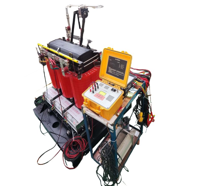
Routine Test - On load Loss Test
Purpose of Testing
The purpose of On-load Loss Test is to measure the active power loss of the transformer under rated voltage and rated load, evaluate its energy efficiency level and design compliance, and provide a basis for energy consumption calculation and performance optimization during operation.
Testing Equipment
Power transformer test system (e.g. OMICRON, ISA, Tettex, Vanguard, etc.)
Voltage source and current source (usually rated voltage, or adjusted according to the test standard, such as 10 KV, 20 KV, 35 KV, etc.)
Temperature and humidity meter (used to record ambient temperature and humidity for correction of test data)
Voltage source and current source (usually rated voltage, or adjusted according to the test standard, such as 10 KV, 20 KV, 35 KV, etc.)
Temperature and humidity meter (used to record ambient temperature and humidity for correction of test data)
Pre-Test Preparation
Disconnect the transformer high voltage, low voltage and neutral power supply to ensure that the equipment is properly grounded and safely discharged.
The test environment should be dry and rainless, with a relative humidity of less than 75% and a recommended temperature range of 20–30°C.
The test environment should be dry and rainless, with a relative humidity of less than 75% and a recommended temperature range of 20–30°C.
Test Progress
Connect the Test Instrument:
Connect the test equipment to the appropriate terminals of the device under test and ensure that all wiring is correct and the device is well grounded.
Apply Test Voltage:
Apply the specified test voltage at the rated frequency and adjust the low voltage side to maintain the rated current (or specified current).
Measure and Record
Start the test and record the following parameters:
On-Load Loss Power
Input Power and Output Power
Current
Voltage
Temperature (temperature rise or winding temperature)
Ambient temperature and humidity during the test
On-Load Loss Power
Input Power and Output Power
Current
Voltage
Temperature (temperature rise or winding temperature)
Ambient temperature and humidity during the test
Temperature Correction
The measured loss data is corrected based on a reference temperature (usually 20°C) to ensure the accuracy of the results.
Repeat Testing (if necessary)
Test different tap positions (Tap Changer) and record and compare the load loss data of each tap point.
Evaluation Criteria (Reference)
Evaluate the test results based on the equipment type and manufacturer requirements. If the load losses are low and the efficiency is high, it is considered "normal".
*These comprehensive tests ensure that each transformer meets performance standards and operates
reliably under various conditions.
Application
Widely used in utility-scale wind energy projects, the transformer supports efficient voltage conversion, grid integration, and long-term operation under variable wind and load conditions.


Technical Advantages
● 30+ years of manufacturing experience
● ISO and UL certified production
● Customized cable and transformer solutions


Product Packaging
Transformers Packaging (1)
Transformers Packaging (2)
Transformers Packaging (3)
Transformers Packaging (4)
Transformers Packaging (5)
Transformers Packaging (6)
Transformers Packaging (7)
Transformers Packaging (8)
Related Products
167kVA Conventional Type Single Phase Pole Mounted Transformer
NPC ELECTRIC'S 167kVA Single Phase pole Mounted transformer is a high capacity single phase distribution transformer designed for medium to high load distribution systems. It is mainly used in residential, commercial, agricultural and light industrial applications to provide stable single phase power to ensure reliable operation of user-side equipment. It complies with international standards such as ANSI/IEEE C57, IEC60076 and other standards to ensure its high quality and stability. Standard features include mineral oil insulation (ONAN cooling), aluminum or copper windings, primary voltages 2.4kV–34.5kV grounded wye or delta (common: 7200/12470GrdY, 7620/13200GrdY, 12470GrdY/7200, 24940GrdY/14400, 34500GrdY/19920), secondary 120/240V or 240/120V split-phase (options for 277V/480V or custom), BIL ratings 95–150kV HV / 30kV LV, impedance typically 1.5–4.5%, ±2×2.5% or 5-position tap changer, conventional or CSP (completely self-protected) configurations with internal fuses, lightning arresters, weak-link protection, pressure relief valve, oil sight gauge, and ANSI 70 gray tank finish. Efficiency typically reaches 99.33% at 50% load per DOE levels (with 2029 amendments targeting further reductions for units ≥100 kVA), with low sound levels and corrosion-resistant hardware for extended outdoor service.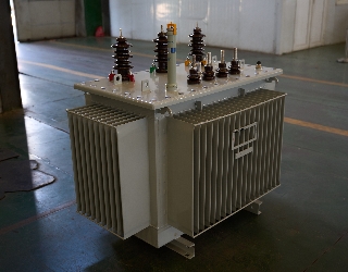
750kVA Oil Immersed Transformer
NPC ELECTRIC's 750kVA oil-immersed transformer uses advanced oil-immersed cooling technology to provide efficient and stable power conversion. The transformer complies with international standards such as the International Electrotechnical Commission (IEC) and ISO 9001, ensuring the high quality and safety of the product. Its sturdy structure and excellent overload resistance are widely used in industrial, commercial, and power network fields.
35kV Oil Immersed Transformer
NPC ELECTRIC's 35kV Oil Immersed Transformer is a premium three-phase power transformer optimized for high-voltage step-down in 50/60Hz AC systems with primary ratings of 35kV (or 33-38.5kV range). It incorporates a robust conservator or fully sealed tank design with efficient radiator cooling (ONAN standard, ONAF optional), ensuring exceptional thermal dissipation, moisture exclusion. Outdoor-rated with pollution-resistant bushings (BIL 170-200kV), Dyn11/Ynd1 vector groups, and low noise (<62dB), it provides stable 35kV to secondary voltages (e.g., 10kV/6.3kV/0.4kV) conversion, enhancing grid stability, minimizing transmission losses, and supporting demanding applications in harsh or high-altitude conditions.
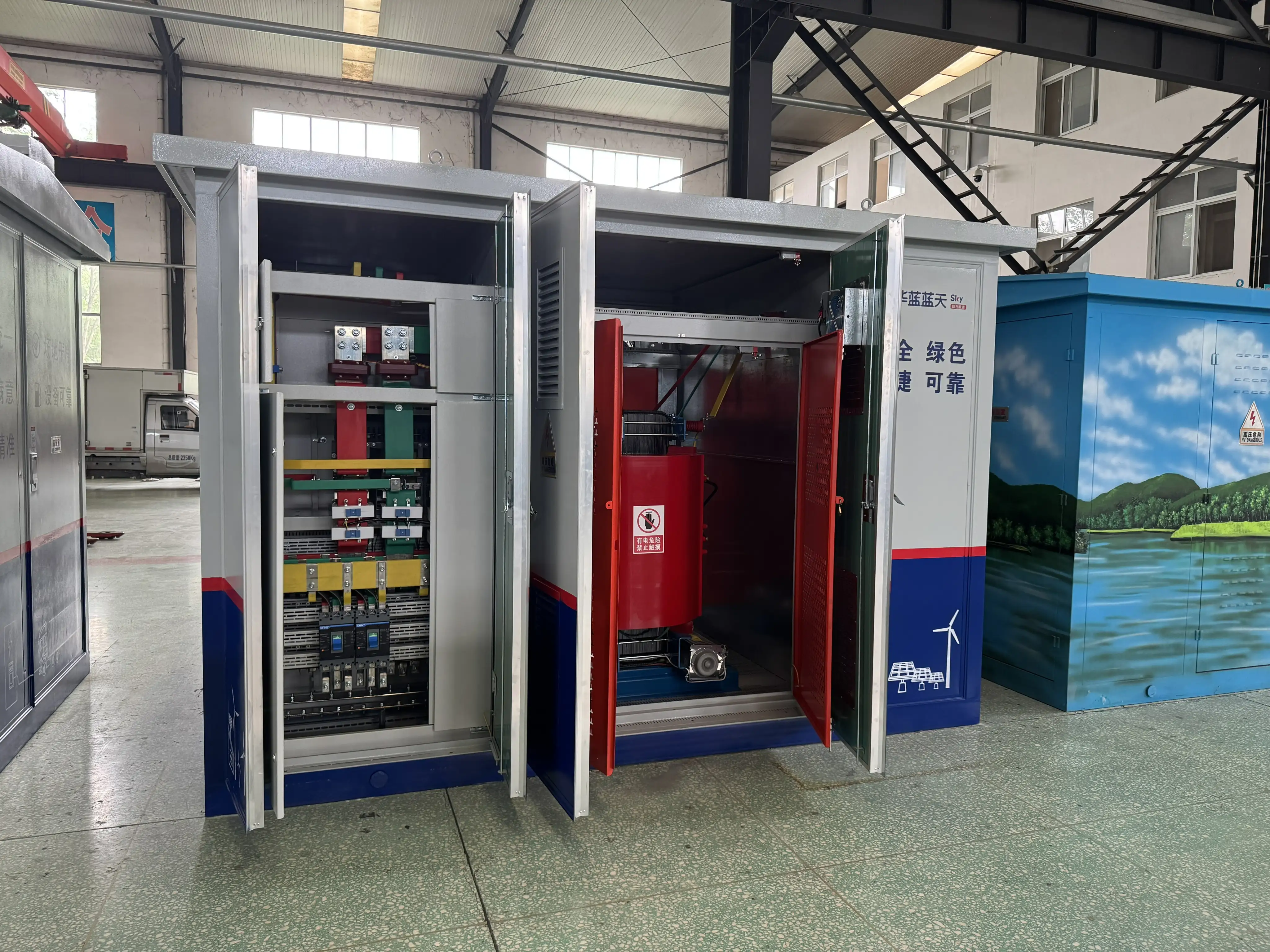
Step Up Dry Type Transformer Copper Winding High Overload Capacity
The Step Up Dry Type Transformer Copper Winding High Overload Capacity is a robust, oil-free power solution designed to increase (step up) voltage from lower primary levels to higher secondary outputs for efficient power transmission in indoor applications. This three-phase cast resin dry type transformer features premium high-conductivity copper windings fully encapsulated in epoxy resin under vacuum pressure, paired with low-loss grain-oriented silicon steel cores to achieve superior energy efficiency (typically 98%+), minimal no-load and load losses, and excellent partial discharge performance (<10pC). Compliant with IEC 60076-11, IEEE/ANSI, and relevant efficiency standards, this transformer commonly steps up voltages such as 0.4kV/480V primary to 6.6kV, 11kV, 13.8kV, 22kV, or 35kV secondary (Dyn11 or custom vector group), with capacities from 100kVA to several MVA, making it ideal for renewable energy systems, generator step-up, industrial processes, and utility indoor substations prioritizing safety, sustainability, and overload resilience.
1500kVA Radial Feed Pad Mounted transformer DOE 2016
The 1500kVA Radial Feed Pad-Mounted Transformer is designed for reliable medium-voltage power distribution in utility, commercial, and renewable energy (solar) applications. Engineered to comply with IEEE C57.12.34, C57.12.24, C57.12.00, and DOE 2016 efficiency standards, this pad-mounted transformer is ideal for step-down applications from 12.47kV to 480/277V. Standard features include mineral oil or FR3 natural ester fluid (ONAN cooling), aluminum or copper windings, primary voltage 13.8kV (13800V Delta or 12470GrdY/7200 common), secondary 480Y/277V (or 208Y/120V, custom options), BIL 95kV HV / 30kV LV, impedance 5.75–7.0% (±7.5%), ±2×2.5% taps, radial-feed dead-front design with three high-voltage bushings (H1, H2, H3), bayonet fuses + partial-range current-limiting fuses, load-break switch (optional), lightning arresters, pressure relief valve, oil level/temperature gauges, and ANSI 70 gray (or Munsell green) finish.
3150kVA Oil Immersed Transformer
3150kVA Oil Immersed Transformer is a high-capacity three-phase power transformer optimized for efficient voltage transformation in 50/60Hz AC medium-voltage networks, with primary ratings commonly at 11kV, 22kV, 33kV, or 35kV (adaptable to 10–38.5kV) and secondary at 0.4kV, 0.69kV, 6.3kV, 10kV, or 11kV. Employing advanced high-permeability grain-oriented silicon steel core (S13/S20 series compliant) for dramatically reduced no-load losses (typically 3200–5400W), high-purity copper windings, and premium insulating oil (IEC 60296 compliant, dielectric >60kV/2.5mm), it achieves low load losses (around 18–22kW at 75°C), strong overload capability (up to 150–180% short-duration), noise below 65dB, and efficiency exceeding 99%.This transformer minimizes operational expenses, transmission losses, and environmental impact in large-scale industrial, utility, and renewable setups.FAQ From Customers
-
What is a Transformer?A transformer is an electrical device used to change the voltage of alternating current (AC). It works on the principle of electromagnetic induction, converting high-voltage current into low-voltage current or low-voltage current into high-voltage current. Transformers are widely used in power transmission, distribution systems, and various electronic devices.
-
What are the main uses of a transformer?The main use of a transformer is voltage conversion. Transformers are used in power transmission systems to help transfer electricity from power plants to consumers. In addition, transformers are also used in electronic devices such as chargers, televisions, power adapters, etc., to adjust the voltage to meet the requirements of different devices.
-
Do you have UL listed?Yes, our transformer has UL listed. We have exported to America many pad mounted transformer,substation transformer and HV.
Welcome your inquiry
Honesty, Integrity, Frugality, Activeness and Passion