


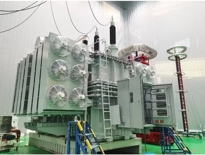
400kV Power Transformer: High-Voltage Substation Solutions
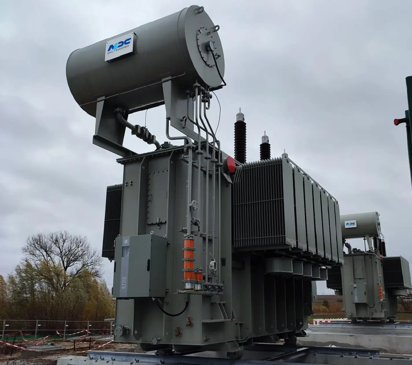
NPC Electric 400kV Power Transformer represents the pinnacle of Extra-High Voltage (EHV) engineering, specifically designed to handle the massive energy loads of modern national grids and renewable energy hubs. This unit utilizes a sophisticated cooling architecture and a low-flux density core design to ensure maximum efficiency and minimal noise pollution. Each transformer is built with a high-strength, vacuum-proof tank and premium-grade insulation materials that have undergone rigorous moisture extraction. With its advanced electromagnetic shielding, the 400kV model minimizes eddy current heating, ensuring a stable service life exceeding 30 years. It serves as a vital link in stepping down bulk power from 400kV transmission lines to regional distribution levels, offering unmatched short-circuit withstand capabilities and thermal stability for critical infrastructure projects worldwide.
- Primary Voltage Ratings 220kV 230kV 400 kV
- Secondary Voltage Ratings 69/35/37/34.5/26.4./11/10.5/6.6/13.2 kV or others
- H.V. Tap Range ± 8×1.25% HV taps or others
- Type Oil-immersed power transformer
- BIL 900kV
- Standards IEEE, ANSI, IEC, GB
- Application Renewable Energy Mega-Hubs, Industrial Zones, Data Centers
- Power Rating 500-250000kVA
- Certificate UL, ISO, CESI
- Cooling Method ONAN/ ONAF
- Opeartion Step Down & Step Up
Technical Specifications
Customization Optional
Packing and Shipping
Manufacturer Test
Routine Testing
Application
Technical Specifications
400kV Power Transformer: High-Voltage Substation Solutions
Technical Specifications
Accessories
| Rated Power | 500-250000kVA |
| Rating Primary Voltage | 220kV 230kV 400kV |
| Secondary Voltage |
69/35/37/34.5/26.4/11/10.5/6.6/13.2 kV Customized |
| Frequency | 50/60Hz |
| Vector Group | Dyn11, YD11, YNd11 or anothers |
| Winding Material | Aluminum/Copper |
| Efficiency | As IEEE, CAS Std or Customized |
| Impedance Voltage | As IEC |
| Altitude | ≤1,000m or Customized |
| Enclosure material | Mid Steel |
| HV Bushing |
| LV Bushing |
| OLTC/NLTC |
| Lifting hook for complete transformer |
| Name plate |
| Oil temperature |
| Winding temperature |
| Radiators |
| Oil level |
| Pressure relief valve |
| CT |
Customization Optional
400kV Power Transformer: High-Voltage Substation Solutions
To meet specific grid codes and environmental constraints, our 400kV transformers offer a comprehensive suite of structural and thermal customization. Clients can choose between Auto-transformer or Multi-winding configurations depending on the substation’s voltage ratio requirements. We provide diverse cooling arrangements, ranging from traditional ONAF (Oil Natural Air Forced) to advanced ODAN (Oil Directed Air Natural) systems for high-load density areas. Furthermore, the tank shape can be modified to "Bell-type" or "Conventional-type" to facilitate easier site assembly or transport through restricted tunnels. We also offer specialized low-noise fan blades and acoustic enclosures for substations located near residential or noise-sensitive urban zones.
In addition to physical hardware, we provide integrated digital intelligence tailored to utility requirements. This includes the installation of smart monitoring systems for real-time tracking of partial discharge, bushing health, and dissolved gas analysis (DGA). For harsh environments, we offer customization of the external protection, such as high-creepage composite bushings for desert or saline coastal conditions and specialized C5-M grade anti-corrosion coatings. The control interface can be fully customized to support various communication protocols, including IEC 61850, allowing for seamless remote operation and predictive maintenance scheduling within a Smart Grid framework.
Packing and Shipping
400kV Power Transformer: High-Voltage Substation Solutions
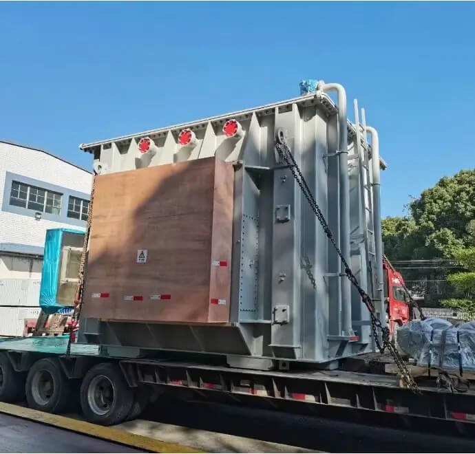
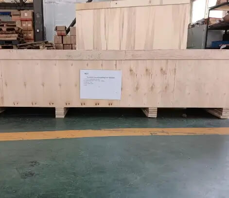
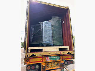
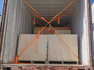
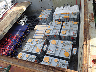
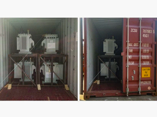
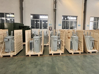
Shipping a 400kV transformer is a precision-engineered logistical operation that begins long before the unit leaves the factory. Due to the extreme dimensions and weight of the main tank, the transformer is shipped partially disassembled. The main body is emptied of insulation oil to reduce weight and is instead filled with dry nitrogen or dry air under constant positive pressure. This prevents any atmospheric moisture from contaminating the high-grade insulation system during transit. All vital accessories—such as the 400kV porcelain or composite bushings, radiator banks, and the oil conservator—are securely packed in custom-engineered, seaworthy steel-framed wooden crates.
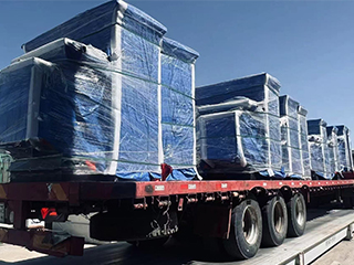
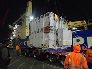
The inland transportation phase utilizes heavy-duty hydraulic modular trailers (Goldhofer or similar) to navigate the journey from the factory to the port. Our logistics team performs a comprehensive route survey to account for bridge load-bearing capacities and overhead clearances. The transformer is secured to the trailer or vessel deck using high-tensile lashing chains and anti-slip mats. For international sea freight, we prioritize "Heavy Lift" vessels or Ro-Ro (Roll-on/Roll-off) ships. To protect against the corrosive effects of salt air, all machined surfaces and electrical terminals are coated with a specialized peelable plastic or Tectyl anti-rust compound.
During the entire voyage, the transformer is monitored by multiple three-axis electronic impact recorders. These devices provide a continuous log of longitudinal, lateral, and vertical accelerations, ensuring that the internal core-and-coil assembly has not been subjected to forces beyond the design limit. GPS tracking units provide real-time location data to the project management team. Upon arrival at the destination port, a specialized heavy-lift crew manages the transfer, ensuring the unit is handled with extreme care to maintain the mechanical integrity established during factory assembly.
The final "last-mile" delivery to the substation pad often requires specialized "jacking and rolling" equipment if the site does not allow for large crane access. Once the transformer is positioned on its foundation, the nitrogen is purged, and the unit is refilled with hot, degassed insulation oil under a high vacuum. This meticulous process ensures that no air pockets remain in the windings. Our end-to-end shipping protocol guarantees that the 400kV transformer arrives on-site in factory-perfect condition, ready for final assembly and the high-voltage testing phase prior to energization.
32
32 years of industry experience
Manufacturer Test
400kV Power Transformer: High-Voltage Substation Solutions
Progress test
Following the Vapor Phase Drying (VPD) process, we conduct an Insulation Resistance (IR) and Polarization Index (PI) Test to confirm the cellulose materials are bone-dry. A Vacuum Drop Test is performed on the tank to ensure its hermetic integrity before oil filling. Finally, a Pre-seal Dielectric Test of the insulation oil is carried out to verify that the breakdown voltage (BDV) meets the strict 70kV+ threshold required for 400kV EHV equipment. During manufacturing, the 400kV Power Transformer is subjected to strict progress tests at each critical production stage. Core stacking inspections verify magnetic circuit precision and structural stability, while high-voltage winding processes are closely monitored to ensure insulation uniformity and dimensional accuracy. Intermediate electrical tests, including insulation resistance measurement and turns ratio verification, confirm that the 400kV power transformer meets all design and safety requirements before final assembly.
Design Tests
All transformers will be tested after finishing the production test items as below:
♦ Leak testing with pressure for liquid-immersed transformers
♦ Test of transformer oil
♦ Measurement of voltage ratio and check of phase displacement
♦ Measurement of winding DC resistance
♦ Capacitive bushing test
♦ Measurement of dissipation factor (tan δ) of the insulation system capacitances, and determination of capacitances windings-to-earth
♦ Measurement of no-load loss and current at 90%,100%,110% of rated voltage
♦ Operation test on on-load tap-changer
♦ Measurement of short-circuit impedance and load loss
♦ Lightning impulse test
♦ Induced-voltage test with partial discharge measurement
♦ Auxiliary wiring check
♦ Current transformer test
♦ Frequency response analysis test
Transformer Factory Acceptance Test
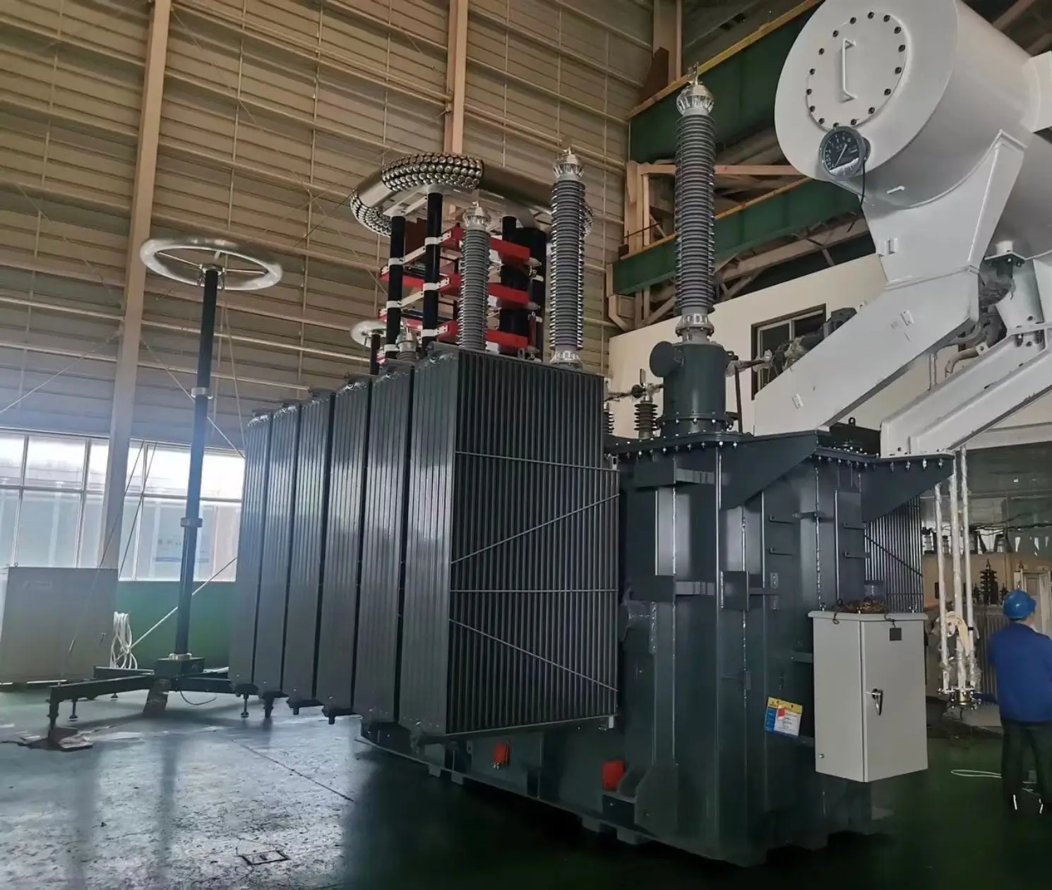
This test sequence focuses on efficiency and structural stability. We perform No-load and Load Loss Measurements to verify compliance with guaranteed efficiency values. Sweep Frequency Response Analysis (SFRA) is used to create a baseline for internal winding geometry. Furthermore, we conduct a Temperature Rise Test under full-load conditions to ensure the cooling system maintains oil and winding temperatures within design limits. Finally, a Zero-sequence Impedance Test is performed for fault calculation accuracy. During Factory Acceptance Testing, the 400kV Power Transformer is evaluated for efficiency, thermal performance, and operational stability. No-load and load loss measurements, temperature rise tests, and insulation oil dielectric strength assessments are conducted to validate design performance. Successful completion of FAT confirms that the 400kV power transformer is fully qualified for continuous operation in high-voltage substation and transmission applications.
Routine Test - Induced Voltage
Purpose of Testing
The purpose of the Induced Voltage test is to simulate the electrical stress that the equipment may encounter under actual working conditions by applying an induced voltage, thereby evaluating the tolerance and stability of the equipment's insulation system. This test helps to detect the insulation performance of the equipment under high voltage conditions and ensure its safety and reliability in operation.
Testing Equipment
Induced Voltage Tester (e.g. OMICRON, Megger, HioKI, etc.)
AC voltage source, commonly 2 kV, 5 kV, 10 kV, or customized according to test requirements.
Environmental thermometer and hygrometer, used to record the temperature and humidity of the environment for appropriate test evaluation.
AC voltage source, commonly 2 kV, 5 kV, 10 kV, or customized according to test requirements.
Environmental thermometer and hygrometer, used to record the temperature and humidity of the environment for appropriate test evaluation.
Pre-Test Preparation
Disconnect all relevant power supplies and ensure that the equipment is properly grounded and discharged.
Check the connection wires and terminals to ensure they are secure and free of contamination.
Test under suitable environmental conditions: relative humidity below 75%, no rain (recommended temperature: 20-30°C).
Check the connection wires and terminals to ensure they are secure and free of contamination.
Test under suitable environmental conditions: relative humidity below 75%, no rain (recommended temperature: 20-30°C).
Test Progress
Connect the Test Instrument:
Connect the test equipment to the appropriate terminals or bushings of the device under test, ensuring that the connections are secure and properly grounded.
Apply Test Voltage:
Select the appropriate induction voltage according to the rated voltage and standard of the equipment.
Connect the test equipment to the appropriate terminals or bushings of the device under test, ensuring that the connections are secure and properly grounded.
Apply Test Voltage:
Select the appropriate induction voltage according to the rated voltage and standard of the equipment.
Test Standard
IEC 60076 Oil-immersed power transformers
Measure and Record
Start the test and record the following parameters:
Induced Voltage
Applied Current
Voltage peak, stability and waveform (waveform analysis)
Any abnormal current or voltage changes during the measurement process.
Induced Voltage
Applied Current
Voltage peak, stability and waveform (waveform analysis)
Any abnormal current or voltage changes during the measurement process.
Temperature Correction
The measured induced voltage data is corrected to the reference temperature (usually 20°C) to ensure the accuracy of the test results.
Repeat Testing (if necessary)
If necessary, test different windings (HV, MV, LV) and bushings separately and compare the results at different test points.
Evaluation Criteria (Reference)
Inductive voltage ≤ 1% (Excellent): normally and meets safety standards.
1% < Inductive voltage ≤ 3% (Good): still within acceptable range.
Inductive voltage > 3% : faulty or not meet safety requirements and requires further analysis and repair.
1% < Inductive voltage ≤ 3% (Good): still within acceptable range.
Inductive voltage > 3% : faulty or not meet safety requirements and requires further analysis and repair.
*These comprehensive tests ensure that each transformer meets performance standards and operates
reliably under various conditions.
Application
Installed at the step-up substation of a nuclear or large-scale thermal power plant, it efficiently converts generated voltage to 400kV for low-loss injection into the EHV transmission network, supporting bulk energy transport to industrial centers.


Technical Advantages
● 30+ years of manufacturing experience
● ISO and UL certified production
● Customized cable and transformer solutions


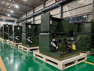
Product Packaging
Transformers Packaging (1)
Transformers Packaging (2)
Transformers Packaging (3)
Transformers Packaging (4)
Transformers Packaging (5)
Transformers Packaging (6)
Transformers Packaging (7)
Transformers Packaging (8)
Related Products
250kVA Dry Type Cast Resin Transformer 10kV/0.4kV Copper Core | CE/IEC/UL
Introducing the premium 250kVA Dry Type Cast Resin Transformer 10kV/0.4kV Copper Core, a high-performance, maintenance-free solution engineered for safe and efficient indoor power distribution. Featuring fully vacuum-cast epoxy resin windings with premium copper conductors, this three-phase transformer delivers exceptional low-loss performance, reduced no-load and load losses, and outstanding energy efficiency often surpassing 98%. The cast resin encapsulation provides superior moisture resistance, fire self-extinguishing properties, and high partial discharge immunity, eliminating risks associated with oil-filled units. With natural air (AN) cooling, low noise levels, Class F/H insulation, and robust short-circuit withstand capability, it ensures reliable operation in demanding environments. Certified to CE, IEC 60076-11, and UL equivalents where applicable, this compact dry-type transformer supports primary 10kV (with ±2×2.5% off-circuit taps) to secondary 0.4kV transformation, ideal for modern sustainable electrical infrastructures prioritizing safety, energy savings, and environmental compliance.
11/0.4kV Dry Type Transformer | Indoor Power Transformer
Discover the reliable 11/0.4kV Dry Type Transformer | Indoor Power Transformer, a safe, oil-free solution designed for efficient medium-to-low voltage conversion in indoor electrical installations. This three-phase dry-type transformer (typically cast resin or vacuum pressure impregnated) features premium low-loss silicon steel cores and high-conductivity copper windings, achieving superior energy efficiency often exceeding 98% and complying with IEC 60076-11 standards. The epoxy resin encapsulation provides excellent moisture resistance, fire self-extinguishing properties (F1 class), minimal partial discharge (<10pC), and robust short-circuit withstand capability. With natural air (AN) cooling and optional forced air (AF) upgrades, it offers low noise operation, Class F/H insulation, and maintenance-free performance in demanding environments. Ideal for step-down from 11kV primary (with ±2×2.5% or wider off-circuit taps) to 0.4kV secondary (Dyn11 vector group standard), this indoor power transformer supports capacities from 100kVA to several MVA, delivering stable, eco-friendly power distribution without oil-related risks.
1250kVA Dry Type Transformer
NPC ELECTRIC 1250kVA Dry-Type Transformer delivers reliable, oil-free power distribution with a compact and efficient design. Featuring advanced insulation and cooling systems, it ensures safe, low-maintenance operation, making it ideal for industrial and commercial applications. It provides environmentally friendly, cost-effective performance with a 1250kVA capacity. Compliant with DOE amended energy conservation standards (finalized April 2024, mandatory compliance from April 23, 2029, with a 20% reduction in losses for three-phase low-voltage dry-type units), ANSI/IEEE C57.12.01, NEMA ST-20, UL 1561, and CSA requirements, this low-voltage (≤600V) transformer provides outstanding efficiency, minimized thermal losses, significant energy savings, and enhanced fire safety without insulating fluids.
25kVA Conventional Type Single Phase Pole Mounted Transformer
NPC ELECTRIC'S 25kVA Conventional Type Single Phase pole Mounted transformer are designed for servicing residential overhead distribution loads. They are also suitable for light commercial loads, industrial lighting and diversified power applications. These transformers are designed for the application conditions normally encountered on electric utility power distribution systems. Types CSP, CP, SP and S are all available. ISO 9001: 2008 Certified. Typical specifications include mineral oil insulation (ONAN cooling), aluminum or copper windings, primary voltages 2.4 kV–34.5 kV grounded wye or delta (most common: 7200/12470GrdY, 7620/13200GrdY, 12470GrdY/7200, 24940GrdY/14400, 34500GrdY/19920), secondary 120/240 V or 240/120 V split-phase, BIL ratings 95–150 kV HV / 30 kV LV, impedance typically 2.0–4.0%, ±2×2.5% or 5-position tap changer, conventional or completely self-protected (CSP) versions with internal primary fuses, external weak-link cutout, lightning arresters, pressure relief device, oil sight gauge, and standard ANSI 70 gray tank finish. Efficiency usually reaches 98.90%–99.10%+, with low sound level and corrosion-resistant design for long outdoor service life.
200kVA Single Phase Pole Mounted Transformer
NPC ELECTRIC'S 200kVA single phase pole mounted transformer delivers exceptional reliability for demanding overhead power systems. It efficiently converts primary voltages like 11kV or 22kV to secondary levels such as 220V or 400V, supporting heavier loads in diverse environments. Constructed with low-loss grain-oriented steel cores and high-grade aluminum conductors, it achieves superior energy efficiency and reduced operational costs. Meeting ANSI/IEEE C57 standards, the weatherproof enclosure ensures protection against elements, with a 55°C temperature rise and ONAF cooling for enhanced performance. Essential safety integrations include overload fuses and oil level gauges, making it suitable for utilities aiming for minimal downtime. This transformer excels in providing stable power with low harmonic distortion, ideal for modern grid upgrades.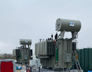
132kV 138kV Power Transformer
132kV 138kV power transformer complies with international standards as below standard: 1. IEC 60076 Power Transformers; 2. AS NZS 60076 Power Transformers CSAC88-16 Power Transformers; 3. ANSI/IEEE C57.12.00 IEEE Standard for General Requirements for Liquid-Immersed Distribution, Power, and Regulating Transformers; 4. GOST R 52719 Power Transformers - General Specifications; 5. EN60076 Poer Transformer; 6. Local After-Sales Services In North America South. Engineered for overloads (150% short-term), harmonic tolerance, low noise (<70dB), and robust corrosion protection for long-term outdoor operation.FAQ From Customers
-
What is a Transformer?A transformer is an electrical device used to change the voltage of alternating current (AC). It works on the principle of electromagnetic induction, converting high-voltage current into low-voltage current or low-voltage current into high-voltage current. Transformers are widely used in power transmission, distribution systems, and various electronic devices.
-
What are the main uses of a transformer?The main use of a transformer is voltage conversion. Transformers are used in power transmission systems to help transfer electricity from power plants to consumers. In addition, transformers are also used in electronic devices such as chargers, televisions, power adapters, etc., to adjust the voltage to meet the requirements of different devices.
-
Do you have UL listed?Yes, our transformer has UL listed. We have exported to America many pad mounted transformer,substation transformer and HV.
Welcome your inquiry
Honesty, Integrity, Frugality, Activeness and Passion